EP3292887B1 - Expulsion d'un agent d'extinction depuis un récipient - Google Patents
Expulsion d'un agent d'extinction depuis un récipient Download PDFInfo
- Publication number
- EP3292887B1 EP3292887B1 EP17184714.8A EP17184714A EP3292887B1 EP 3292887 B1 EP3292887 B1 EP 3292887B1 EP 17184714 A EP17184714 A EP 17184714A EP 3292887 B1 EP3292887 B1 EP 3292887B1
- Authority
- EP
- European Patent Office
- Prior art keywords
- container
- pressure
- propellant gas
- fire
- fire suppressant
- Prior art date
- Legal status (The legal status is an assumption and is not a legal conclusion. Google has not performed a legal analysis and makes no representation as to the accuracy of the status listed.)
- Active
Links
Images




Classifications
-
- A—HUMAN NECESSITIES
- A62—LIFE-SAVING; FIRE-FIGHTING
- A62C—FIRE-FIGHTING
- A62C35/00—Permanently-installed equipment
- A62C35/02—Permanently-installed equipment with containers for delivering the extinguishing substance
- A62C35/023—Permanently-installed equipment with containers for delivering the extinguishing substance the extinguishing material being expelled by compressed gas, taken from storage tanks, or by generating a pressure gas
-
- A—HUMAN NECESSITIES
- A62—LIFE-SAVING; FIRE-FIGHTING
- A62C—FIRE-FIGHTING
- A62C31/00—Delivery of fire-extinguishing material
-
- A—HUMAN NECESSITIES
- A62—LIFE-SAVING; FIRE-FIGHTING
- A62C—FIRE-FIGHTING
- A62C13/00—Portable extinguishers which are permanently pressurised or pressurised immediately before use
- A62C13/003—Extinguishers with spraying and projection of extinguishing agents by pressurised gas
-
- A—HUMAN NECESSITIES
- A62—LIFE-SAVING; FIRE-FIGHTING
- A62C—FIRE-FIGHTING
- A62C3/00—Fire prevention, containment or extinguishing specially adapted for particular objects or places
- A62C3/07—Fire prevention, containment or extinguishing specially adapted for particular objects or places in vehicles, e.g. in road vehicles
-
- A—HUMAN NECESSITIES
- A62—LIFE-SAVING; FIRE-FIGHTING
- A62C—FIRE-FIGHTING
- A62C31/00—Delivery of fire-extinguishing material
- A62C31/28—Accessories for delivery devices, e.g. supports
-
- A—HUMAN NECESSITIES
- A62—LIFE-SAVING; FIRE-FIGHTING
- A62C—FIRE-FIGHTING
- A62C35/00—Permanently-installed equipment
- A62C35/02—Permanently-installed equipment with containers for delivering the extinguishing substance
- A62C35/11—Permanently-installed equipment with containers for delivering the extinguishing substance controlled by a signal from the danger zone
- A62C35/13—Permanently-installed equipment with containers for delivering the extinguishing substance controlled by a signal from the danger zone with a finite supply of extinguishing material
-
- A—HUMAN NECESSITIES
- A62—LIFE-SAVING; FIRE-FIGHTING
- A62C—FIRE-FIGHTING
- A62C37/00—Control of fire-fighting equipment
- A62C37/04—Control of fire-fighting equipment with electrically-controlled release
-
- A—HUMAN NECESSITIES
- A62—LIFE-SAVING; FIRE-FIGHTING
- A62C—FIRE-FIGHTING
- A62C37/00—Control of fire-fighting equipment
- A62C37/36—Control of fire-fighting equipment an actuating signal being generated by a sensor separate from an outlet device
-
- F—MECHANICAL ENGINEERING; LIGHTING; HEATING; WEAPONS; BLASTING
- F16—ENGINEERING ELEMENTS AND UNITS; GENERAL MEASURES FOR PRODUCING AND MAINTAINING EFFECTIVE FUNCTIONING OF MACHINES OR INSTALLATIONS; THERMAL INSULATION IN GENERAL
- F16K—VALVES; TAPS; COCKS; ACTUATING-FLOATS; DEVICES FOR VENTING OR AERATING
- F16K17/00—Safety valves; Equalising valves, e.g. pressure relief valves
- F16K17/40—Safety valves; Equalising valves, e.g. pressure relief valves with a fracturing member, e.g. fracturing diaphragm, glass, fusible joint
- F16K17/403—Safety valves; Equalising valves, e.g. pressure relief valves with a fracturing member, e.g. fracturing diaphragm, glass, fusible joint with a fracturing valve member
Definitions
- the present disclosure generally relates to methods and systems for expelling a fire suppressant from a container, and more particularly to methods and systems for expelling a fire suppressant from a container by flowing a propellant gas into the container.
- WO 2013/028053 in accordance with its abstract, states a fire extinguishing system that comprises a hermetically sealed storage canister fabricated with at least one gas outlet and defining a hollow within; a powder form fire extinguishing agent stored inside the canister; a solid propellant, which is ignitable to generate gases; connected to the canister; and a rupturable seal disposed at the gas outlet, wherein the solid propellant generates gasses to aerate the fire extinguishing agent inside the canister and build a positive gas pressure until the gas pressure is sufficient to rupture the seal for discharging the fire extinguishing agent under pressurized gas flow.
- the fire suppression system has advantages when compared to conventional fire suppression systems. Whereas a conventional fire suppression system typically stores the energy to be used for expelling the fire suppressant within the container itself, the fire suppression system disclosed herein may store most of this energy outside of the container within one or more solid precursors of the propellant gas. Storing the energy in a solid form within the gas generator instead of as vapor pressure within the container allows for the container to have a reduced volume and a reduced wall thickness. Also, since the vapor pressure of the fire suppressant or another propellant gas that is pre-filled into the container is no longer the primary energy source for expelling the fire suppressant, fire suppressants having lower vapor pressures may be used.
- the distribution manifold 114 is coupled to the container 102 via the port 108 and the rupture disc 116.
- the distribution manifold 114 may include a network of pipes configured to distribute the expelled fire suppressant 104 to various areas of interest.
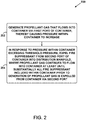
- the method 200 includes, in response to the pressure within the container exceeding a threshold pressure, expelling the fire suppressant from a second port of the container into the distribution manifold.
- the generated propellant gas continues to flow into the container via the first port at least until substantially all of the fire suppressant included within the container prior to the generation of the propellant gas is expelled from the container via the second port.
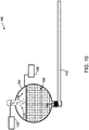
- the propellant gas 112 continues to flow into the container 102 and the pressure within the container 102 increases to exceed a predetermined threshold pressure.
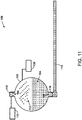
- the rupture disc 116 ruptures and the pressure within the container 102 begins to expel the fire suppressant 104 from the container 102 via the port 108 into the distribution manifold 114, as shown in Figure 11 .
- the threshold pressure may be a pressure within a range of 62,05 bar (900 pounds per square inch gauge (psig)) and 75,84 bar (1100 psig). More specifically, the threshold pressure may be substantially equal to 68,95 bar (1000 psig). That is, the method 200 may further involve expelling the fire suppressant 104 in response to the pressure within the container 102 exceeding a pressure within a range of 62,05 bar (900 psig) and 75,84 bar (1100 psig), or more specifically, the method 200 may further involve expelling the fire suppressant 104 in response to the pressure within the container 102 exceeding a pressure that is substantially equal to 68,95 bar (1000 psig).
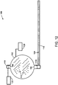
- the propellant gas 112 continues to flow into the container 102 via the port 106 at least until substantially all of the fire suppressant 104 is expelled from the container 102 via the port 108.
- Figure 12 shows that the propellant gas 112 continues to flow into the container 102 after the fire suppressant 104 has been fully or nearly expelled from the container 102.
- Figure 3 is a block diagram of the method 300.
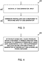
- the method 300 includes receiving, at the gas generator, an input.
- the gas generator 110 may receive the input from the control unit 122, for example.
- the control unit 122 may include a heat detector 122, a smoke detector 122, or a user interface 122, but other examples are possible.
- the method 300 includes generating the propellant gas in response to receiving the input at the gas generator.
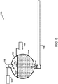
- Figure 8 shows the gas generator 110 beginning to generate the propellant gas 112 in response to the gas generator 110 receiving an input from the control unit 122.
- the gas generator 110 may mix one or more solid precursors of the propellant gas 112 in response to receiving the input.
- Figure 4 is a block diagram of the method 400.
- the method 400 includes, after rupturing the disc, causing the pressure within the container to remain greater than or equal to the threshold pressure at least until substantially all of the fire suppressant included within the container prior to the generation of the propellant gas is expelled from the container.
- the gas generator 110 continues to produce the propellant gas 112 and flow the propellant gas 112 into the container 102 at least until the fire suppressant 104 has been substantially expelled from the container 102.
- the ruptured disc 116 may perform a regulation function whereby the propellant gas 112 flows into the container 102 at a rate sufficient to maintain the pressure within the container 102 at or above the threshold pressure at least until the fire suppressant 104 has been substantially expelled from the container 102.
- Figure 5 is a block diagram of the method 500.
- the method 500 includes monitoring, via a pressure gauge, the pressure within the container generated at least in part by the second propellant gas.
- a second propellant gas is included within the container prior to the generation of the propellant gas.
- the propellant gas 118 may be filled into the container 102 along with the fire suppressant 104 prior to sealing the container 102.
- the pressure gauge 120 may monitor the pressure within the container 102 prior to, during, and/or after expulsion of the fire suppressant 104.
- the vapor pressure maintained within the container 102 may correspond, at least in part, to the propellant gas 118.
- Figure 6 is block diagram of the method 600.
- the method 600 includes flowing the expelled fire suppressant through the distribution manifold in a liquid phase.
- the method 600 includes dispensing the expelled fire suppressant from the distribution manifold in the liquid phase.
- the continuing generation of the propellant gas 112 maintains a pressure within the container 102 and the distribution manifold 114 sufficient to keep the fire suppressant 104 from evaporating at least until the fire suppressant 104 reaches dispensing nozzles of the distribution manifold 114.
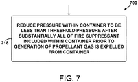
- Figure 7 is a block diagram of the method 700.
- the method 700 includes reducing the pressure within the container to be less than the threshold pressure after substantially all of the fire suppressant included within the container prior to the generation of the propellant gas is expelled from the container. This is discussed in more detail below with reference to Figure 13 .
- Figure 13 graphically depicts the pressure within the container 102 with respect to time.
- the pressure remains somewhat constant at low pressure, as the gas generator 110 has not yet been activated.
- the pressure within the container 102 may primarily correspond to the pre-filled propellant gas 118.
- the gas generator 110 is activated and begins generating the propellant gas 112, and the pressure within the container 102 begins to increase.
- the propellant gas 112 fills into the container 102 and the pressure increases.
- the rupture disc 116 ruptures in response to the pressure within the container 102 exceeding a predetermined threshold pressure.
- the ruptured rupture disc 116 allows the pressure built up in the container 102 to begin to expel some of the fire suppressant 104 out of the port 108.
- the propellant gas 112 continues to fill the container 102 while the fire suppressant 104 continues to be expelled from the container 102.
- the pressure remains somewhat constant at a high pressure during this time (e.g., near the predetermined threshold pressure).
- the gas generator 110 is no longer generating the propellant gas 112, and the pressure begins to decrease as the remainder of the propellant gases and the fire suppressant 104 continue to exit the container 102.
Landscapes
- Health & Medical Sciences (AREA)
- Public Health (AREA)
- Business, Economics & Management (AREA)
- Emergency Management (AREA)
- Engineering & Computer Science (AREA)
- General Engineering & Computer Science (AREA)
- Mechanical Engineering (AREA)
- Fire-Extinguishing By Fire Departments, And Fire-Extinguishing Equipment And Control Thereof (AREA)
Claims (12)
- Procédé (200) pour expulser un produit d'extinction d'incendie (104) en phase liquide depuis un contenant (102) jusque dans un collecteur de distribution (114), le procédé (200) comprenant les faits de :générer (202) un gaz propulseur (112) qui s'écoule dans le contenant (102) par l'intermédiaire d'un premier orifice (106) du contenant (102), ainsi faisant en sorte qu'une pression à l'intérieur du contenant (102) augmente, dans lequel le contenant (102) inclut le produit d'extinction d'incendie (104) en phase liquide avant la génération du gaz propulseur (112) ; eten réponse au fait que la pression à l'intérieur du contenant (102) dépasse une pression de seuil (204), expulser le produit d'extinction d'incendie (104) depuis un second orifice (108) du contenant (102) jusque dans le collecteur de distribution (114), dans lequel le gaz propulseur généré (112) continu de s'écouler dans le contenant (102) par l'intermédiaire du premier orifice (106) au moins jusqu'à ce que sensiblement la totalité du produit d'extinction d'incendie (104) inclus à l'intérieur du contenant (102) avant la génération du gaz propulseur (112) soit expulsée du contenant (102) par l'intermédiaire du second orifice (108),dans lequel le fait de générer le gaz propulseur (112) comprend le fait de générer le gaz propulseur (112) par l'intermédiaire d'un générateur de gaz (110) initialisant une réaction chimique d'un ou de plusieurs précurseurs solides du gaz propulseur (112),dans lequel le fait d'expulser le produit d'extinction d'incendie (104) depuis le second orifice (108) du contenant (102) jusque dans le collecteur de distribution (114) comprend le fait de rompre un disque de rupture (116), qui étanchéise le second orifice (108), en réponse au fait que la pression augmentée à l'intérieur du contenant (102) dépasse la pression de seuil, etaprès avoir rompu le disque de rupture (116), faire en sorte que la pression à l'intérieur du contenant (102) reste supérieure ou égale à la pression de seuil au moins jusqu'à ce que sensiblement la totalité du produit d'extinction d'incendie (104) inclus à l'intérieur du contenant (102) avant la génération du gaz propulseur (112) soit expulsée du contenant (102).
- Procédé (200) selon la revendication 1, comprenant en outre le fait de :recevoir, dans le générateur de gaz (110), une entrée,dans lequel le fait de générer le gaz propulseur (112) comprend le fait de générer le gaz propulseur (112) en réponse au fait de recevoir l'entrée dans le générateur de gaz (110).
- Procédé (200) selon la revendication 2, dans lequel le fait de recevoir l'entrée comprend le fait de recevoir l'entrée à partir d'un détecteur de chaleur (122), d'un détecteur de fumée (122), ou d'une interface utilisateur (122).
- Procédé (200) selon l'une quelconque des revendications 1 à 3,
dans lequel avant la génération du gaz propulseur (112), un second gaz propulseur (118) est inclus à l'intérieur du contenant (102), le procédé (200) comprenant en outre le fait de :
surveiller, par l'intermédiaire d'un manomètre (120), la pression à l'intérieur du contenant (102) générée au moins en partie par le second gaz propulseur (118). - Procédé (200) selon l'une quelconque des revendications 1 à 4, comprenant en outre les faits de :faire écouler le produit d'extinction d'incendie expulsé (104) à travers le collecteur de distribution (114) en phase liquide ; etdistribuer le produit d'extinction d'incendie expulsé (104) à partir du collecteur de distribution (114) en phase liquide.
- Procédé (200) selon l'une quelconque des revendications 1 à 5, comprenant en outre le fait de réduire la pression à l'intérieur du contenant (102) pour être inférieure à la pression de seuil après que sensiblement la totalité du produit d'extinction d'incendie (104) inclus à l'intérieur du contenant (102) avant la génération du gaz propulseur (112) est expulsée du contenant (102).
- Système d'extinction d'incendie (100), comprenant :un contenant (102) incluant un produit d'extinction d'incendie (104) en phase liquide, dans lequel le contenant (102) comprend un premier orifice (106) et un second orifice (108) ;un générateur de gaz (110) couplé au premier orifice (106), dans lequel le générateur de gaz (110) est configuré pour générer et faire écouler un gaz propulseur (112) dans le contenant (102) par l'intermédiaire du premier orifice (106), ainsi faisant en sorte qu'une pression à l'intérieur du contenant (102) augmente ;un ou plusieurs précurseurs solides du gaz propulseur (112) ;
un collecteur de distribution (114) couplé au second orifice (108) ; etun disque de rupture (116) étanchéisant le second orifice (108), dans lequel le disque de rupture (116) est configuré pour (a) se rompre en réponse au fait que la pression augmentée à l'intérieur du contenant (102) dépasse un pression de seuil et (b), en réponse à la rupture, libérer le produit d'extinction d'incendie (104) jusque dans le collecteur de distribution (114) ;dans lequel le générateur de gaz (110) est configuré pour générer le gaz propulseur (112) en initialisant une réaction chimique des un ou plusieurs précurseurs du gaz propulseur (112) ; et
dans lequel le système est en outre configuré pour faire en sorte, après avoir rompu le disque de rupture (116), que la pression à l'intérieur du contenant (102) reste supérieure ou égale à la pression de seuil au moins jusqu'à ce que sensiblement la totalité du produit d'extinction d'incendie (104) inclus à l'intérieur du contenant (102) avant la génération du gaz propulseur (112) soit expulsée du contenant (102). - Système d'extinction d'incendie (100) selon la revendication 7, comprenant en outre une unité de commande (122), dans lequel l'unité de commande (122) est configurée pour (a) détecter des conditions indicatives d'une présence d'un incendie et (b), en réponse aux conditions détectées, envoyer une entrée au générateur de gaz (110) pour faire en sorte que le générateur de gaz (110) génère le gaz propulseur (112).
- Système d'extinction d'incendie (100) selon la revendication 8 ou 9, comprenant en outre une interface utilisateur (122) qui est configurée pour (a) recevoir une entrée utilisateur et (b), en réponse au fait de recevoir l'entrée utilisateur, envoyer une entrée de commande au générateur de gaz (110) pour faire en sorte que le générateur de gaz (110) génère le gaz propulseur (112).
- Système d'extinction d'incendie (100) selon l'une quelconque des revendications 7 à 9, dans lequel le contenant (102) inclut également un second gaz propulseur (118), le système d'extinction d'incendie (100) comprenant en outre :
un manomètre (120) configuré pour surveiller la pression à l'intérieur du contenant (102) générée au moins en partie par le second gaz propulseur (118). - Système d'extinction d'incendie (100) selon l'une quelconque des revendications 7 à 10, dans lequel au moins 60 % et non plus de 80 % d'un volume total du contenant (102) est rempli avec le produit d'extinction d'incendie (104).
- Système d'extinction d'incendie (100) selon l'une quelconque des revendications 7 à 11, dans lequel le disque (116) est configuré pour se rompre en réponse au fait que la pression à l'intérieur du contenant (102) dépasse une pression au sein d'une plage de 62,05 bar à 75,84 bar.
Applications Claiming Priority (1)
| Application Number | Priority Date | Filing Date | Title |
|---|---|---|---|
| US15/258,726 US10238902B2 (en) | 2016-09-07 | 2016-09-07 | Expulsion of a fire suppressant from a container |
Publications (2)
| Publication Number | Publication Date |
|---|---|
| EP3292887A1 EP3292887A1 (fr) | 2018-03-14 |
| EP3292887B1 true EP3292887B1 (fr) | 2021-07-07 |
Family
ID=59523000
Family Applications (1)
| Application Number | Title | Priority Date | Filing Date |
|---|---|---|---|
| EP17184714.8A Active EP3292887B1 (fr) | 2016-09-07 | 2017-08-03 | Expulsion d'un agent d'extinction depuis un récipient |
Country Status (6)
| Country | Link |
|---|---|
| US (1) | US10238902B2 (fr) |
| EP (1) | EP3292887B1 (fr) |
| JP (1) | JP7050438B2 (fr) |
| CN (1) | CN107789776A (fr) |
| CA (1) | CA2975134C (fr) |
| GB (1) | GB2556369B (fr) |
Families Citing this family (2)
| Publication number | Priority date | Publication date | Assignee | Title |
|---|---|---|---|---|
| WO2023218382A1 (fr) * | 2022-05-12 | 2023-11-16 | Tyco Fire Products Lp | Système d'extinction à double fonction pour véhicules mobiles |
| US12109445B2 (en) | 2022-06-14 | 2024-10-08 | The Boeing Company | Fire extinguishing system and method |
Citations (1)
| Publication number | Priority date | Publication date | Assignee | Title |
|---|---|---|---|---|
| US20070158085A1 (en) * | 2005-11-04 | 2007-07-12 | Siemens S.A.S. | Fire extinguishing apparatus and method with gas generator and extinguishing agent |
Family Cites Families (45)
| Publication number | Priority date | Publication date | Assignee | Title |
|---|---|---|---|---|
| US2605848A (en) * | 1950-04-28 | 1952-08-05 | Carnoy Products Corp | Dry chemical fire extinguisher |
| US2804929A (en) * | 1955-11-07 | 1957-09-03 | Rohr Aircraft Corp | Fluid container and discharge control valve |
| US3012613A (en) * | 1959-06-24 | 1961-12-12 | Specialties Dev Corp | Fire preventing system |
| US3139934A (en) * | 1961-06-26 | 1964-07-07 | Du Pont | Fire extinguishing apparatus |
| US3773111A (en) * | 1971-04-05 | 1973-11-20 | B Dunn | Fire extinguishing apparatus |
| JPS576276Y2 (fr) * | 1978-12-28 | 1982-02-05 | ||
| US4319640A (en) * | 1979-12-06 | 1982-03-16 | The United States Of America As Represented By The Secretary Of The Army | Gas generator-actuated fire suppressant mechanism |
| US4889189A (en) * | 1983-10-28 | 1989-12-26 | Rozniecki Edward J | Fire suppressant mechanism and method for sizing same |
| JP2703431B2 (ja) * | 1991-09-26 | 1998-01-26 | 日本碍子株式会社 | ナトリウム−硫黄電池における消火装置 |
| US5449041A (en) * | 1993-06-24 | 1995-09-12 | Olin Corporation | Apparatus and method for suppressing a fire |
| US5423384A (en) * | 1993-06-24 | 1995-06-13 | Olin Corporation | Apparatus for suppressing a fire |
| US5393437A (en) | 1994-05-31 | 1995-02-28 | Chemguard, Inc. | Fire extinguishing material |
| JP3027058U (ja) * | 1995-12-07 | 1996-07-30 | 建藏 吉田 | 窒素ガスボンベ式加圧送水装置 |
| US5992528A (en) * | 1997-04-17 | 1999-11-30 | Autoliv Asp, Inc. | Inflator based fire suppression system |
| US5884710A (en) * | 1997-07-07 | 1999-03-23 | Autoliv Asp, Inc. | Liquid pyrotechnic fire extinguishing composition producing a large amount of water vapor |
| US6095251A (en) * | 1997-07-22 | 2000-08-01 | Primex Technologies, Inc. | Dual stage fire extinguisher |
| US6024889A (en) * | 1998-01-29 | 2000-02-15 | Primex Technologies, Inc. | Chemically active fire suppression composition |
| US6076468A (en) * | 1998-03-26 | 2000-06-20 | Atlantic Research Corporation | Solid propellant/water type hybrid gas generator |
| US6116348A (en) * | 1998-07-17 | 2000-09-12 | R-Amtech International, Inc. | Method and apparatus for fire extinguishing |
| US6257341B1 (en) * | 1998-09-22 | 2001-07-10 | Joseph Michael Bennett | Compact affordable inert gas fire extinguishing system |
| US6016874A (en) * | 1998-09-22 | 2000-01-25 | Bennett; Joseph Michael | Compact affordable inert gas fire extinguishing system |
| AU3233400A (en) * | 1999-02-19 | 2000-09-04 | Primex Aerospace Company | Fire suppression composition and device |
| ES2283909T3 (es) * | 1999-03-31 | 2007-11-01 | Aerojet-General Corporation | Extintor hibrido. |
| US6164383A (en) * | 1999-08-17 | 2000-12-26 | Thomas; Orrett H. | Fire extinguishing system for automotive vehicles |
| US6513602B1 (en) * | 2000-09-13 | 2003-02-04 | Universal Propolsion Company | Gas generating device |
| US6612243B1 (en) * | 2001-02-27 | 2003-09-02 | Aerojet - General Corporation | Fire extinguisher |
| SE0200425L (sv) * | 2002-02-14 | 2003-04-15 | Dafo Brand Ab | Släckmedelsbehållare och system med behållare |
| MXPA05010679A (es) * | 2003-04-15 | 2005-12-12 | Aerojet General Co | Extintor de incendios para vehiculos. |
| US20040216903A1 (en) * | 2003-04-15 | 2004-11-04 | Wierenga Paul H. | Hermetically sealed gas propellant cartridge for fire extinguishers |
| DE602004024745D1 (de) * | 2003-06-04 | 2010-02-04 | E S P S R L | Tragbarer aerosolerzeugender Feuerlöscher |
| FR2864905B1 (fr) * | 2004-01-09 | 2006-07-14 | Airbus France | Dispositif d'extinction de feu |
| FR2870459B1 (fr) * | 2004-05-19 | 2006-08-25 | Airbus France Sas | Dispositif d'extinction de feu par injection d'un gaz genere par la combustion d'un bloc pyrotechnique |
| FR2879107B1 (fr) * | 2004-12-09 | 2007-04-06 | Airbus France Sas | Dispositif pour augmenter l'efficacite du gaz de pressurisation dans une bouteille d'extincteur |
| WO2006138733A2 (fr) * | 2005-06-17 | 2006-12-28 | Aerojet-General Corporation | Extincteur hybride pour des durees de suppression prolongees |
| US7614458B2 (en) * | 2006-04-10 | 2009-11-10 | Fireaway Llc | Ignition unit for aerosol fire-retarding delivery device |
| WO2007130498A2 (fr) * | 2006-05-04 | 2007-11-15 | Fireaway Llc | Dispositif d'extincteur portatif et procédé |
| DE602006013822D1 (de) * | 2006-09-21 | 2010-06-02 | Siemens Sas | Antriebsvorrichtung für ein in einem Hohlraum enthaltenem Mittel |
| RU2493892C2 (ru) * | 2007-10-30 | 2013-09-27 | Эрбюс Операсьон | Устройство повышенной герметичности для выброса текучей среды |
| US8439072B2 (en) * | 2010-10-22 | 2013-05-14 | International Business Machines Corporation | Hydrocarbon gas delivery system |
| GB2486185A (en) | 2010-12-03 | 2012-06-13 | Niall Campbell Hastie | Pressurised Fire and Smoke Suppression System |
| US8973670B2 (en) | 2010-12-30 | 2015-03-10 | William Armand Enk, SR. | Fire suppression system |
| FR2972360B1 (fr) * | 2011-03-10 | 2013-04-05 | Pyroalliance | Dispositif d'extinction d'incendie declenche |
| MY172624A (en) * | 2011-08-25 | 2019-12-06 | Pyrogen Mfg Sdn Bhd | Fire extinguishing system |
| US9192798B2 (en) * | 2011-10-25 | 2015-11-24 | Kidde Technologies, Inc. | Automatic fire extinguishing system with gaseous and dry powder fire suppression agents |
| FR2992575B1 (fr) * | 2012-06-29 | 2015-07-17 | Herakles | Dispositif de pulverisation d'un liquide |
-
2016
- 2016-09-07 US US15/258,726 patent/US10238902B2/en active Active
-
2017
- 2017-08-01 CA CA2975134A patent/CA2975134C/fr active Active
- 2017-08-03 EP EP17184714.8A patent/EP3292887B1/fr active Active
- 2017-08-17 JP JP2017157505A patent/JP7050438B2/ja active Active
- 2017-08-22 GB GB1713446.1A patent/GB2556369B/en active Active
- 2017-08-23 CN CN201710727077.2A patent/CN107789776A/zh active Pending
Patent Citations (1)
| Publication number | Priority date | Publication date | Assignee | Title |
|---|---|---|---|---|
| US20070158085A1 (en) * | 2005-11-04 | 2007-07-12 | Siemens S.A.S. | Fire extinguishing apparatus and method with gas generator and extinguishing agent |
Also Published As
| Publication number | Publication date |
|---|---|
| GB2556369A (en) | 2018-05-30 |
| JP7050438B2 (ja) | 2022-04-08 |
| CA2975134A1 (fr) | 2018-03-07 |
| US20180064975A1 (en) | 2018-03-08 |
| EP3292887A1 (fr) | 2018-03-14 |
| JP2018089349A (ja) | 2018-06-14 |
| US10238902B2 (en) | 2019-03-26 |
| GB2556369B (en) | 2020-02-19 |
| CN107789776A (zh) | 2018-03-13 |
| CA2975134C (fr) | 2021-08-24 |
| GB201713446D0 (en) | 2017-10-04 |
Similar Documents
| Publication | Publication Date | Title |
|---|---|---|
| CA2792793C (fr) | Systeme automatique d'extinction d'incendie dote d'agents de suppression a gaz et a poudre extinctrice | |
| US20040216903A1 (en) | Hermetically sealed gas propellant cartridge for fire extinguishers | |
| AU2012244106B2 (en) | Automatic fire extinguishing system with internal dip tube | |
| JP2005185835A (ja) | 消火装置および消火方法、特に航空機の貨物室での消火装置および消火方法 | |
| CA2792656C (fr) | Melange de gaz propulseur d'un systeme d'extinction d'incendie au n2/co2 | |
| EP2938959B1 (fr) | Dispositif de génération de brouillard et boîtier amovible associé | |
| US20180221695A1 (en) | Silent fire suppression system | |
| US20120199370A1 (en) | Methods and apparatus for multi-stage fire suppression | |
| US20120211246A1 (en) | Protective Device Having a Pressure Tank | |
| AU2012244140A1 (en) | An automatic fire extinguishing system having outlet dimensions sized relative to propellant gas pressure | |
| CA2975134C (fr) | Expulsion d'un agent extincteur d'un contenant | |
| JP6813878B2 (ja) | 消火設備及び消火方法 | |
| EP3865183B1 (fr) | Système d'extinction d'incendie et son procédé d'utilisation | |
| JP2018089349A5 (fr) | ||
| HU193261B (en) | Method and extinguisher for fire-fighting |
Legal Events
| Date | Code | Title | Description |
|---|---|---|---|
| PUAI | Public reference made under article 153(3) epc to a published international application that has entered the european phase |
Free format text: ORIGINAL CODE: 0009012 |
|
| STAA | Information on the status of an ep patent application or granted ep patent |
Free format text: STATUS: REQUEST FOR EXAMINATION WAS MADE |
|
| 17P | Request for examination filed |
Effective date: 20170803 |
|
| AK | Designated contracting states |
Kind code of ref document: A1 Designated state(s): AL AT BE BG CH CY CZ DE DK EE ES FI FR GB GR HR HU IE IS IT LI LT LU LV MC MK MT NL NO PL PT RO RS SE SI SK SM TR |
|
| AX | Request for extension of the european patent |
Extension state: BA ME |
|
| STAA | Information on the status of an ep patent application or granted ep patent |
Free format text: STATUS: EXAMINATION IS IN PROGRESS |
|
| 17Q | First examination report despatched |
Effective date: 20190110 |
|
| GRAP | Despatch of communication of intention to grant a patent |
Free format text: ORIGINAL CODE: EPIDOSNIGR1 |
|
| STAA | Information on the status of an ep patent application or granted ep patent |
Free format text: STATUS: GRANT OF PATENT IS INTENDED |
|
| INTG | Intention to grant announced |
Effective date: 20210128 |
|
| GRAS | Grant fee paid |
Free format text: ORIGINAL CODE: EPIDOSNIGR3 |
|
| GRAA | (expected) grant |
Free format text: ORIGINAL CODE: 0009210 |
|
| STAA | Information on the status of an ep patent application or granted ep patent |
Free format text: STATUS: THE PATENT HAS BEEN GRANTED |
|
| AK | Designated contracting states |
Kind code of ref document: B1 Designated state(s): AL AT BE BG CH CY CZ DE DK EE ES FI FR GB GR HR HU IE IS IT LI LT LU LV MC MK MT NL NO PL PT RO RS SE SI SK SM TR |
|
| REG | Reference to a national code |
Ref country code: GB Ref legal event code: FG4D |
|
| REG | Reference to a national code |
Ref country code: AT Ref legal event code: REF Ref document number: 1407979 Country of ref document: AT Kind code of ref document: T Effective date: 20210715 |
|
| REG | Reference to a national code |
Ref country code: DE Ref legal event code: R096 Ref document number: 602017041536 Country of ref document: DE |
|
| REG | Reference to a national code |
Ref country code: IE Ref legal event code: FG4D |
|
| REG | Reference to a national code |
Ref country code: LT Ref legal event code: MG9D |
|
| REG | Reference to a national code |
Ref country code: NL Ref legal event code: MP Effective date: 20210707 |
|
| REG | Reference to a national code |
Ref country code: AT Ref legal event code: MK05 Ref document number: 1407979 Country of ref document: AT Kind code of ref document: T Effective date: 20210707 |
|
| PG25 | Lapsed in a contracting state [announced via postgrant information from national office to epo] |
Ref country code: PT Free format text: LAPSE BECAUSE OF FAILURE TO SUBMIT A TRANSLATION OF THE DESCRIPTION OR TO PAY THE FEE WITHIN THE PRESCRIBED TIME-LIMIT Effective date: 20211108 Ref country code: NO Free format text: LAPSE BECAUSE OF FAILURE TO SUBMIT A TRANSLATION OF THE DESCRIPTION OR TO PAY THE FEE WITHIN THE PRESCRIBED TIME-LIMIT Effective date: 20211007 Ref country code: NL Free format text: LAPSE BECAUSE OF FAILURE TO SUBMIT A TRANSLATION OF THE DESCRIPTION OR TO PAY THE FEE WITHIN THE PRESCRIBED TIME-LIMIT Effective date: 20210707 Ref country code: ES Free format text: LAPSE BECAUSE OF FAILURE TO SUBMIT A TRANSLATION OF THE DESCRIPTION OR TO PAY THE FEE WITHIN THE PRESCRIBED TIME-LIMIT Effective date: 20210707 Ref country code: FI Free format text: LAPSE BECAUSE OF FAILURE TO SUBMIT A TRANSLATION OF THE DESCRIPTION OR TO PAY THE FEE WITHIN THE PRESCRIBED TIME-LIMIT Effective date: 20210707 Ref country code: HR Free format text: LAPSE BECAUSE OF FAILURE TO SUBMIT A TRANSLATION OF THE DESCRIPTION OR TO PAY THE FEE WITHIN THE PRESCRIBED TIME-LIMIT Effective date: 20210707 Ref country code: BG Free format text: LAPSE BECAUSE OF FAILURE TO SUBMIT A TRANSLATION OF THE DESCRIPTION OR TO PAY THE FEE WITHIN THE PRESCRIBED TIME-LIMIT Effective date: 20211007 Ref country code: AT Free format text: LAPSE BECAUSE OF FAILURE TO SUBMIT A TRANSLATION OF THE DESCRIPTION OR TO PAY THE FEE WITHIN THE PRESCRIBED TIME-LIMIT Effective date: 20210707 Ref country code: LT Free format text: LAPSE BECAUSE OF FAILURE TO SUBMIT A TRANSLATION OF THE DESCRIPTION OR TO PAY THE FEE WITHIN THE PRESCRIBED TIME-LIMIT Effective date: 20210707 Ref country code: RS Free format text: LAPSE BECAUSE OF FAILURE TO SUBMIT A TRANSLATION OF THE DESCRIPTION OR TO PAY THE FEE WITHIN THE PRESCRIBED TIME-LIMIT Effective date: 20210707 Ref country code: SE Free format text: LAPSE BECAUSE OF FAILURE TO SUBMIT A TRANSLATION OF THE DESCRIPTION OR TO PAY THE FEE WITHIN THE PRESCRIBED TIME-LIMIT Effective date: 20210707 |
|
| PG25 | Lapsed in a contracting state [announced via postgrant information from national office to epo] |
Ref country code: PL Free format text: LAPSE BECAUSE OF FAILURE TO SUBMIT A TRANSLATION OF THE DESCRIPTION OR TO PAY THE FEE WITHIN THE PRESCRIBED TIME-LIMIT Effective date: 20210707 Ref country code: LV Free format text: LAPSE BECAUSE OF FAILURE TO SUBMIT A TRANSLATION OF THE DESCRIPTION OR TO PAY THE FEE WITHIN THE PRESCRIBED TIME-LIMIT Effective date: 20210707 Ref country code: GR Free format text: LAPSE BECAUSE OF FAILURE TO SUBMIT A TRANSLATION OF THE DESCRIPTION OR TO PAY THE FEE WITHIN THE PRESCRIBED TIME-LIMIT Effective date: 20211008 |
|
| REG | Reference to a national code |
Ref country code: CH Ref legal event code: PL |
|
| REG | Reference to a national code |
Ref country code: DE Ref legal event code: R097 Ref document number: 602017041536 Country of ref document: DE |
|
| REG | Reference to a national code |
Ref country code: BE Ref legal event code: MM Effective date: 20210831 |
|
| PG25 | Lapsed in a contracting state [announced via postgrant information from national office to epo] |
Ref country code: LI Free format text: LAPSE BECAUSE OF NON-PAYMENT OF DUE FEES Effective date: 20210831 Ref country code: DK Free format text: LAPSE BECAUSE OF FAILURE TO SUBMIT A TRANSLATION OF THE DESCRIPTION OR TO PAY THE FEE WITHIN THE PRESCRIBED TIME-LIMIT Effective date: 20210707 Ref country code: CH Free format text: LAPSE BECAUSE OF NON-PAYMENT OF DUE FEES Effective date: 20210831 |
|
| PLBE | No opposition filed within time limit |
Free format text: ORIGINAL CODE: 0009261 |
|
| STAA | Information on the status of an ep patent application or granted ep patent |
Free format text: STATUS: NO OPPOSITION FILED WITHIN TIME LIMIT |
|
| PG25 | Lapsed in a contracting state [announced via postgrant information from national office to epo] |
Ref country code: SM Free format text: LAPSE BECAUSE OF FAILURE TO SUBMIT A TRANSLATION OF THE DESCRIPTION OR TO PAY THE FEE WITHIN THE PRESCRIBED TIME-LIMIT Effective date: 20210707 Ref country code: SK Free format text: LAPSE BECAUSE OF FAILURE TO SUBMIT A TRANSLATION OF THE DESCRIPTION OR TO PAY THE FEE WITHIN THE PRESCRIBED TIME-LIMIT Effective date: 20210707 Ref country code: RO Free format text: LAPSE BECAUSE OF FAILURE TO SUBMIT A TRANSLATION OF THE DESCRIPTION OR TO PAY THE FEE WITHIN THE PRESCRIBED TIME-LIMIT Effective date: 20210707 Ref country code: MC Free format text: LAPSE BECAUSE OF FAILURE TO SUBMIT A TRANSLATION OF THE DESCRIPTION OR TO PAY THE FEE WITHIN THE PRESCRIBED TIME-LIMIT Effective date: 20210707 Ref country code: LU Free format text: LAPSE BECAUSE OF NON-PAYMENT OF DUE FEES Effective date: 20210803 Ref country code: EE Free format text: LAPSE BECAUSE OF FAILURE TO SUBMIT A TRANSLATION OF THE DESCRIPTION OR TO PAY THE FEE WITHIN THE PRESCRIBED TIME-LIMIT Effective date: 20210707 Ref country code: CZ Free format text: LAPSE BECAUSE OF FAILURE TO SUBMIT A TRANSLATION OF THE DESCRIPTION OR TO PAY THE FEE WITHIN THE PRESCRIBED TIME-LIMIT Effective date: 20210707 Ref country code: AL Free format text: LAPSE BECAUSE OF FAILURE TO SUBMIT A TRANSLATION OF THE DESCRIPTION OR TO PAY THE FEE WITHIN THE PRESCRIBED TIME-LIMIT Effective date: 20210707 |
|
| 26N | No opposition filed |
Effective date: 20220408 |
|
| GBPC | Gb: european patent ceased through non-payment of renewal fee |
Effective date: 20211007 |
|
| PG25 | Lapsed in a contracting state [announced via postgrant information from national office to epo] |
Ref country code: IT Free format text: LAPSE BECAUSE OF FAILURE TO SUBMIT A TRANSLATION OF THE DESCRIPTION OR TO PAY THE FEE WITHIN THE PRESCRIBED TIME-LIMIT Effective date: 20210707 Ref country code: IE Free format text: LAPSE BECAUSE OF NON-PAYMENT OF DUE FEES Effective date: 20210803 Ref country code: GB Free format text: LAPSE BECAUSE OF NON-PAYMENT OF DUE FEES Effective date: 20211007 Ref country code: BE Free format text: LAPSE BECAUSE OF NON-PAYMENT OF DUE FEES Effective date: 20210831 |
|
| PG25 | Lapsed in a contracting state [announced via postgrant information from national office to epo] |
Ref country code: HU Free format text: LAPSE BECAUSE OF FAILURE TO SUBMIT A TRANSLATION OF THE DESCRIPTION OR TO PAY THE FEE WITHIN THE PRESCRIBED TIME-LIMIT; INVALID AB INITIO Effective date: 20170803 |
|
| P01 | Opt-out of the competence of the unified patent court (upc) registered |
Effective date: 20230503 |
|
| PG25 | Lapsed in a contracting state [announced via postgrant information from national office to epo] |
Ref country code: CY Free format text: LAPSE BECAUSE OF FAILURE TO SUBMIT A TRANSLATION OF THE DESCRIPTION OR TO PAY THE FEE WITHIN THE PRESCRIBED TIME-LIMIT Effective date: 20210707 |
|
| PG25 | Lapsed in a contracting state [announced via postgrant information from national office to epo] |
Ref country code: MK Free format text: LAPSE BECAUSE OF FAILURE TO SUBMIT A TRANSLATION OF THE DESCRIPTION OR TO PAY THE FEE WITHIN THE PRESCRIBED TIME-LIMIT Effective date: 20210707 |
|
| PG25 | Lapsed in a contracting state [announced via postgrant information from national office to epo] |
Ref country code: MT Free format text: LAPSE BECAUSE OF FAILURE TO SUBMIT A TRANSLATION OF THE DESCRIPTION OR TO PAY THE FEE WITHIN THE PRESCRIBED TIME-LIMIT Effective date: 20210707 |
|
| PGFP | Annual fee paid to national office [announced via postgrant information from national office to epo] |
Ref country code: DE Payment date: 20250827 Year of fee payment: 9 |
|
| PGFP | Annual fee paid to national office [announced via postgrant information from national office to epo] |
Ref country code: FR Payment date: 20250825 Year of fee payment: 9 |
|
| PG25 | Lapsed in a contracting state [announced via postgrant information from national office to epo] |
Ref country code: TR Free format text: LAPSE BECAUSE OF FAILURE TO SUBMIT A TRANSLATION OF THE DESCRIPTION OR TO PAY THE FEE WITHIN THE PRESCRIBED TIME-LIMIT Effective date: 20210707 |