EP3292906B1 - Matériau filtrant pour filtre, et unité de filtre - Google Patents
Matériau filtrant pour filtre, et unité de filtre Download PDFInfo
- Publication number
- EP3292906B1 EP3292906B1 EP16789460.9A EP16789460A EP3292906B1 EP 3292906 B1 EP3292906 B1 EP 3292906B1 EP 16789460 A EP16789460 A EP 16789460A EP 3292906 B1 EP3292906 B1 EP 3292906B1
- Authority
- EP
- European Patent Office
- Prior art keywords
- air
- support member
- filter medium
- permeable support
- porous ptfe
- Prior art date
- Legal status (The legal status is an assumption and is not a legal conclusion. Google has not performed a legal analysis and makes no representation as to the accuracy of the status listed.)
- Active
Links
Images


Classifications
-
- B—PERFORMING OPERATIONS; TRANSPORTING
- B01—PHYSICAL OR CHEMICAL PROCESSES OR APPARATUS IN GENERAL
- B01D—SEPARATION
- B01D46/00—Filters or filtering processes specially modified for separating dispersed particles from gases or vapours
- B01D46/54—Particle separators, e.g. dust precipitators, using ultra-fine filter sheets or diaphragms
- B01D46/543—Particle separators, e.g. dust precipitators, using ultra-fine filter sheets or diaphragms using membranes
-
- A—HUMAN NECESSITIES
- A47—FURNITURE; DOMESTIC ARTICLES OR APPLIANCES; COFFEE MILLS; SPICE MILLS; SUCTION CLEANERS IN GENERAL
- A47L—DOMESTIC WASHING OR CLEANING; SUCTION CLEANERS IN GENERAL
- A47L9/00—Details or accessories of suction cleaners, e.g. mechanical means for controlling the suction or for effecting pulsating action; Storing devices specially adapted to suction cleaners or parts thereof; Carrying-vehicles specially adapted for suction cleaners
- A47L9/10—Filters; Dust separators; Dust removal; Automatic exchange of filters
- A47L9/12—Dry filters
- A47L9/122—Dry filters flat
-
- B—PERFORMING OPERATIONS; TRANSPORTING
- B01—PHYSICAL OR CHEMICAL PROCESSES OR APPARATUS IN GENERAL
- B01D—SEPARATION
- B01D39/00—Filtering material for liquid or gaseous fluids
- B01D39/14—Other self-supporting filtering material ; Other filtering material
- B01D39/16—Other self-supporting filtering material ; Other filtering material of organic material, e.g. synthetic fibres
-
- B—PERFORMING OPERATIONS; TRANSPORTING
- B01—PHYSICAL OR CHEMICAL PROCESSES OR APPARATUS IN GENERAL
- B01D—SEPARATION
- B01D46/00—Filters or filtering processes specially modified for separating dispersed particles from gases or vapours
- B01D46/0002—Casings; Housings; Frame constructions
-
- B—PERFORMING OPERATIONS; TRANSPORTING
- B01—PHYSICAL OR CHEMICAL PROCESSES OR APPARATUS IN GENERAL
- B01D—SEPARATION
- B01D46/00—Filters or filtering processes specially modified for separating dispersed particles from gases or vapours
- B01D46/52—Particle separators, e.g. dust precipitators, using filters embodying folded corrugated or wound sheet material
- B01D46/521—Particle separators, e.g. dust precipitators, using filters embodying folded corrugated or wound sheet material using folded, pleated material
-
- B—PERFORMING OPERATIONS; TRANSPORTING
- B01—PHYSICAL OR CHEMICAL PROCESSES OR APPARATUS IN GENERAL
- B01D—SEPARATION
- B01D63/00—Apparatus in general for separation processes using semi-permeable membranes
- B01D63/14—Pleat-type membrane modules
-
- B—PERFORMING OPERATIONS; TRANSPORTING
- B01—PHYSICAL OR CHEMICAL PROCESSES OR APPARATUS IN GENERAL
- B01D—SEPARATION
- B01D69/00—Semi-permeable membranes for separation processes or apparatus characterised by their form, structure or properties; Manufacturing processes specially adapted therefor
- B01D69/12—Composite membranes; Ultra-thin membranes
- B01D69/1216—Three or more layers
-
- B—PERFORMING OPERATIONS; TRANSPORTING
- B01—PHYSICAL OR CHEMICAL PROCESSES OR APPARATUS IN GENERAL
- B01D—SEPARATION
- B01D71/00—Semi-permeable membranes for separation processes or apparatus characterised by the material; Manufacturing processes specially adapted therefor
- B01D71/06—Organic material
- B01D71/30—Polyalkenyl halides
- B01D71/32—Polyalkenyl halides containing fluorine atoms
- B01D71/36—Polytetrafluoroethylene
-
- B—PERFORMING OPERATIONS; TRANSPORTING
- B01—PHYSICAL OR CHEMICAL PROCESSES OR APPARATUS IN GENERAL
- B01D—SEPARATION
- B01D2275/00—Filter media structures for filters specially adapted for separating dispersed particles from gases or vapours
- B01D2275/10—Multiple layers
-
- B—PERFORMING OPERATIONS; TRANSPORTING
- B01—PHYSICAL OR CHEMICAL PROCESSES OR APPARATUS IN GENERAL
- B01D—SEPARATION
- B01D2279/00—Filters adapted for separating dispersed particles from gases or vapours specially modified for specific uses
- B01D2279/55—Filters adapted for separating dispersed particles from gases or vapours specially modified for specific uses for cleaning appliances, e.g. suction cleaners
Definitions
- the present invention relates to filter media and filter units.
- Filter media having a porous polytetrafluoroethylene (PTFE) membrane are used in various applications, such as in intake air filters for turbines, air filters for clean rooms, and filters for household electric appliances.
- Patent Literature 1 discloses a filter medium including one support member and two porous PTFE membranes, the support member being held between the porous PTFE membranes.
- Patent Literature 2 discloses a filter medium including two support members and one porous PTFE membrane, the porous PTFE membrane being held between the support members.
- Patent Literature 1 also discloses a filter medium including two porous PTFE membranes and two support members, the porous PTFE membranes and the support members being alternately arranged.
- a filter medium is required to permit removal of dust from a surface of the filter medium so that the filter medium can be repeatedly used.
- dust adhering to a surface of a filter medium can easily be removed when the surface of the filter medium is formed by a porous PTFE membrane.
- the filter medium may be exposed to a blast of air or may be washed with water.
- a porous PTFE membrane used in the filter medium may be damaged by a high pressure imposed by an air stream or water stream, since such a porous PTFE membrane is very thin.
- the porous PTFE membrane may be broken or may be separated from a support member. Enhancing the bond strength between the porous PTFE membrane and the support member or increasing the thickness of the porous PTFE membrane improves the durability of the filter medium, but can lead to a significant decrease in air permeability (increase in pressure drop). That is, there is a trade-off relationship between the durability and air permeability.
- the present invention aims to provide a technique by which the durability of a filter medium designed to permit easy removal of dust by cleaning can be improved while avoiding a significant decrease in air permeability.
- the present invention also aims to provide a filter unit including the filter medium.
- the durability of a filter medium designed to permit easy removal of dust by cleaning can be improved while avoiding a significant decrease in air permeability.
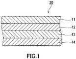
- a filter medium 20 includes a first porous PTFE membrane 11, a first air-permeable support member 12, a second porous PTFE membrane 13, and a second air-permeable support member 14.
- the first porous PTFE membrane 11, the first air-permeable support member 12, the second porous PTFE membrane 13, and the second air-permeable support member 14 are stacked in this order and are bonded to one another.
- one surface of the filter medium 20 is formed by the first porous PTFE membrane 11.
- Porous PTFE membranes generally have a smooth, slippery surface. The configuration of the present embodiment thus makes it possible, when dust is deposited on the surface of the filter medium 20, to easily remove the dust from the surface of the filter medium 20.
- the filter medium 20 is composed of four layers.
- the filter medium 20 may alternatively be composed of more than four layers.
- a filter medium composed of more than four layers can be obtained by alternately stacking porous PTFE membranes and air-permeable support members.
- the filter medium 20 has a main surface that faces upstream in the flow direction of gas to be filtered and a main surface that faces downstream in the flow direction, and the upstream main surface is formed by the first porous PTFE membrane 11.
- the downstream main surface is formed by the second air-permeable support member 14.
- the term "main surface” refers to that surface of the filter medium 20 which has the largest area.
- the parameters such as thickness, surface density, average pore diameter, and porosity of the first porous PTFE membrane 11 may be equal to those of the second porous PTFE membrane 13. This means that porous PTFE membranes of the same type (porous PTFE membranes produced using the same material under the same conditions) can be used as the first porous PTFE membrane 11 and the second porous PTFE membrane 13. It should be understood that the parameters such as thickness, surface density, average pore diameter, and porosity of the first porous PTFE membrane 11 may be different from those of the second porous PTFE membrane 13.
- a porous PTFE membrane that can be used as the first porous PTFE membrane 11 or as the second porous PTFE membrane 13 has an average pore diameter in the range of, for example, 0.01 to 100 ⁇ m or 0.01 to 50 ⁇ m.
- the porous PTFE membrane has a thickness, for example, in the range of 1 to 300 ⁇ m or 2 to 100 ⁇ m.
- the porous PTFE membrane can be produced by the following method. First, a fine PTFE powder is mixed with a solvent to prepare a paste. The paste is extruded into the form of a sheet. The resulting PTFE sheet is stretched and sintered, and thus the porous PTFE membrane is obtained. In the stretching (typically biaxial stretching) of the PTFE sheet, the area stretch ratio (a value calculated by multiplying the stretch ratio in one axial direction by the stretch ratio in a direction perpendicular to the one axial direction) is, for example, in the range of 50 to 900.
- the term "PTFE" as used herein is intended to include "modified PTFE".
- the first air-permeable support member 12 and the second air-permeable support member 14 have a sheet shape.
- the first air-permeable support member 12 and the second air-permeable support member 14 each have higher strength and higher air permeability than, for example, a porous PTFE membrane used as at least one of the first porous PTFE membrane 11 and second porous PTFE membrane 13.
- the first air-permable support member is a non-woven fabric.
- the second air-permeable support member 14 there can be used woven fabrics, non-woven fabrics, meshes, nets, and foamed materials. Among these, non-woven fabrics are most preferably used.
- the fibers constituting the non-woven fabric used may be synthetic fibers made of a polymer material such as polyolefin (such as polyethylene and polypropylene), polyester (such as polyethylene terephthalate), polyamide, acrylic, and polyimide.
- the non-woven fabric may be a composite fabric constituted by a plurality of types of fibers. Non-woven fabrics of the same type (the same product number) or of different types may be used as the first air-permeable support member 12 and the second air-permeable support member 14.
- the first air-permeable support member 12 and the second air-permeable support member 14 each have a thickness, for example, in the range of 50 to 300 ⁇ m.
- the first porous PTFE membrane 11, the first air-permeable support member 12, the second porous PTFE membrane 13, and the second air-permeable support member 14 are bonded to one another.
- the method for bonding these components is not particularly limited. These components may be bonded using an adhesive or may be bonded by thermal lamination.
- thermal lamination is suitable for the present embodiment. With the use of thermal lamination, it is easier to achieve sufficient bond strength between the porous PTFE membranes and the air-permeable support members while preventing a decrease in air permeability.
- a non-woven fabric when a non-woven fabric contains fibers made of a thermoplastic resin such as polyethylene, the non-woven fabric exhibits thermal adhesiveness at relatively low temperatures.
- a non-woven fabric and a porous PTFE membrane are placed on each other and they are subjected to a pressure under heating, part of the fibers of the non-woven fabric are melted and solidified, so that the non-woven fabric is bonded to the porous PTFE membrane.
- the bonding points are located only on the fibers of the non-woven fabric, and thus regions devoid of fibers can have air permeability.
- the non-woven fabric may be an embossed non-woven fabric.
- the first air-permeable support member is an embossed non-woven fabric.
- the embossed non-woven fabric is a non-woven fabric having one or more recessed portions and one or more projecting portions.
- the embossed non-woven fabric has higher stiffness and higher strength than an unembossed non-woven fabric as thick as the embossed non-woven fabric.
- the embossed non-woven fabric has an indented pattern or, in other words, the embossed non-woven fabric has a sea-island structure when viewed in plan. In the embossed non-woven fabric of the type shown in FIG.
- T-type embossed non-woven fabric typically has a single, continuous recessed portion and a plurality of projecting portions.
- the T-type embossed non-woven fabric may have a plurality of recessed portions separate from each other. In the embossed non-woven fabric of the type shown in FIG.
- the S-type embossed non-woven fabric typically has a plurality of recessed portions and a single, continuous projecting portion.
- the S-type embossed non-woven fabric may have a plurality of projecting portions separate from each other. With the use of these embossed non-woven fabrics, the locations of the bonding points described above are further limited, so that it is easier to achieve both high air permeability and high bond strength.
- an embossed portion of an embossed non-woven fabric is formed as a result of melting and solidification of a part of fibers of the non-woven fabric.
- the embossed portion also has air permeability; however, the air permeability of the embossed portion is lower than the air permeability of an unembossed portion.
- the air permeability of the filter medium decreases with an increase in the area of the embossed portion.
- the air permeability of the filter medium decreases with an increase in the ratio of the area of the embossed portion to the area of the embossed non-woven fabric (embossed area ratio).
- Enhancement of the bond strength between the porous PTFE membrane and the non-woven fabric requires, for example, increasing the heat applied to the porous PTFE membrane and the non-woven fabric (raising the heating temperature and/or lengthening the heating time) in the thermal lamination process. In other words, it is necessary to melt the fibers of the non-woven fabric to a greater extent.
- increasing the heat applied to the porous PTFE membrane and the non-woven fabric causes a considerable decrease in the air permeability of the filter medium.
- the filter medium when the filter medium is fabricated under the same conditions except for the use of a non-woven fabric having a large embossed area ratio, the decrease in air permeability of the filter medium can be prevented. That is, it is important to use a non-woven fabric having an embossed area ratio appropriate for the required bond strength between the porous PTFE membrane and the non-woven fabric.
- the filter medium 20 can be placed at a given location (for example, within a vacuum cleaner) in such a manner that dust will be deposited on the surface formed by the first porous PTFE membrane 11.
- a bond strength A 1 as measured by a 180° peel test, between the first porous PTFE membrane 11 and the first air-permeable support member 12 is higher than 1.2 N/25 mm.
- the filter medium 20 of the present embodiment exhibits sufficient resistance to pressure imposed by a water stream, air stream, or brush.
- the ratio of the area of a recessed portion (or the ratio of the total area of a plurality of recessed portions) of an embossed non-woven fabric serving as the first air-permeable support member 12 to the area of the embossed non-woven fabric is more than 15%.
- the bond strength A 1 between the first porous PTFE membrane 11 and the first air-permeable support member 12 is sufficiently high, but also the embossed area ratio in the non-woven fabric serving as the first air-permeable support member 12 is appropriately adjusted so that the increase in the pressure loss across the filter medium 20 due to the increase in the bond strength A 1 can be effectively prevented.
- embossed area ratio refers to the ratio of the area of a recessed portion (portion where fibers are melted) or the total area of a plurality of recessed portions to the area of the embossed non-woven fabric.
- the embossed area ratio can be calculated by the following method.
- the surface of the non-woven fabric is observed with an electron microscope (SEM) at a given magnification (for example, a magnification of 25 times).
- SEM electron microscope
- the proportion of the embossed portion(s) (recessed portion(s)) is calculated.
- the recessed portions are assumed to be circular.
- the projecting portions (unembossed portions) are assumed to be elliptical.
- the embossed area ratio in the non-woven fabric serving as the first air-permeable support member 12 can be measured, even after production of the filter medium 20, by separating the first porous PTFE membrane 11 or second porous PTFE membrane 13 from the first air-permeable support member 12. With the use of a flat roll having a flat surface in the thermal lamination process, the embossed area ratio in the non-woven fabric hardly changes even after the thermal lamination process.
- the embossed portion(s) can be distinguished from the rest of the non-woven fabric even after separation of the first porous PTFE membrane 11 or second porous PTFE membrane 13 from the first air-permeable support member 12. The same applies to the second air-permeable support member 14.
- the embossed non-woven fabric is, for example, a double-embossed non-woven fabric having two embossed surfaces.
- a double-embossed non-woven fabric is used as the first air-permeable support member 12
- the two embossed surfaces of the first air-permeable support member 12 are in contact with the first porous PTFE membrane 11 and the second porous PTFE membrane 13, respectively.
- double-embossed non-woven fabrics are used as the first air-permeable support member 12 and the second air-permeable support member 14, the use of the same material can be expected to produce a cost-reducing effect.
- the use of double-embossed non-woven fabrics reduces the occurrence of errors in manufacturing of the filter medium 20, since there is no distinction between the two sides of double-embossed non-woven fabrics.
- a single-embossed non-woven fabric having only one embossed surface may be used as the first air-permeable support member 12.
- a single-embossed non-woven fabric having only one embossed surface may be used as the second air-permeable support member 14.
- the embossed area ratio is desirably more than 20%.
- the upper limit of the embossed area ratio is not particularly defined.
- the embossed area ratio may be less than 60% or may even be less than 50%.
- Embossed non-woven fabrics include T-type embossed non-woven fabrics and S-type embossed non-woven fabrics as described with reference to FIG. 2A and FIG. 2B .
- T-type embossed non-woven fabrics FIG. 2A
- the T-type embossed non-woven fabric has the advantage of being able to be easily pleated.
- the longitudinal direction of a plurality of unembossed portions coincides with the vertical or horizontal direction.
- each pair of the unembossed portions form a T-shape.
- the T-type embossed non-woven fabric can easily be pleated when, as shown in FIG. 2C , the pleating is carried out in such a manner that the direction of the pleating folds (the direction of mountain and valley folds) coincides with the longitudinal direction of the unembossed portions 16.
- the bond strength A 1 between the first porous PTFE membrane 11 and the first air-permeable support member 12 is higher than a bond strength A 2 , as measured by the 180° peel test, between the first air-permeable support member 12 and the second porous PTFE membrane 13.
- the second porous PTFE membrane 13 is disposed between the pair of support members 12 and 14 and has no direct contact with a brush or water during cleaning of the filter medium 20. This is why the bond strength A 2 between the first air-permeable support member 12 and the second porous PTFE membrane 13 has no significant influence on the durability required for removal of dust from the surface of the filter medium 20.
- adjusting the bond strengths A 1 and A 2 to establish the above-mentioned relationship makes it possible to improve the durability of the filter medium 20 while avoiding a significant decrease in air permeability. That is, both high durability and high air permeability can be achieved.
- the bond strength A 1 between the first porous PTFE membrane 11 and the first air-permeable support member 12 is desirably 1.8 N/25 mm or more. In this case, higher durability can be imparted to the filter medium 20.
- the bond strength A 1 between the first porous PTFE membrane 11 and the first air-permeable support member 12 is 2.5 N/25 mm or less. In this case, it is possible to avoid excessively close bonding and impart sufficient air permeability to the filter medium 20.
- the filter medium 20 having a good balance between the durability and air permeability can be obtained.
- the bond strength A 2 between the first air-permeable support member 12 and the second porous PTFE membrane 13 is not particularly limited, as long as the bond strength A 2 is lower than the bond strength A 1 between the first porous PTFE membrane 11 and the first air-permeable support member 12.
- the upper limit of the bond strength A 2 is, for example, 1.6 N/25 mm.
- the lower limit of the bond strength A 2 is, for example, 0.2 N/25 mm.
- the filter medium 20 is more likely to have sufficient air permeability.
- the difference between the bond strength A 1 and the bond strength A 2 is not particularly limited either. In an example, the difference between the bond strength A 1 and the bond strength A 2 is in the range of 0.2 to 2.3 N/25 mm.
- the above values of the bond strengths A 1 and A 2 are those measured by a 180° peel test.
- the 180° peel test can be conducted by the below-described methods according to Japanese Industrial Standard, JIS Z 0237.
- the method illustrated in FIG. 3A is a method for measuring the bond strength A 1 between the first porous PTFE membrane 11 and the first air-permeable support member 12.
- the filter medium 20 is cut into a test specimen with a size of 100 mm ⁇ 25 mm.
- the test specimen has a length of 100 mm in the MD direction (MD: Machine Direction) of the first porous PTFE membrane 11 and a width of 25 mm in the TD direction (TD: Transverse Direction) of the first porous PTFE membrane 11.
- MD and TD directions correspond to those in the production of the first porous PTFE membrane 11.
- a non-bonded portion where the first porous PTFE membrane 11 and the first air-permeable support member 12 are not bonded is provided beforehand at the longitudinal end of the test specimen so that peeling can occur at the interface between the first porous PTFE membrane 11 and the first air-permeable support member 12.
- the test specimen is attached to a stainless steel plate 25 with a double-coated adhesive tape 26 (No. 500, manufactured by Nitto Denko Corporation).
- the non-bonded portion of the test specimen is then secured to a chuck 24 of a tensile tester (Autograph AG-1, manufactured by Shimadzu Corporation).
- the chuck 24 is drawn upward at a speed of 300 mm/min to cause peeling at the interface between the first porous PTFE membrane 11 and the first air-permeable support member 12, thereby measuring the 180° peel strength. Values measured initially after the start of the measurement over a length of 25 mm are ignored, and the average of the subsequently measured values (in units of N) continuously recorded for a 50-mm-long portion of the test specimen stripped off from the stainless steel plate 25 is determined as the bond strength A 1 of the filter medium 20.
- the method illustrated in FIG. 3B is a method for measuring the bond strength A 2 between the first air-permeable support member 12 and the second porous PTFE membrane 13.
- a non-bonded portion where the first air-permeable support member 12 and the second porous PTFE membrane 13 are not bonded is provided at the longitudinal end of the test specimen so that peeling can occur at the interface between the first air-permeable support member 12 and the second porous PTFE membrane 13.
- the non-bonded portion of the test specimen is secured to the chuck 24 of the tensile tester.
- the chuck 24 is drawn upward at a speed of 300 mm/min to cause peeling at the interface between the first air-permeable support member 12 and the second porous PTFE membrane 13, thereby measuring the 180° peel strength.
- the average of measured values (in units of N) continuously recorded is determined as the bond strength A 2 of the filter medium 20.
- the test specimen has a length of 100 mm in the MD direction (MD: Machine Direction) of the second porous PTFE membrane 13 and a width of 25 mm in the TD direction (TD: Transverse Direction) of the first porous PTFE membrane 11.
- MD and TD directions of the second porous PTFE membrane 13 coincide with the MD and TD directions of the first porous PTFE membrane 11.
- the pressure drop across the filter medium 20 is, for example, in the range of 50 to 400 Pa.
- the "pressure drop” refers to a pressure drop that occurs when air is allowed to pass through the filter medium 20 at a flow velocity of 5.3 cm/sec.
- the pressure drop can be measured by the following method. That is, the filter medium 20 is set to a cylindrical holder with an effective area of 100 cm 2 , and a pressure difference is created between the two sides of the filter medium 20 to allow air to pass through the filter medium 20.
- the flow velocity of the air passing through the filter medium 20 is adjusted to 5.3 cm/sec (corresponding to a flow rate of 31.8 m 3 /min) with the aid of a flowmeter, and then the pressure drop is measured with a pressure meter (manometer).
- the filter medium 20 exhibits a collection efficiency higher than 90%, for example, for particles having a particle diameter in the range of 0.1 to 0.2 ⁇ m.
- a filter medium that exhibits high collection efficiency for small particles tends to have low air permeability, and it is difficult to impart both high durability and high air permeability to such a filter medium.
- the collection efficiency can be measured by the following method. That is, the filter medium 20 is set to a cylindrical holder with an effective area of 100 cm 2 , and a pressure difference is created between the two sides of the filter medium 20 to allow gas to pass through the filter medium 20. The pressure difference is adjusted to control the liner velocity of the gas passing through the filter medium 20 to 5.3 cm/sec (corresponding to a flow rate of 31.8 m 3 /min). Next, polydisperse dioctyl phthalate (DOP) particles specified in JIS Z 8901 are introduced into the gas present upstream of the filter medium 20 in such a manner that the concentration of particles having particle diameters in a predetermined range is 10 6 particles/liter.
- DOP polydisperse dioctyl phthalate
- the concentration of the DOP particles present downstream of the filter medium 20 is then measured with a particle counter.
- the range of the diameter of the particles to be counted by the particle counter is, for example, from 0.1 to 0.2 ⁇ m.
- Polyalphaolefin (PAO) may be used instead of the DOP particles.
- the filter medium 20 may be a HEPA filter (High Efficiency Particulate Air Filter) or may be an ULPA filter (Ultra Low Penetration Air Filter). Both the HEPA filter and ULPA filter are filters specified in Japanese Industrial Standard, JIS Z 8122.
- the filter medium 20 may be pleated into a series of W-shapes.
- the pleating of the filter medium 20 can be accomplished using a known pleating machine (such as a rotary pleating machine, a reciprocating pleating machine, and a striping pleating machine).
- a known pleating machine such as a rotary pleating machine, a reciprocating pleating machine, and a striping pleating machine.
- the bond strength A 1 between the first porous PTFE membrane 11 and the first air-permeable support member 12 is higher than the bond strength A 2 between the first air-permeable support member 12 and the second porous PTFE membrane 13.
- the stiffness of the filter medium 20 is lower than in the case where the bond strength A 2 is equal to the bond strength A 1 , and thus the above pleating can more easily be carried out.
- the first porous PTFE membrane 11, the first air-permeable support member 12, the second porous PTFE membrane 13, and the second air-permeable support member 14 are individually prepared on rolls.
- the first porous PTFE membrane 11, the first air-permeable support member 12, the second porous PTFE membrane 13, and the second air-permeable support member 14 are fed from the rolls and assembled together to form a stack 20s of the membranes and members.
- the stack 20s is delivered to a pair of lamination rolls 27a and 27b and passed through the gap between the lamination rolls 27a and 27b.
- the pair of lamination rolls 27a and 27b is configured to apply heat and pressure to the stack 20s.
- the rolls 27a and 27b are configured so that the surface temperature of the roll 27a that contacts one surface of the stack 20s can be made different from the surface temperature of the roll 27b that contacts the other surface of the stack 20s.
- the lamination roll 27a is equipped with a heater, while the lamination roll 27b is not equipped with any heater.
- the lamination roll 27a is a heating roll
- the lamination roll 27b is a nip roll.
- the first porous PTFE membrane 11 contacts the lamination roll 27a and the second air-permeable support member 14 contacts the lamination roll 27b.
- the thermal lamination of the stack 20s can thus be accomplished so that the bond strength A 1 between the first porous PTFE membrane 11 and the first air-permeable support member 12 will be higher than the bond strength A 2 between the first air-permeable support member 12 and the second porous PTFE membrane 13. It is naturally important to appropriately control the conditions such as the surface temperature of the lamination roll 27a, the pressure applied to the stack 20s, and the conveyance speed of the stack 20s.
- the thermal lamination process can be carried out in two stages as shown in FIG. 4B .
- the first stage which is illustrated in the upper part of FIG. 4B
- the stack 20s is heated from both above and below by heaters 29 placed on the conveyance path, and is then directed to the gap between a roll 28a and a roll 28b.
- the roll 28a is a rotating roll
- the roll 28b is a nip roll.
- the heaters 29 are, for example, infrared heaters.
- the rolls 28a and 28b have the function of applying pressure to the stack 20s but do not have the function of applying heat to the stack 20s.
- the first porous PTFE membrane 11, the first air-permeable support member 12, the second porous PTFE membrane 13, and the second air-permeable support member 14 are provisionally bonded through the rolls 28a and 28b, thereby giving a stack 20k.
- the stack 20k is delivered to the lamination rolls 27a and 27b identical to those as described with reference to FIG. 4A .
- the lamination roll 27a for heating contacts the first porous PTFE membrane 11 of the stack 20k.
- the thermal lamination of the stack 20k can thus be accomplished so that the bond strength A 1 between the first porous PTFE membrane 11 and the first air-permeable support member 12 will be higher than the bond strength A 2 between the first air-permeable support member 12 and the second porous PTFE membrane 13.
- the first porous PTFE membrane 11 and the first air-permeable support member 12 may be preliminarily bonded loosely before the formation of the stack 20s.
- the second porous PTFE membrane 13 and the second air-permeable support member 14 may be preliminarily bonded loosely.
- a filter unit 30 includes a filter medium 20a and a support frame 22.
- the filter medium 20a is obtained by pleating of the filter medium 20 shown in FIG. 1 .
- the support frame 22 supports the outer peripheral portion of the filter medium 20a.
- the support frame 22 is made of resin or metal.
- the filter medium 20a may be fixed to the support frame 22 with an adhesive.
- the support frame 22 may be provided with a structure for fixedly holding the outer peripheral portion of the filter medium 20a.
- the outer peripheral portion of the filter medium 20a may be buried in the support frame 22. That is, the support frame 22 and the filter medium 20a may be integrally formed by insert molding.
- the filter unit 30 can be used, for example, as an exhaust filter of a vacuum cleaner.
- the vacuum cleaner 40 is a cyclone vacuum cleaner.
- the filter unit 30 of the present embodiment is applicable to a vacuum cleaner (such as a paper bag vacuum cleaner) other than cyclone vacuum cleaners.
- the vacuum cleaner 40 includes: a mechanism 31 (a cyclone or paper bag) for separating dust from intake air; a motor 32 for rotating a fan 33; and at least one filter unit 30.
- a mechanism 31 a cyclone or paper bag
- a motor 32 for rotating a fan 33
- at least one filter unit 30 In the example shown in FIG. 6 , two (a plurality of) filter units 30 are provided. One of the filter units 30 is disposed between the mechanism 31 and the motor 32 in an air flow path. The other of the filter units 30 is disposed between the motor 32 and an exhaust port (not shown) in the air flow path.
- the first porous PTFE membrane 11 is located most upstream in the flow direction of air and the second air-permeable support member 14 is located most downstream in the flow direction of air. Thus, dust is deposited mainly on the surface of the first porous PTFE membrane 11.
- One of the filter units 30 that is located more downstream serves also to collect carbon powder discharged from the motor 32.
- Each filter unit 30 is detachable from the vacuum cleaner 40. Dust deposited on the surface of each filter unit 30 (in particular, on the surface of the first porous PTFE membrane 11) can be removed, for example, by means of a brush, an air stream, or a water stream.
- a filter medium having the configuration described with reference to FIG. 1 was fabricated by the method described with reference to FIG. 4A .
- ULPA-grade porous PTFE membranes (NTF 9522-01, manufactured by Nitto Denko Corporation) were used as the first porous PTFE membrane and the second porous PTFE membrane.
- the surface temperature of the lamination roll (roll 27a) for heating was 200°C.
- a nip roll having no heater was used as the other lamination roll (roll 27b).
- the conveyance speed of the stack (stack 20s) of the first porous PTFE membrane, the first air-permeable support member, the second porous PTFE membrane, and the second air-permeable support member was 5 m/min.
- a filter medium having the configuration described with reference to FIG. 1 was fabricated by the method described with reference to FIG. 4B .
- ULPA-grade porous PTFE membranes (NTF 9522-01, manufactured by Nitto Denko Corporation) were used as the first porous PTFE membrane and the second porous PTFE membrane.
- T-type PET/PE core-sheath non-woven fabrics (T0303WDO, manufactured by UNITIKA LTD.) were used as the first air-permeable support member and the second air-permeable support member.
- a power supplied to the infrared heaters was controlled so that the stack (stack 20s) was heated at a temperature of 150°C.
- the conveyance speed of the stack was 7 m/min.
- the surface temperature of the lamination roll (roll 27a) for heating was 150°C.
- a nip roll having no heater was used as the other lamination roll (roll 27b).
- the conveyance speed of the stack (stack 20k) of the first porous PTFE membrane, the first air-permeable support member, the second porous PTFE membrane, and the second air-permeable support member was 5 m/min.
- a filter medium of Comparative Example 1 was fabricated in the same manner as in Example 1, except for using S-type PET/PE core-sheath non-woven fabrics (S0303WDO, manufactured by UNITIKA LTD.) as the first air-permeable support member and the second air-permeable support member.
- S0303WDO S-type PET/PE core-sheath non-woven fabrics
- a filter medium of Comparative Example 2 was fabricated in the same manner as in Example 2, except that, in the method described with reference to FIG. 4B , only the first stage (the upper part of FIG. 4B ) was performed using S-type PET/PE core-sheath non-woven fabrics (S0303WDO, manufactured by UNITIKA LTD.) as the first air-permeable support member and the second air-permeable support member with omission of the second stage (the lower part of FIG. 4B ).
- S-type PET/PE core-sheath non-woven fabrics S0303WDO, manufactured by UNITIKA LTD.
- a filter medium of Comparative Example 3 was fabricated in the same manner as in Example 2, except that, in the method described with reference to FIG. 4B , only the first stage (the upper part of FIG. 4B ) was performed with omission of the second stage (the lower part of FIG. 4B ).
- a five-layer filter medium including a first air-permeable support member, a first porous PTFE membrane, a second air-permeable support member, a second porous PTFE membrane, and a third air-permeable support member that were stacked in this order and bonded to one another was fabricated in the same manner as in Comparative Example 2. That is, a five-layer filter medium of Comparative Example 4 was fabricated in the same manner as in Example 2, except that, in the method described with reference to FIG. 4B , only the first stage (the upper part of FIG. 4B ) was performed with omission of the second stage (the lower part of FIG. 4B ).
- the filter medium of Comparative Example 4 corresponds to a filter medium having a configuration disclosed in FIG. 1 of Patent Literature 2.
- a durability test was conducted for the filter media of Examples and Comparative Examples by the following method. First, each of the filter media of Examples and Comparative Example was cut to give a test specimen having a length of 300 mm and a width of 900 mm. As shown in FIG. 7 , air with a pressure of 0.2 MPa was blown to a surface of the test specimen (the surface formed by a porous PTFE membrane) by an air gun 35 at an angle of 45 degrees from a point 10 cm away from the surface. While air was blown to the test specimen, the air gun 35 was slowly moved in the width direction WD of the test specimen for 10 seconds. After that, the test specimen was visually inspected.
- test for examining the ease of cleaning of the filter media of Examples and Comparative Examples was conducted by the following method. First, each of the filter media of Examples and Comparative Examples was cut to give a test specimen attachable to a circular-conical holder with an effective area of 100 cm 2 . The test specimen was set to the holder, and 0.2 g of test powder (No. 8) specified in JIS Z 8901 was spread on the surface of the filter medium. Air was then allowed to pass through the test specimen at a linear velocity of 0.2 m/min for 1 minute. Subsequently, the surface of the test specimen was washed with running water for 5 minutes to remove the powder. This procedure was repeated five times. After that, the test specimen was visually inspected.
- FIG. 8A is an optical photograph of the surface of the filter medium of Example 1 as observed after the test.
- FIG. 8B is an optical photograph of the surface of the filter medium of Comparative Example 4 as observed after the test.
- each of the filter media of Examples and Comparative Examples was subjected to a 180° peel test. Specifically, the bond strength A 1 between the first porous PTFE membrane and the first air-permeable support member (non-woven fabric) was measured by the method described with reference to FIG. 3A . The bond strength A 2 between the first air-permeable support member (non-woven fabric) and the second porous PTFE membrane was measured by the method described with reference to FIG. 3B .
- a bond strength between the first air-permeable support member (first layer) and the first porous PTFE membrane (second layer) was measured as the "bond strength A 1 " according to the method described with reference to FIG.
- the filter medium of Example 1 in which a non-woven fabric having a large embossed area ratio was used as the first air-permeable support member, exhibited a sufficiently lower pressure drop than the filter medium of Comparative Example 1 in which a non-woven fabric having a small embossed area ratio was used as the first air-permeable support member.
- Example 1 As seen by comparing Example 1 and Example 2, the two-stage lamination process described with reference to FIG. 4B successfully increased the bond strength A 1 between the first porous PTFE membrane and the first air-permeable support member while reducing the increase in the bond strength A 2 between the first air-permeable support member and the second porous PTFE membrane.
- Example 2 the filter medium of Example 2, in which a non-woven fabric having a large embossed area ratio was used as the first air-permeable support member, exhibited a sufficiently low pressure drop despite the use of the two-stage lamination process.
- Example 2 As seen by comparing Example 2 and Example 3, the difference in the embossed area ratio of the second air-permeable support member exerted no significant effect on the properties of the filter media.
- the bond strength A 1 was as low as 1.2 N/25 mm, and peeling of the porous PTFE membrane was observed in the durability test.
- the bond strength A 2 in Example 2 was approximately equal to the bond strength A 2 in Comparative Example 3. This suggests that the second stage (the lower part of FIG. 4B ) in the method described with reference to FIG. 4B is capable of preferentially increasing the bond strength A 1 while causing little increase in bond strength A 2 . That is, the method described with reference to FIG. 4B allows easy control of the bond strengths A 1 and A 2 .
- each of the filter media of Examples 1 to 3 was formed by a porous PTFE membrane.
- the surface of the filter medium of Comparative Example 4 was formed by an air-permeable support member (non-woven fabric).
- dust was not sufficiently removed by cleaning.
- the surface of each of the filter media of Comparative Examples 2 and 3 was formed by a porous PTFE membrane; however, the porous PTFE membrane was broken during cleaning because the bond strength A 1 was low.
- the bond strength A 1 of the filter medium of Comparative Example 4 was as low as 0.4 N/25 mm. However, the non-woven fabric forming the surface of the filter medium of Comparative Example 4 was not broken during cleaning.
- the increase in pressure drop was 0% for all of the filter media of Examples 1 to 3. This means that, in Examples 1 to 3, the pressure drop remained unchanged before and after the test for examining the ease of cleaning.
- the pressure drop was increased by about 6%, compared to that measured before the test for examining the ease of cleaning.
- the technique disclosed herein is applicable to various filters such as intake air filters for turbines, air filters for clean rooms, and filters for household electric appliances.
- the technique disclosed herein particularly contributes to improvement of vacuum-cleaner filters which may be frequently cleaned.
Landscapes
- Chemical & Material Sciences (AREA)
- Chemical Kinetics & Catalysis (AREA)
- Engineering & Computer Science (AREA)
- Mechanical Engineering (AREA)
- Separation Using Semi-Permeable Membranes (AREA)
- Filtering Materials (AREA)
- Laminated Bodies (AREA)
Claims (7)
- Milieu filtrant (20, 20a) comprenant une première membrane de polytétrafluoroéthylène poreuse (11), un premier élément de support perméable à l'air (12), une seconde membrane de polytétrafluoroéthylène poreuse (13) et un second élément de support perméable à l'air (14) qui sont empilés dans cet ordre et liés l'un à l'autre, dans lequel une surface du milieu filtrant (20, 20a) est formée par la première membrane de polytétrafluoroéthylène poreuse (11), une résistance d'adhésion, telle que mesurée par un essai de pelage à 180 ° conformément à JIS Z 0237, entre la première membrane de polytétrafluoroéthylène poreuse (11) et le premier élément de support perméable à l'air (12) est supérieure à 1,2 N/25 mm et est de 2,5 N/25 mm ou moins,le premier élément de support perméable à l'air (12) est un tissu non tissé gaufré ayant une ou plusieurs portions en retrait et une ou plusieurs portions saillantes, le tissu non tissé gaufré a une structure mer-îlot lorsqu'il est visualisé en plan, dans le tissu non tissé gaufré, une portion correspondant à un îlot est la portion saillante, où les fibres ne sont pas fondues, et une portion correspondant à la mer est la portion en retrait, où les fibres sont fondues, ou une portion correspondant à un îlot est la portion en retrait, où les fibres sont fondues, et une portion correspondant à la mer est la portion saillante, où les fibres ne sont pas fondues, un rapport de l'aire de la portion en retrait ou l'aire totale des portions en retrait sur l'aire du tissu non tissé gaufré servant de premier élément de support perméable à l'air (12) est supérieur à 15 %, etle rapport est déterminé en utilisant la microscopie électronique à balayage (MEB), dans lequel la proportion de la portion en retrait est calculée sur la base d'une image de MEB obtenue de la surface du tissu non tissé gaufré.
- Milieu filtrant selon la revendication 1, dans lequel
la résistance d'adhésion entre la première membrane de polytétrafluoroéthylène poreuse et le premier élément de support perméable à l'air est de 1,8 N/25 mm ou plus et 2,5 N/25 mm ou moins. - Milieu filtrant selon la revendication 1, dans lequel le rapport est inférieur à 60%.
- Milieu filtrant selon la revendication 1, dans lequel la résistance d'adhésion entre la première membrane de polytétrafluoroéthylène poreuse et le premier élément de support perméable à l'air est supérieure à une résistance d'adhésion, telle que mesurée par l'essai de pelage à 180 °, entre la première membrane de polytétrafluoroéthylène poreuse et la seconde membrane de polytétrafluoroéthylène poreuse.
- Milieu filtrant selon la revendication 1, dans lequel la première membrane de polytétrafluoroéthylène poreuse, le premier élément de support perméable à l'air, la seconde membrane de polytétrafluoroéthylène poreuse et le second élément de support perméable à l'air sont liés l'un à l'autre par stratification thermique.
- Milieu filtrant selon la revendication 1, dans lequel le milieu filtrant est plissé.
- Unité filtrante (30) comprenant :le milieu filtrant selon la revendication 1 ; etun cadre de support (22) supportant une portion périphérique externe du milieu filtrant.
Applications Claiming Priority (2)
| Application Number | Priority Date | Filing Date | Title |
|---|---|---|---|
| JP2015095109 | 2015-05-07 | ||
| PCT/JP2016/002246 WO2016178324A1 (fr) | 2015-05-07 | 2016-05-02 | Matériau filtrant pour filtre, et unité de filtre |
Publications (3)
| Publication Number | Publication Date |
|---|---|
| EP3292906A1 EP3292906A1 (fr) | 2018-03-14 |
| EP3292906A4 EP3292906A4 (fr) | 2018-10-17 |
| EP3292906B1 true EP3292906B1 (fr) | 2022-11-23 |
Family
ID=57217909
Family Applications (1)
| Application Number | Title | Priority Date | Filing Date |
|---|---|---|---|
| EP16789460.9A Active EP3292906B1 (fr) | 2015-05-07 | 2016-05-02 | Matériau filtrant pour filtre, et unité de filtre |
Country Status (7)
| Country | Link |
|---|---|
| US (1) | US10688432B2 (fr) |
| EP (1) | EP3292906B1 (fr) |
| JP (1) | JP6725311B2 (fr) |
| KR (1) | KR20180002673A (fr) |
| CN (1) | CN107530646B (fr) |
| TW (1) | TWI683695B (fr) |
| WO (1) | WO2016178324A1 (fr) |
Families Citing this family (10)
| Publication number | Priority date | Publication date | Assignee | Title |
|---|---|---|---|---|
| KR101998031B1 (ko) * | 2018-06-29 | 2019-07-08 | 닛토덴코 가부시키가이샤 | 에어 필터 유닛 및 공조기 |
| CN110406239B (zh) * | 2019-07-30 | 2021-04-16 | 淮北雷德机电科技有限公司 | 一种过滤网袋胶合装置 |
| CN110917726B (zh) * | 2019-12-12 | 2021-10-22 | 上海科格思过滤材料有限公司 | 一种新型无骨架滤料的制备方法 |
| KR20210134152A (ko) * | 2020-04-29 | 2021-11-09 | 코웨이 주식회사 | 집진 필터 및 이의 제조방법 |
| WO2022064528A1 (fr) * | 2020-09-25 | 2022-03-31 | Ashok Shukla | Ensemble filtre remplaçable multicouche et ensemble microfiltre associé à un ventilateur d'aspiration alimenté par batterie |
| WO2022196306A1 (fr) * | 2021-03-17 | 2022-09-22 | 日東電工株式会社 | Procédé de fabrication d'un film de séparation et film de séparation |
| KR20230069696A (ko) | 2021-11-12 | 2023-05-19 | (주)크린앤사이언스 | 에어 필터 여재 및 그 제조방법 |
| KR102926833B1 (ko) | 2022-12-14 | 2026-02-12 | (주)크린앤사이언스 | 초극세 데니어 부직포 지지체, 다공성 에어 필터 여재 및 그 제조방법 |
| WO2025187322A1 (fr) * | 2024-03-07 | 2025-09-12 | 日東電工株式会社 | Milieu filtrant, unité de filtre et procédé de fabrication de milieu filtrant |
| CN118548165A (zh) * | 2024-04-25 | 2024-08-27 | 东滤器材(石家庄)有限公司 | 一种用于内燃汽车发动机进气口的防涉水滤芯及制作方法 |
Family Cites Families (17)
| Publication number | Priority date | Publication date | Assignee | Title |
|---|---|---|---|---|
| US5993943A (en) * | 1987-12-21 | 1999-11-30 | 3M Innovative Properties Company | Oriented melt-blown fibers, processes for making such fibers and webs made from such fibers |
| US6150005A (en) * | 1997-04-15 | 2000-11-21 | International Paper Company | Synthetic paper |
| JP5051944B2 (ja) * | 2001-03-16 | 2012-10-17 | 日東電工株式会社 | エアフィルタ用濾材およびその製造方法 |
| JP3793130B2 (ja) * | 2002-09-11 | 2006-07-05 | 日東電工株式会社 | 集塵機用フィルターおよびその製造方法 |
| KR100456167B1 (ko) * | 2002-11-22 | 2004-11-09 | 삼성광주전자 주식회사 | 진공청소기용 집진필터 및 이를 구비하는 진공청소기 |
| JP4213485B2 (ja) * | 2003-02-13 | 2009-01-21 | 日東電工株式会社 | 通気性複合材の製造方法 |
| JP2005246233A (ja) * | 2004-03-04 | 2005-09-15 | Nitto Denko Corp | 掃除機用エアフィルタ濾材およびそれを用いた掃除機用エアフィルタユニット |
| WO2007088824A1 (fr) | 2006-02-01 | 2007-08-09 | Toray Industries, Inc. | Non-tisse destine a des filtres et son procede de production |
| JP5207694B2 (ja) * | 2007-09-20 | 2013-06-12 | 日本ゴア株式会社 | 延伸多孔質ポリテトラフルオロエチレンフィルム積層ガスケットシート及びこのガスケットシートから構成されるガスケット |
| JP5425388B2 (ja) * | 2007-10-19 | 2014-02-26 | 日本ゴア株式会社 | エアフィルター及びこのエアフィルターを用いた掃除機用エアフィルター |
| JP5608323B2 (ja) * | 2007-11-14 | 2014-10-15 | 日東電工株式会社 | フィルタ濾材とその製造方法ならびにフィルタユニット |
| JP2010142746A (ja) * | 2008-12-19 | 2010-07-01 | Toyobo Co Ltd | フィルター用支持体およびそれを用いたフィルター |
| DE102010010591A1 (de) * | 2010-03-08 | 2011-09-08 | Mn-Beteiligungs Gmbh | Abstandshalter für Filtrationsvorrichtungen |
| HUE042737T2 (hu) * | 2010-06-25 | 2019-07-29 | Toray Industries | Kompozit porózus membrán, eljárás kompozit porózus membrán elõállítására és akkumulátor-elválasztóelem ennek alkalmazásával |
| JP2012228687A (ja) * | 2012-05-31 | 2012-11-22 | Nitto Denko Corp | エアフィルタ用濾材およびその製造方法 |
| US20140231340A1 (en) | 2013-02-15 | 2014-08-21 | Pall Corporation | Composite including ptfe membrane |
| JP6292920B2 (ja) * | 2013-03-29 | 2018-03-14 | 日東電工株式会社 | エアフィルタ濾材の製造方法、エアフィルタ濾材及びエアフィルタパック |
-
2016
- 2016-05-02 EP EP16789460.9A patent/EP3292906B1/fr active Active
- 2016-05-02 CN CN201680025740.8A patent/CN107530646B/zh active Active
- 2016-05-02 JP JP2016092710A patent/JP6725311B2/ja active Active
- 2016-05-02 KR KR1020177032091A patent/KR20180002673A/ko not_active Ceased
- 2016-05-02 US US15/567,722 patent/US10688432B2/en not_active Expired - Fee Related
- 2016-05-02 WO PCT/JP2016/002246 patent/WO2016178324A1/fr not_active Ceased
- 2016-05-05 TW TW105113902A patent/TWI683695B/zh not_active IP Right Cessation
Also Published As
| Publication number | Publication date |
|---|---|
| KR20180002673A (ko) | 2018-01-08 |
| US10688432B2 (en) | 2020-06-23 |
| JP6725311B2 (ja) | 2020-07-15 |
| EP3292906A1 (fr) | 2018-03-14 |
| JP2016209870A (ja) | 2016-12-15 |
| CN107530646B (zh) | 2020-09-25 |
| US20180104637A1 (en) | 2018-04-19 |
| WO2016178324A1 (fr) | 2016-11-10 |
| TW201707766A (zh) | 2017-03-01 |
| EP3292906A4 (fr) | 2018-10-17 |
| CN107530646A (zh) | 2018-01-02 |
| TWI683695B (zh) | 2020-02-01 |
Similar Documents
| Publication | Publication Date | Title |
|---|---|---|
| EP3292906B1 (fr) | Matériau filtrant pour filtre, et unité de filtre | |
| EP3275531B1 (fr) | Matériau filtrant pour filtre, et unité de filtre | |
| US6808553B2 (en) | Filter medium for turbine and methods of using and producing the same | |
| EP0707033B1 (fr) | Membrane de polytetrafluoroethylene poreuse composite | |
| US20100269464A1 (en) | Filter medium and method of manufacturing the same and filter unit | |
| JP5784458B2 (ja) | エアフィルタ濾材 | |
| EP3520874B1 (fr) | Matériau de filtre à air, bloc de filtre à air et unité de filtre à air | |
| JP2002273126A (ja) | エアフィルタ用濾材およびその製造方法 | |
| CN105188878A (zh) | 空气过滤器滤材的制造方法、空气过滤器滤材及空气过滤器部件 | |
| JP3761172B2 (ja) | エアフィルタ用濾材、その使用方法、エアフィルタユニットおよび通気性支持材 | |
| JP2002370020A (ja) | タービン用吸気フィルタ濾材およびその使用方法と製造方法 | |
| JP2017133120A (ja) | 不織布、ならびにそれを具備する集塵フィルタ、微生物または生物組織の培地、およびコスメティック用品 | |
| JP2002346319A (ja) | タービン用吸気フィルタ濾材 | |
| US12440794B2 (en) | Air filter medium, filter pleat pack, and air filter unit | |
| EP4218983A1 (fr) | Milieu filtrant de filtre à air, paquet de plis de filtre, et unité de filtre à air | |
| JP2002370009A (ja) | タービン用吸気フィルタ濾材およびその使用方法 | |
| WO2025187322A1 (fr) | Milieu filtrant, unité de filtre et procédé de fabrication de milieu filtrant | |
| EP4218982A1 (fr) | Élément de filtration de filtre à air, pack de plis de filtre et unité de filtre à air |
Legal Events
| Date | Code | Title | Description |
|---|---|---|---|
| STAA | Information on the status of an ep patent application or granted ep patent |
Free format text: STATUS: THE INTERNATIONAL PUBLICATION HAS BEEN MADE |
|
| PUAI | Public reference made under article 153(3) epc to a published international application that has entered the european phase |
Free format text: ORIGINAL CODE: 0009012 |
|
| STAA | Information on the status of an ep patent application or granted ep patent |
Free format text: STATUS: REQUEST FOR EXAMINATION WAS MADE |
|
| 17P | Request for examination filed |
Effective date: 20171026 |
|
| AK | Designated contracting states |
Kind code of ref document: A1 Designated state(s): AL AT BE BG CH CY CZ DE DK EE ES FI FR GB GR HR HU IE IS IT LI LT LU LV MC MK MT NL NO PL PT RO RS SE SI SK SM TR |
|
| AX | Request for extension of the european patent |
Extension state: BA ME |
|
| DAV | Request for validation of the european patent (deleted) | ||
| DAX | Request for extension of the european patent (deleted) | ||
| A4 | Supplementary search report drawn up and despatched |
Effective date: 20180917 |
|
| RIC1 | Information provided on ipc code assigned before grant |
Ipc: B01D 63/14 20060101ALI20180911BHEP Ipc: B01D 63/00 20060101ALI20180911BHEP Ipc: B01D 39/16 20060101ALI20180911BHEP Ipc: B01D 69/12 20060101ALI20180911BHEP Ipc: A47L 9/12 20060101ALI20180911BHEP Ipc: B01D 71/36 20060101AFI20180911BHEP |
|
| STAA | Information on the status of an ep patent application or granted ep patent |
Free format text: STATUS: EXAMINATION IS IN PROGRESS |
|
| 17Q | First examination report despatched |
Effective date: 20210215 |
|
| GRAP | Despatch of communication of intention to grant a patent |
Free format text: ORIGINAL CODE: EPIDOSNIGR1 |
|
| STAA | Information on the status of an ep patent application or granted ep patent |
Free format text: STATUS: GRANT OF PATENT IS INTENDED |
|
| INTG | Intention to grant announced |
Effective date: 20220622 |
|
| RIN1 | Information on inventor provided before grant (corrected) |
Inventor name: WADA, SHIHO |
|
| GRAS | Grant fee paid |
Free format text: ORIGINAL CODE: EPIDOSNIGR3 |
|
| GRAA | (expected) grant |
Free format text: ORIGINAL CODE: 0009210 |
|
| STAA | Information on the status of an ep patent application or granted ep patent |
Free format text: STATUS: THE PATENT HAS BEEN GRANTED |
|
| AK | Designated contracting states |
Kind code of ref document: B1 Designated state(s): AL AT BE BG CH CY CZ DE DK EE ES FI FR GB GR HR HU IE IS IT LI LT LU LV MC MK MT NL NO PL PT RO RS SE SI SK SM TR |
|
| REG | Reference to a national code |
Ref country code: GB Ref legal event code: FG4D |
|
| REG | Reference to a national code |
Ref country code: CH Ref legal event code: EP |
|
| REG | Reference to a national code |
Ref country code: DE Ref legal event code: R096 Ref document number: 602016076490 Country of ref document: DE |
|
| REG | Reference to a national code |
Ref country code: AT Ref legal event code: REF Ref document number: 1532800 Country of ref document: AT Kind code of ref document: T Effective date: 20221215 |
|
| REG | Reference to a national code |
Ref country code: IE Ref legal event code: FG4D |
|
| REG | Reference to a national code |
Ref country code: LT Ref legal event code: MG9D |
|
| REG | Reference to a national code |
Ref country code: NL Ref legal event code: MP Effective date: 20221123 |
|
| REG | Reference to a national code |
Ref country code: AT Ref legal event code: MK05 Ref document number: 1532800 Country of ref document: AT Kind code of ref document: T Effective date: 20221123 |
|
| PG25 | Lapsed in a contracting state [announced via postgrant information from national office to epo] |
Ref country code: SE Free format text: LAPSE BECAUSE OF FAILURE TO SUBMIT A TRANSLATION OF THE DESCRIPTION OR TO PAY THE FEE WITHIN THE PRESCRIBED TIME-LIMIT Effective date: 20221123 Ref country code: PT Free format text: LAPSE BECAUSE OF FAILURE TO SUBMIT A TRANSLATION OF THE DESCRIPTION OR TO PAY THE FEE WITHIN THE PRESCRIBED TIME-LIMIT Effective date: 20230323 Ref country code: NO Free format text: LAPSE BECAUSE OF FAILURE TO SUBMIT A TRANSLATION OF THE DESCRIPTION OR TO PAY THE FEE WITHIN THE PRESCRIBED TIME-LIMIT Effective date: 20230223 Ref country code: LT Free format text: LAPSE BECAUSE OF FAILURE TO SUBMIT A TRANSLATION OF THE DESCRIPTION OR TO PAY THE FEE WITHIN THE PRESCRIBED TIME-LIMIT Effective date: 20221123 Ref country code: FI Free format text: LAPSE BECAUSE OF FAILURE TO SUBMIT A TRANSLATION OF THE DESCRIPTION OR TO PAY THE FEE WITHIN THE PRESCRIBED TIME-LIMIT Effective date: 20221123 Ref country code: ES Free format text: LAPSE BECAUSE OF FAILURE TO SUBMIT A TRANSLATION OF THE DESCRIPTION OR TO PAY THE FEE WITHIN THE PRESCRIBED TIME-LIMIT Effective date: 20221123 Ref country code: AT Free format text: LAPSE BECAUSE OF FAILURE TO SUBMIT A TRANSLATION OF THE DESCRIPTION OR TO PAY THE FEE WITHIN THE PRESCRIBED TIME-LIMIT Effective date: 20221123 |
|
| PG25 | Lapsed in a contracting state [announced via postgrant information from national office to epo] |
Ref country code: RS Free format text: LAPSE BECAUSE OF FAILURE TO SUBMIT A TRANSLATION OF THE DESCRIPTION OR TO PAY THE FEE WITHIN THE PRESCRIBED TIME-LIMIT Effective date: 20221123 Ref country code: PL Free format text: LAPSE BECAUSE OF FAILURE TO SUBMIT A TRANSLATION OF THE DESCRIPTION OR TO PAY THE FEE WITHIN THE PRESCRIBED TIME-LIMIT Effective date: 20221123 Ref country code: LV Free format text: LAPSE BECAUSE OF FAILURE TO SUBMIT A TRANSLATION OF THE DESCRIPTION OR TO PAY THE FEE WITHIN THE PRESCRIBED TIME-LIMIT Effective date: 20221123 Ref country code: IS Free format text: LAPSE BECAUSE OF FAILURE TO SUBMIT A TRANSLATION OF THE DESCRIPTION OR TO PAY THE FEE WITHIN THE PRESCRIBED TIME-LIMIT Effective date: 20230323 Ref country code: HR Free format text: LAPSE BECAUSE OF FAILURE TO SUBMIT A TRANSLATION OF THE DESCRIPTION OR TO PAY THE FEE WITHIN THE PRESCRIBED TIME-LIMIT Effective date: 20221123 Ref country code: GR Free format text: LAPSE BECAUSE OF FAILURE TO SUBMIT A TRANSLATION OF THE DESCRIPTION OR TO PAY THE FEE WITHIN THE PRESCRIBED TIME-LIMIT Effective date: 20230224 |
|
| PG25 | Lapsed in a contracting state [announced via postgrant information from national office to epo] |
Ref country code: NL Free format text: LAPSE BECAUSE OF FAILURE TO SUBMIT A TRANSLATION OF THE DESCRIPTION OR TO PAY THE FEE WITHIN THE PRESCRIBED TIME-LIMIT Effective date: 20221123 |
|
| PG25 | Lapsed in a contracting state [announced via postgrant information from national office to epo] |
Ref country code: SM Free format text: LAPSE BECAUSE OF FAILURE TO SUBMIT A TRANSLATION OF THE DESCRIPTION OR TO PAY THE FEE WITHIN THE PRESCRIBED TIME-LIMIT Effective date: 20221123 Ref country code: RO Free format text: LAPSE BECAUSE OF FAILURE TO SUBMIT A TRANSLATION OF THE DESCRIPTION OR TO PAY THE FEE WITHIN THE PRESCRIBED TIME-LIMIT Effective date: 20221123 Ref country code: EE Free format text: LAPSE BECAUSE OF FAILURE TO SUBMIT A TRANSLATION OF THE DESCRIPTION OR TO PAY THE FEE WITHIN THE PRESCRIBED TIME-LIMIT Effective date: 20221123 Ref country code: DK Free format text: LAPSE BECAUSE OF FAILURE TO SUBMIT A TRANSLATION OF THE DESCRIPTION OR TO PAY THE FEE WITHIN THE PRESCRIBED TIME-LIMIT Effective date: 20221123 Ref country code: CZ Free format text: LAPSE BECAUSE OF FAILURE TO SUBMIT A TRANSLATION OF THE DESCRIPTION OR TO PAY THE FEE WITHIN THE PRESCRIBED TIME-LIMIT Effective date: 20221123 |
|
| PGFP | Annual fee paid to national office [announced via postgrant information from national office to epo] |
Ref country code: FR Payment date: 20230517 Year of fee payment: 8 |
|
| REG | Reference to a national code |
Ref country code: DE Ref legal event code: R097 Ref document number: 602016076490 Country of ref document: DE |
|
| PG25 | Lapsed in a contracting state [announced via postgrant information from national office to epo] |
Ref country code: SK Free format text: LAPSE BECAUSE OF FAILURE TO SUBMIT A TRANSLATION OF THE DESCRIPTION OR TO PAY THE FEE WITHIN THE PRESCRIBED TIME-LIMIT Effective date: 20221123 Ref country code: AL Free format text: LAPSE BECAUSE OF FAILURE TO SUBMIT A TRANSLATION OF THE DESCRIPTION OR TO PAY THE FEE WITHIN THE PRESCRIBED TIME-LIMIT Effective date: 20221123 |
|
| PLBE | No opposition filed within time limit |
Free format text: ORIGINAL CODE: 0009261 |
|
| STAA | Information on the status of an ep patent application or granted ep patent |
Free format text: STATUS: NO OPPOSITION FILED WITHIN TIME LIMIT |
|
| PGFP | Annual fee paid to national office [announced via postgrant information from national office to epo] |
Ref country code: GB Payment date: 20230517 Year of fee payment: 8 |
|
| 26N | No opposition filed |
Effective date: 20230824 |
|
| PG25 | Lapsed in a contracting state [announced via postgrant information from national office to epo] |
Ref country code: SI Free format text: LAPSE BECAUSE OF FAILURE TO SUBMIT A TRANSLATION OF THE DESCRIPTION OR TO PAY THE FEE WITHIN THE PRESCRIBED TIME-LIMIT Effective date: 20221123 |
|
| REG | Reference to a national code |
Ref country code: CH Ref legal event code: PL |
|
| PG25 | Lapsed in a contracting state [announced via postgrant information from national office to epo] |
Ref country code: MC Free format text: LAPSE BECAUSE OF FAILURE TO SUBMIT A TRANSLATION OF THE DESCRIPTION OR TO PAY THE FEE WITHIN THE PRESCRIBED TIME-LIMIT Effective date: 20221123 |
|
| REG | Reference to a national code |
Ref country code: BE Ref legal event code: MM Effective date: 20230531 |
|
| PG25 | Lapsed in a contracting state [announced via postgrant information from national office to epo] |
Ref country code: MC Free format text: LAPSE BECAUSE OF FAILURE TO SUBMIT A TRANSLATION OF THE DESCRIPTION OR TO PAY THE FEE WITHIN THE PRESCRIBED TIME-LIMIT Effective date: 20221123 Ref country code: LU Free format text: LAPSE BECAUSE OF NON-PAYMENT OF DUE FEES Effective date: 20230502 Ref country code: LI Free format text: LAPSE BECAUSE OF NON-PAYMENT OF DUE FEES Effective date: 20230531 Ref country code: CH Free format text: LAPSE BECAUSE OF NON-PAYMENT OF DUE FEES Effective date: 20230531 |
|
| REG | Reference to a national code |
Ref country code: IE Ref legal event code: MM4A |
|
| PG25 | Lapsed in a contracting state [announced via postgrant information from national office to epo] |
Ref country code: IE Free format text: LAPSE BECAUSE OF NON-PAYMENT OF DUE FEES Effective date: 20230502 |
|
| PG25 | Lapsed in a contracting state [announced via postgrant information from national office to epo] |
Ref country code: IE Free format text: LAPSE BECAUSE OF NON-PAYMENT OF DUE FEES Effective date: 20230502 |
|
| PG25 | Lapsed in a contracting state [announced via postgrant information from national office to epo] |
Ref country code: IT Free format text: LAPSE BECAUSE OF FAILURE TO SUBMIT A TRANSLATION OF THE DESCRIPTION OR TO PAY THE FEE WITHIN THE PRESCRIBED TIME-LIMIT Effective date: 20221123 Ref country code: BE Free format text: LAPSE BECAUSE OF NON-PAYMENT OF DUE FEES Effective date: 20230531 |
|
| PG25 | Lapsed in a contracting state [announced via postgrant information from national office to epo] |
Ref country code: BG Free format text: LAPSE BECAUSE OF FAILURE TO SUBMIT A TRANSLATION OF THE DESCRIPTION OR TO PAY THE FEE WITHIN THE PRESCRIBED TIME-LIMIT Effective date: 20221123 |
|
| PG25 | Lapsed in a contracting state [announced via postgrant information from national office to epo] |
Ref country code: BG Free format text: LAPSE BECAUSE OF FAILURE TO SUBMIT A TRANSLATION OF THE DESCRIPTION OR TO PAY THE FEE WITHIN THE PRESCRIBED TIME-LIMIT Effective date: 20221123 |
|
| GBPC | Gb: european patent ceased through non-payment of renewal fee |
Effective date: 20240502 |
|
| PG25 | Lapsed in a contracting state [announced via postgrant information from national office to epo] |
Ref country code: FR Free format text: LAPSE BECAUSE OF NON-PAYMENT OF DUE FEES Effective date: 20240531 |
|
| PG25 | Lapsed in a contracting state [announced via postgrant information from national office to epo] |
Ref country code: GB Free format text: LAPSE BECAUSE OF NON-PAYMENT OF DUE FEES Effective date: 20240502 |
|
| PGFP | Annual fee paid to national office [announced via postgrant information from national office to epo] |
Ref country code: DE Payment date: 20250402 Year of fee payment: 10 |
|
| PG25 | Lapsed in a contracting state [announced via postgrant information from national office to epo] |
Ref country code: CY Free format text: LAPSE BECAUSE OF FAILURE TO SUBMIT A TRANSLATION OF THE DESCRIPTION OR TO PAY THE FEE WITHIN THE PRESCRIBED TIME-LIMIT; INVALID AB INITIO Effective date: 20160502 |
|
| PG25 | Lapsed in a contracting state [announced via postgrant information from national office to epo] |
Ref country code: HU Free format text: LAPSE BECAUSE OF FAILURE TO SUBMIT A TRANSLATION OF THE DESCRIPTION OR TO PAY THE FEE WITHIN THE PRESCRIBED TIME-LIMIT; INVALID AB INITIO Effective date: 20160502 |
|
| PG25 | Lapsed in a contracting state [announced via postgrant information from national office to epo] |
Ref country code: TR Free format text: LAPSE BECAUSE OF FAILURE TO SUBMIT A TRANSLATION OF THE DESCRIPTION OR TO PAY THE FEE WITHIN THE PRESCRIBED TIME-LIMIT Effective date: 20221123 |