EP3292931A1 - Outil, notamment pour l'usinage de pièces à enlèvement de copeaux - Google Patents
Outil, notamment pour l'usinage de pièces à enlèvement de copeaux Download PDFInfo
- Publication number
- EP3292931A1 EP3292931A1 EP17182281.0A EP17182281A EP3292931A1 EP 3292931 A1 EP3292931 A1 EP 3292931A1 EP 17182281 A EP17182281 A EP 17182281A EP 3292931 A1 EP3292931 A1 EP 3292931A1
- Authority
- EP
- European Patent Office
- Prior art keywords
- pin
- clamping
- clamping claw
- tool according
- pressure
- Prior art date
- Legal status (The legal status is an assumption and is not a legal conclusion. Google has not performed a legal analysis and makes no representation as to the accuracy of the status listed.)
- Granted
Links
Images
Classifications
-
- B—PERFORMING OPERATIONS; TRANSPORTING
- B23—MACHINE TOOLS; METAL-WORKING NOT OTHERWISE PROVIDED FOR
- B23B—TURNING; BORING
- B23B29/00—Holders for non-rotary cutting tools; Boring bars or boring heads; Accessories for tool holders
- B23B29/04—Tool holders for a single cutting tool
- B23B29/046—Tool holders for a single cutting tool with an intermediary toolholder
Definitions
- the present invention relates to a tool, in particular for the machining of workpieces, according to the preamble of claim 1.
- Such tools have been known for some time in various embodiments. They include a tool holder (hereinafter referred to as a basic holder), in the end of a replaceable head is received and clamped therein.
- the replaceable head carries a cutting edge which is rotatably and / or removably mounted. It is also conceivable that the cutting edge is formed in one piece with the interchangeable head in the context of the present invention.
- the interchangeable head is clamped in its seat in the recess in such a way that the cutting edge is held securely in a defined position during workpiece machining.
- the replaceable head is provided in this case with a pin which is inserted into a corresponding recess at the end of the base holder.
- corresponding positioning elements can be attached to the basic holder, such as pins which engage positively in corresponding recesses in the interchangeable head, or, for example, a contact surface for receiving the interchangeable head.
- the clamping screw is tightened to fasten the base holder with a predetermined torque laterally against the pin, so transversely to the insertion direction of the same, so that a predetermined clamping force acts.
- the clamping screw is simply released by means of a corresponding tool, and the pin is pulled out of the recess.
- EP 3 031 556 A1 shows a tool holder in which a replaceable head is held by a clamping lever. When clamping the clamping lever, a pin is pressed into a recess in the removable head. In fact, however, this type of attachment does not solve the above-mentioned problems, and permanent stable positioning of the head is not achieved.
- the means for clamping the pin in the recess of a clamping claw which is mounted laterally on the base holder.
- This clamping claw can be clamped against the pin. This is done by a screw which can be screwed into the basic holder.
- the pin has at least one lateral bearing surface, which is provided for receiving a correspondingly formed pressure surface or pressing edge on the clamping claw.
- a correspondingly formed contact surface can lie flat on the support surface of the pin, so that the contact pressure is transferred surface by the clamping claw on the pin.
- a line support of a pressure edge of the clamping claw on the pressure surface is sufficient to ensure the improved pressure transmission.
- This surface conditioning or line conditioning the pressure surface or pressure on the bearing surface of the pin prevents rotation of the pin in its recess and provides a much better transmission of contact pressure than the point system of a clamping screw.
- the tension exerted during the tightening of the screw is also transmitted with a favorable lever to the journal whose bearing surface is located radially away from the screw axis. This lever maintains a certain elastic tension during workpiece machining, which reliably holds the replaceable head in position even when vibrations occur.
- the support surface is substantially transverse to the insertion direction of the pin and is inclined relative to this. In this way it can be achieved that when tightening the clamping claw, the introduced pressure force is deflected into a tensile force for pulling the pin in its insertion direction. In other words, the pin is pulled automatically when tightening the clamping claw in the recess. Inclination and course of the support surface are to be chosen expediently.
- the bearing surface of the pin limits a groove provided in the surface of the pin, which runs transversely to the insertion direction of the pin.
- This may be, for example, a notch having at least one support surface on which the pressure surface or pressure edge of the clamping claw can rest.
- the support surface limits the groove on the side facing the insertion direction of the pin side.
- the groove has a wedge-shaped cross-section.
- the clamping claw carries a projection pointing to the pin, on which the pressure surface or pressure edge is provided.
- the base holder has a lateral recess for receiving the clamping claw. In the stressed state, the clamping claw can then be recessed in the basic holder.
- the clamping claw at the end to which the projection is attached to an end face or end edge, which rests against a recess bounding the end wall.
- a pressure surface for resting on the support surface is provided on the clamping claw, preferably the end surface or front edge and this pressure surface run in a wedge shape toward one another.
- the end face or end edge and the pressure surface together form a clamping wedge, which is supported on one of the screw facing wedge flank in the groove of the pin and on the opposite wedge surface on the end wall of the recess.
- the pin is cylindrical.
- the base holder has a further bearing surface for receiving a provided on the clamping claw counter-pressure surface, which lies opposite the pressure surface with respect to the screw axis.
- the clamping claw is then pressed in this case with its pressure surface against the support surface of the pin, as already described above, while arranged opposite the screw counter-pressure surface forms an abutment over which the clamping claw is supported on the body of the base holder.
- the leverage can be further improved.
- the pressing surface and the counter-pressure surface of the clamping claw are attached to first and second end portions of the clamping claws which extend in opposite directions from the screw axis.
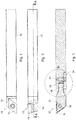
- Fig. 1 shows a tool 10 for machining workpiece machining.
- the tool comprises a base holder 12 and a replaceable head 14 replaceably mounted at one end of the base holder 12 (in FIG Fig. 1 at the left end).
- the replaceable head 14 carries a cutting edge 16, which is used in the actual sense for cutting workpiece machining.
- the tool 10 is intended to be fixedly clamped in a dedicated device of a machine tool, such that a predetermined precise positioning of the cutting edge 16 is defined.
- a dedicated device of a machine tool such that a predetermined precise positioning of the cutting edge 16 is defined.
- the replaceable head 14 can be exchanged together with the cutting edge 16, while the base holder 12 itself remains clamped. This facilitates the replacement process and shortens the set-up times of the machine tool.
- the tool 10 off Fig. 1 is in Fig. 2 shown in a position in which it is rotated by 90 ° about the main axis of the base holder 12.
- Fig. 3 shows a longitudinal section along the plane AA in Fig. 2 and thus demonstrates the internal structure of the tool 10, in particular the construction of the receptacle of the replaceable head 14 in the base holder 12 and the means for clamping the replaceable head 14 in the inserted position.
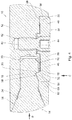
- Fig. 4 shows details Fig. 3 in an enlarged view.
- the replaceable head 14 has at its end facing the base holder 12 a pin 18 which is inserted into a correspondingly shaped recess 20 at the corresponding end of the base holder 12.
- the pin 18 is substantially cylindrical and is connected to the free end 22 of the interchangeable head 14 carrying the blade 16 by a frusto-conical shoulder 24.
- the diameter of the replaceable head 14 tapers towards the pin 18.
- the recess 20 for receiving the pin 18 is formed as a blind bore.
- the pin can thus be easily inserted into the recess 20 until the outer surface of the frusto-conical projection 24 abuts against a correspondingly shaped funnel-shaped inner surface 26 of the base holder 12, which adjoins the recess 20.
- the fully inserted position of the pin 18 in the recess 20 is shown in each case.
- the pin 18 has a laterally disposed groove 28 which extends transversely to the insertion direction B of the pin.
- This insertion direction B corresponds in the representation of Fig. 3 and 4 the direction to the right, while the groove 28 is located on the lower side of the pin 18.
- the groove 28 is a wedge-shaped notch.
- One of the wedge surfaces, namely the one which faces the insertion end of the pin 18, forms a support surface 30 for receiving a correspondingly formed contact surface 32 of a clamping claw 34, which is inserted laterally into the basic holder 12.
- This insertion direction C is in Fig. 4 indicated by an arrow.
- the support surface 30 is located in a plane which extends substantially transversely to the insertion direction B of the pin 18 and with respect to this and the insertion direction C of the clamping claw 34 is slightly inclined.
- the clamping claw 34 comprises an elongate body 36, which rests in a lateral recess 38 for receiving the clamping claw 34. In the clamped state, the clamping claw 34 is almost completely sunk into the base holder 12. Through the clamping claw 34 therethrough, a screw 40 which is screwed into an internal thread 42 in the base body 12 extends.
- the screw axis of the screw 40 extends transversely to the main axis of the main body 12 and transversely to the insertion direction B of the pin 18 and to its major axis. It is arranged in an imaginary extension of the recess 20, ie with respect to the insertion direction B of the pin 18 behind the end of the corresponding blind hole.
- the head 44 of the screw 40 is held freely rotatable. If the clamping claw 34 in the recess 38, the screw 40 can be screwed into the internal thread 42, while their head 44 rotates freely in the body 36. The clamping claw 34 is pulled in this way in their insertion direction C in the recess 38 into it.
- the head 44 of the screw 40 is also provided with an external thread, which is inserted into a corresponding internal thread in the clamping claw 34 and has an opposite direction of rotation.
- the screw 40 is screwed into the internal thread 42 of the main body 12, this causes an additional movement of the clamping claw 34 with respect to the screw 40 into the recess 38.
- the body 36 of the cleat 34 includes two end portions, namely, a first longer end portion 46 and a second shorter end portion 48 extending in opposite directions from the screw axis.
- the first end portion 46 extends from the screw axis parallel to the pin 18, while the second end portion 36 facing away from the pin 18.
- the first end portion 46 is located in a part of the recess 38, which is separated from the recess 20 for receiving the pin 18 by a wall 50.
- the wall 50 has an opening 52, through which the recess 38, in which the clamping claw 34 rests, and the recess 20 for receiving the pin 18 are connected.
- the projection 54 is attached to the end of the first end portion 46 and facing the pin 18.
- the projection 54 has a wedge-shaped cross-section, corresponding to the wedge shape of the groove 28, and extends into the groove 28 inside.
- the projection 54 carries on the wedge flank facing the screw 40 the already mentioned contact surface 32 of the clamping claw 34. This pressure surface 32 is, as well as the support surface 30 in the groove 28, flat and flat.
- a comparable effect can be achieved by a pressure edge, which is mounted instead of the pressure surface 32 to the pointing to the screw 40 inside of the projection 54 and extends transversely to the insertion direction B of the pin 18 and transverse to the insertion direction C of the clamping claw 38, ie in the Presentation in Fig. 4 perpendicular to the plane of the drawing.
- the projection 54 is then along this pressure edge on the support surface 30, so that a line support is achieved.
- the pressure edge slides on the inclined support surface 30 deeper into the groove 28, and the pressure force is in a pulling force to pull of the pin 18 diverted into the recess 20, as described above.
- This embodiment in which the pressure is transmitted along a support line of a pressure edge instead of a surface pressure, is not shown in the figures.
- the clamping claw 34 has an end face 60 which rests against an end wall 62 delimiting the recess 38.
- the cross section in Fig. 4 extends the end face 60 perpendicular to the insertion direction B of the pin 18 along the insertion direction C of the clamping claw 38.
- the pressure surface 32 is thus inclined relative to the end face 60, such that the pressure surface 32 and the end face 60 on the two opposite sides of the projection 54th wedge-shaped in the direction of the pin 18, ie in an insertion direction C of the clamping claw 38 converge toward each other and form a clamping wedge at the corresponding end of the clamping claw 38.
- the end face 60 at the first end portion 46 of the clamping claw 34 can also be replaced by an end edge in an embodiment not shown, which bears against the end wall 62 and perpendicular to the insertion direction B of the pin 18 along the insertion direction C of the clamping claw 38 extends, that is as shown of the cross section of the end face 60 in FIG Fig. 4 , In this case, a line pressure between the end edge and the end wall 62 is achieved at the first end portion 46 of the clamping claw 34.
- a front edge is provided for resting on the end wall 62 and on the opposite side of the projection 54 a pressure edge instead of the pressure surface 32 for resting on the support surface 30 of the pin 18th , that is, on both sides of the projection, a line pressure is achieved.
- the pressure edge and the end edge in this case extend perpendicular to each other.
- the opposite second end portion 48 of the clamping claw 34 carries on the base holder 12 side facing a counter-pressure surface 56 for support on a further support surface 58 on the base holder 12, namely on the bottom of the recess 38, the opening 52 opposite.
- This additional bearing surface 58 on the base holder 12 serves as an abutment during clamping of the clamping claw 34 against the pin 18, as described above. Namely, when clamping the clamping claw 34, the body 36 forms a lever which extends between the opposite ends of the end portions 46,48. As a result, a good initiation of the wedge tension on the bearing surface 30 on the pin 18 is ensured.
- both wedge surfaces of the projection 54 serve as pressure surfaces for resting on corresponding bearing surfaces in the groove of the pin.
- cross sections of the groove and the projection may be used which deviate from a wedge shape.
- the cutting edge 16 need not be rotatably or interchangeably arranged on the replaceable head 14, but the replaceable head 14 may be integrally connected to a cutting edge, or a free end of the replaceable head 14 itself may form the cutting edge.
- pin 18 It is also possible to provide two on the circumference of the pin 18 mirror-inverted bearing surfaces for receiving the clamping claw 34 provided pressure surface or pressure edge.
- the pin 18 can then be set in two mutually rotated by 180 ° about its pin axis positions.
- the replaceable head 14 is then used in two mutually rotated positions.
Landscapes
- Engineering & Computer Science (AREA)
- Mechanical Engineering (AREA)
- Cutting Tools, Boring Holders, And Turrets (AREA)
- Jigs For Machine Tools (AREA)
Applications Claiming Priority (1)
| Application Number | Priority Date | Filing Date | Title |
|---|---|---|---|
| DE202016105061.8U DE202016105061U1 (de) | 2016-09-13 | 2016-09-13 | Werkzeug, insbesondere für die spanabhebende Werkstückbearbeitung |
Publications (2)
| Publication Number | Publication Date |
|---|---|
| EP3292931A1 true EP3292931A1 (fr) | 2018-03-14 |
| EP3292931B1 EP3292931B1 (fr) | 2021-11-17 |
Family
ID=59387911
Family Applications (1)
| Application Number | Title | Priority Date | Filing Date |
|---|---|---|---|
| EP17182281.0A Active EP3292931B1 (fr) | 2016-09-13 | 2017-07-20 | Outil, notamment pour l'usinage de pièces à enlèvement de copeaux |
Country Status (2)
| Country | Link |
|---|---|
| EP (1) | EP3292931B1 (fr) |
| DE (1) | DE202016105061U1 (fr) |
Cited By (2)
| Publication number | Priority date | Publication date | Assignee | Title |
|---|---|---|---|---|
| WO2022084985A1 (fr) | 2020-10-19 | 2022-04-28 | Iscar Ltd. | Accouplement d'outils |
| RU2837112C1 (ru) * | 2020-10-19 | 2025-03-25 | Искар Лтд. | Инструментальное соединение |
Families Citing this family (1)
| Publication number | Priority date | Publication date | Assignee | Title |
|---|---|---|---|---|
| JP2024123701A (ja) * | 2023-03-01 | 2024-09-12 | 株式会社タンガロイ | 切削インサート、ホルダ及び切削工具 |
Citations (4)
| Publication number | Priority date | Publication date | Assignee | Title |
|---|---|---|---|---|
| US3220088A (en) * | 1961-12-13 | 1965-11-30 | Fagersta Bruks Ab | Turn cutter with concave base surfaces and a holder for such a cutter |
| FR2180255A5 (fr) * | 1972-04-12 | 1973-11-23 | Carmona Jean | |
| JPS57178605A (en) * | 1981-04-27 | 1982-11-02 | Sumitomo Electric Ind Ltd | Cutting tool |
| WO2015110985A1 (fr) * | 2014-01-22 | 2015-07-30 | Saturnino Fiori Cate Srl | Dispositif porte-outil pour un outil d'usinage et procédé de verrouillage d'un outil dans un porte-outil |
Family Cites Families (5)
| Publication number | Priority date | Publication date | Assignee | Title |
|---|---|---|---|---|
| US1496984A (en) * | 1922-02-03 | 1924-06-10 | Felsch Georg | Cutting tool |
| GB227494A (en) * | 1923-10-03 | 1925-01-05 | Horace Arthur Costerton | Improvements in lathe tools, and tool holders |
| JP4111887B2 (ja) * | 2002-10-25 | 2008-07-02 | サンドビック株式会社 | 工具ホルダの締結装置 |
| CN201603877U (zh) * | 2009-12-08 | 2010-10-13 | 王登宏 | 加工母机用的刀具架结构 |
| DE102015121392A1 (de) | 2014-12-09 | 2016-06-09 | Diametal Ag | Werkzeughalter |
-
2016
- 2016-09-13 DE DE202016105061.8U patent/DE202016105061U1/de not_active Expired - Lifetime
-
2017
- 2017-07-20 EP EP17182281.0A patent/EP3292931B1/fr active Active
Patent Citations (4)
| Publication number | Priority date | Publication date | Assignee | Title |
|---|---|---|---|---|
| US3220088A (en) * | 1961-12-13 | 1965-11-30 | Fagersta Bruks Ab | Turn cutter with concave base surfaces and a holder for such a cutter |
| FR2180255A5 (fr) * | 1972-04-12 | 1973-11-23 | Carmona Jean | |
| JPS57178605A (en) * | 1981-04-27 | 1982-11-02 | Sumitomo Electric Ind Ltd | Cutting tool |
| WO2015110985A1 (fr) * | 2014-01-22 | 2015-07-30 | Saturnino Fiori Cate Srl | Dispositif porte-outil pour un outil d'usinage et procédé de verrouillage d'un outil dans un porte-outil |
Cited By (3)
| Publication number | Priority date | Publication date | Assignee | Title |
|---|---|---|---|---|
| WO2022084985A1 (fr) | 2020-10-19 | 2022-04-28 | Iscar Ltd. | Accouplement d'outils |
| US11938549B2 (en) | 2020-10-19 | 2024-03-26 | Iscar, Ltd. | Tool coupling |
| RU2837112C1 (ru) * | 2020-10-19 | 2025-03-25 | Искар Лтд. | Инструментальное соединение |
Also Published As
| Publication number | Publication date |
|---|---|
| DE202016105061U1 (de) | 2017-12-14 |
| EP3292931B1 (fr) | 2021-11-17 |
Similar Documents
| Publication | Publication Date | Title |
|---|---|---|
| DE69802998T2 (de) | Ein- und Abstechwerkzeug | |
| EP2208566B1 (fr) | Outil de coupe avec couteau de coupe par enlèvement et méthode pour attacher le couteau de coupe à l'outil de coupe | |
| EP2366477B1 (fr) | Tête à aléser | |
| EP2288459B1 (fr) | Magasin d'outils | |
| DE102011051525A1 (de) | Meißelhalter für eine Bodenbearbeitungsmaschine | |
| DE60101901T2 (de) | Schneidwerkzeug-anordnung | |
| WO2014001447A1 (fr) | Outil pour l'usinage par enlèvement de copeaux | |
| EP3233339B1 (fr) | Outil d'usinage par enlèvement de copeaux | |
| EP0193020B1 (fr) | Dispositif d'outillage avec tête interchangeable | |
| DE102016109327A1 (de) | Halter für ein Werkzeug zur spanenden Bearbeitung, insbesondere für ein Langdrehwerkzeug | |
| EP1554068A1 (fr) | Dispositif d'arrachage | |
| EP1995024B1 (fr) | Appareil de travail manuel | |
| EP2125278B1 (fr) | Outil de mortaisage, en particulier pour la réalisation de rainures | |
| DE102011051520A1 (de) | Meißelhalter | |
| EP3292931B1 (fr) | Outil, notamment pour l'usinage de pièces à enlèvement de copeaux | |
| DE2533495B2 (de) | Bohrstange | |
| EP2082821A1 (fr) | Outil d'usinage par enlèvement de copeaux | |
| DE202015101365U1 (de) | Spannfutter | |
| DE2542346B2 (de) | Innenraeumwerkzeug, insbesondere zur herstellung von profilnuten | |
| CH655262A5 (de) | Spannbacke. | |
| DE102005051545B4 (de) | Werkzeughalter | |
| DE202009010943U1 (de) | Werkzeug zur spanabhebenden Bearbeitung von Werkstücken | |
| DE102008006262B4 (de) | Zerspanungswerkzeug | |
| EP1738846B1 (fr) | Procédé pour supprimer un écrou encastré ou une connection par rivet creux | |
| DE610835C (de) | Gewindebohrer mit unter Federdruck stehendem laengs verschiebbarem Abgratmesser |
Legal Events
| Date | Code | Title | Description |
|---|---|---|---|
| PUAI | Public reference made under article 153(3) epc to a published international application that has entered the european phase |
Free format text: ORIGINAL CODE: 0009012 |
|
| STAA | Information on the status of an ep patent application or granted ep patent |
Free format text: STATUS: THE APPLICATION HAS BEEN PUBLISHED |
|
| AK | Designated contracting states |
Kind code of ref document: A1 Designated state(s): AL AT BE BG CH CY CZ DE DK EE ES FI FR GB GR HR HU IE IS IT LI LT LU LV MC MK MT NL NO PL PT RO RS SE SI SK SM TR |
|
| AX | Request for extension of the european patent |
Extension state: BA ME |
|
| STAA | Information on the status of an ep patent application or granted ep patent |
Free format text: STATUS: REQUEST FOR EXAMINATION WAS MADE |
|
| 17P | Request for examination filed |
Effective date: 20180622 |
|
| RBV | Designated contracting states (corrected) |
Designated state(s): AL AT BE BG CH CY CZ DE DK EE ES FI FR GB GR HR HU IE IS IT LI LT LU LV MC MK MT NL NO PL PT RO RS SE SI SK SM TR |
|
| STAA | Information on the status of an ep patent application or granted ep patent |
Free format text: STATUS: EXAMINATION IS IN PROGRESS |
|
| 17Q | First examination report despatched |
Effective date: 20190218 |
|
| GRAP | Despatch of communication of intention to grant a patent |
Free format text: ORIGINAL CODE: EPIDOSNIGR1 |
|
| STAA | Information on the status of an ep patent application or granted ep patent |
Free format text: STATUS: GRANT OF PATENT IS INTENDED |
|
| INTG | Intention to grant announced |
Effective date: 20210610 |
|
| GRAS | Grant fee paid |
Free format text: ORIGINAL CODE: EPIDOSNIGR3 |
|
| GRAA | (expected) grant |
Free format text: ORIGINAL CODE: 0009210 |
|
| STAA | Information on the status of an ep patent application or granted ep patent |
Free format text: STATUS: THE PATENT HAS BEEN GRANTED |
|
| AK | Designated contracting states |
Kind code of ref document: B1 Designated state(s): AL AT BE BG CH CY CZ DE DK EE ES FI FR GB GR HR HU IE IS IT LI LT LU LV MC MK MT NL NO PL PT RO RS SE SI SK SM TR |
|
| REG | Reference to a national code |
Ref country code: GB Ref legal event code: FG4D Free format text: NOT ENGLISH |
|
| REG | Reference to a national code |
Ref country code: DE Ref legal event code: R096 Ref document number: 502017012024 Country of ref document: DE |
|
| REG | Reference to a national code |
Ref country code: IE Ref legal event code: FG4D Free format text: LANGUAGE OF EP DOCUMENT: GERMAN |
|
| REG | Reference to a national code |
Ref country code: AT Ref legal event code: REF Ref document number: 1447643 Country of ref document: AT Kind code of ref document: T Effective date: 20211215 |
|
| REG | Reference to a national code |
Ref country code: LT Ref legal event code: MG9D |
|
| REG | Reference to a national code |
Ref country code: NL Ref legal event code: MP Effective date: 20211117 |
|
| PG25 | Lapsed in a contracting state [announced via postgrant information from national office to epo] |
Ref country code: RS Free format text: LAPSE BECAUSE OF FAILURE TO SUBMIT A TRANSLATION OF THE DESCRIPTION OR TO PAY THE FEE WITHIN THE PRESCRIBED TIME-LIMIT Effective date: 20211117 Ref country code: LT Free format text: LAPSE BECAUSE OF FAILURE TO SUBMIT A TRANSLATION OF THE DESCRIPTION OR TO PAY THE FEE WITHIN THE PRESCRIBED TIME-LIMIT Effective date: 20211117 Ref country code: FI Free format text: LAPSE BECAUSE OF FAILURE TO SUBMIT A TRANSLATION OF THE DESCRIPTION OR TO PAY THE FEE WITHIN THE PRESCRIBED TIME-LIMIT Effective date: 20211117 Ref country code: BG Free format text: LAPSE BECAUSE OF FAILURE TO SUBMIT A TRANSLATION OF THE DESCRIPTION OR TO PAY THE FEE WITHIN THE PRESCRIBED TIME-LIMIT Effective date: 20220217 |
|
| PG25 | Lapsed in a contracting state [announced via postgrant information from national office to epo] |
Ref country code: IS Free format text: LAPSE BECAUSE OF FAILURE TO SUBMIT A TRANSLATION OF THE DESCRIPTION OR TO PAY THE FEE WITHIN THE PRESCRIBED TIME-LIMIT Effective date: 20220317 Ref country code: SE Free format text: LAPSE BECAUSE OF FAILURE TO SUBMIT A TRANSLATION OF THE DESCRIPTION OR TO PAY THE FEE WITHIN THE PRESCRIBED TIME-LIMIT Effective date: 20211117 Ref country code: PT Free format text: LAPSE BECAUSE OF FAILURE TO SUBMIT A TRANSLATION OF THE DESCRIPTION OR TO PAY THE FEE WITHIN THE PRESCRIBED TIME-LIMIT Effective date: 20220317 Ref country code: PL Free format text: LAPSE BECAUSE OF FAILURE TO SUBMIT A TRANSLATION OF THE DESCRIPTION OR TO PAY THE FEE WITHIN THE PRESCRIBED TIME-LIMIT Effective date: 20211117 Ref country code: NO Free format text: LAPSE BECAUSE OF FAILURE TO SUBMIT A TRANSLATION OF THE DESCRIPTION OR TO PAY THE FEE WITHIN THE PRESCRIBED TIME-LIMIT Effective date: 20220217 Ref country code: NL Free format text: LAPSE BECAUSE OF FAILURE TO SUBMIT A TRANSLATION OF THE DESCRIPTION OR TO PAY THE FEE WITHIN THE PRESCRIBED TIME-LIMIT Effective date: 20211117 Ref country code: LV Free format text: LAPSE BECAUSE OF FAILURE TO SUBMIT A TRANSLATION OF THE DESCRIPTION OR TO PAY THE FEE WITHIN THE PRESCRIBED TIME-LIMIT Effective date: 20211117 Ref country code: HR Free format text: LAPSE BECAUSE OF FAILURE TO SUBMIT A TRANSLATION OF THE DESCRIPTION OR TO PAY THE FEE WITHIN THE PRESCRIBED TIME-LIMIT Effective date: 20211117 Ref country code: GR Free format text: LAPSE BECAUSE OF FAILURE TO SUBMIT A TRANSLATION OF THE DESCRIPTION OR TO PAY THE FEE WITHIN THE PRESCRIBED TIME-LIMIT Effective date: 20220218 Ref country code: ES Free format text: LAPSE BECAUSE OF FAILURE TO SUBMIT A TRANSLATION OF THE DESCRIPTION OR TO PAY THE FEE WITHIN THE PRESCRIBED TIME-LIMIT Effective date: 20211117 |
|
| PG25 | Lapsed in a contracting state [announced via postgrant information from national office to epo] |
Ref country code: SM Free format text: LAPSE BECAUSE OF FAILURE TO SUBMIT A TRANSLATION OF THE DESCRIPTION OR TO PAY THE FEE WITHIN THE PRESCRIBED TIME-LIMIT Effective date: 20211117 Ref country code: SK Free format text: LAPSE BECAUSE OF FAILURE TO SUBMIT A TRANSLATION OF THE DESCRIPTION OR TO PAY THE FEE WITHIN THE PRESCRIBED TIME-LIMIT Effective date: 20211117 Ref country code: RO Free format text: LAPSE BECAUSE OF FAILURE TO SUBMIT A TRANSLATION OF THE DESCRIPTION OR TO PAY THE FEE WITHIN THE PRESCRIBED TIME-LIMIT Effective date: 20211117 Ref country code: EE Free format text: LAPSE BECAUSE OF FAILURE TO SUBMIT A TRANSLATION OF THE DESCRIPTION OR TO PAY THE FEE WITHIN THE PRESCRIBED TIME-LIMIT Effective date: 20211117 Ref country code: DK Free format text: LAPSE BECAUSE OF FAILURE TO SUBMIT A TRANSLATION OF THE DESCRIPTION OR TO PAY THE FEE WITHIN THE PRESCRIBED TIME-LIMIT Effective date: 20211117 Ref country code: CZ Free format text: LAPSE BECAUSE OF FAILURE TO SUBMIT A TRANSLATION OF THE DESCRIPTION OR TO PAY THE FEE WITHIN THE PRESCRIBED TIME-LIMIT Effective date: 20211117 |
|
| REG | Reference to a national code |
Ref country code: DE Ref legal event code: R097 Ref document number: 502017012024 Country of ref document: DE |
|
| PLBE | No opposition filed within time limit |
Free format text: ORIGINAL CODE: 0009261 |
|
| STAA | Information on the status of an ep patent application or granted ep patent |
Free format text: STATUS: NO OPPOSITION FILED WITHIN TIME LIMIT |
|
| 26N | No opposition filed |
Effective date: 20220818 |
|
| PG25 | Lapsed in a contracting state [announced via postgrant information from national office to epo] |
Ref country code: AL Free format text: LAPSE BECAUSE OF FAILURE TO SUBMIT A TRANSLATION OF THE DESCRIPTION OR TO PAY THE FEE WITHIN THE PRESCRIBED TIME-LIMIT Effective date: 20211117 |
|
| PG25 | Lapsed in a contracting state [announced via postgrant information from national office to epo] |
Ref country code: SI Free format text: LAPSE BECAUSE OF FAILURE TO SUBMIT A TRANSLATION OF THE DESCRIPTION OR TO PAY THE FEE WITHIN THE PRESCRIBED TIME-LIMIT Effective date: 20211117 |
|
| PG25 | Lapsed in a contracting state [announced via postgrant information from national office to epo] |
Ref country code: MC Free format text: LAPSE BECAUSE OF FAILURE TO SUBMIT A TRANSLATION OF THE DESCRIPTION OR TO PAY THE FEE WITHIN THE PRESCRIBED TIME-LIMIT Effective date: 20211117 |
|
| GBPC | Gb: european patent ceased through non-payment of renewal fee |
Effective date: 20220720 |
|
| REG | Reference to a national code |
Ref country code: BE Ref legal event code: MM Effective date: 20220731 |
|
| PG25 | Lapsed in a contracting state [announced via postgrant information from national office to epo] |
Ref country code: LU Free format text: LAPSE BECAUSE OF NON-PAYMENT OF DUE FEES Effective date: 20220720 |
|
| PG25 | Lapsed in a contracting state [announced via postgrant information from national office to epo] |
Ref country code: GB Free format text: LAPSE BECAUSE OF NON-PAYMENT OF DUE FEES Effective date: 20220720 Ref country code: BE Free format text: LAPSE BECAUSE OF NON-PAYMENT OF DUE FEES Effective date: 20220731 |
|
| PG25 | Lapsed in a contracting state [announced via postgrant information from national office to epo] |
Ref country code: IE Free format text: LAPSE BECAUSE OF NON-PAYMENT OF DUE FEES Effective date: 20220720 |
|
| PGFP | Annual fee paid to national office [announced via postgrant information from national office to epo] |
Ref country code: IT Payment date: 20230731 Year of fee payment: 7 Ref country code: CH Payment date: 20230801 Year of fee payment: 7 Ref country code: AT Payment date: 20230718 Year of fee payment: 7 |
|
| PGFP | Annual fee paid to national office [announced via postgrant information from national office to epo] |
Ref country code: FR Payment date: 20230724 Year of fee payment: 7 Ref country code: DE Payment date: 20230725 Year of fee payment: 7 |
|
| PG25 | Lapsed in a contracting state [announced via postgrant information from national office to epo] |
Ref country code: HU Free format text: LAPSE BECAUSE OF FAILURE TO SUBMIT A TRANSLATION OF THE DESCRIPTION OR TO PAY THE FEE WITHIN THE PRESCRIBED TIME-LIMIT; INVALID AB INITIO Effective date: 20170720 |
|
| PG25 | Lapsed in a contracting state [announced via postgrant information from national office to epo] |
Ref country code: MK Free format text: LAPSE BECAUSE OF FAILURE TO SUBMIT A TRANSLATION OF THE DESCRIPTION OR TO PAY THE FEE WITHIN THE PRESCRIBED TIME-LIMIT Effective date: 20211117 Ref country code: CY Free format text: LAPSE BECAUSE OF FAILURE TO SUBMIT A TRANSLATION OF THE DESCRIPTION OR TO PAY THE FEE WITHIN THE PRESCRIBED TIME-LIMIT Effective date: 20211117 |
|
| PG25 | Lapsed in a contracting state [announced via postgrant information from national office to epo] |
Ref country code: TR Free format text: LAPSE BECAUSE OF FAILURE TO SUBMIT A TRANSLATION OF THE DESCRIPTION OR TO PAY THE FEE WITHIN THE PRESCRIBED TIME-LIMIT Effective date: 20211117 |
|
| PG25 | Lapsed in a contracting state [announced via postgrant information from national office to epo] |
Ref country code: MT Free format text: LAPSE BECAUSE OF FAILURE TO SUBMIT A TRANSLATION OF THE DESCRIPTION OR TO PAY THE FEE WITHIN THE PRESCRIBED TIME-LIMIT Effective date: 20211117 |
|
| REG | Reference to a national code |
Ref country code: DE Ref legal event code: R119 Ref document number: 502017012024 Country of ref document: DE |
|
| REG | Reference to a national code |
Ref country code: CH Ref legal event code: PL |
|
| REG | Reference to a national code |
Ref country code: AT Ref legal event code: MM01 Ref document number: 1447643 Country of ref document: AT Kind code of ref document: T Effective date: 20240720 |
|
| PG25 | Lapsed in a contracting state [announced via postgrant information from national office to epo] |
Ref country code: DE Free format text: LAPSE BECAUSE OF NON-PAYMENT OF DUE FEES Effective date: 20250201 |
|
| PG25 | Lapsed in a contracting state [announced via postgrant information from national office to epo] |
Ref country code: CH Free format text: LAPSE BECAUSE OF NON-PAYMENT OF DUE FEES Effective date: 20240731 Ref country code: AT Free format text: LAPSE BECAUSE OF NON-PAYMENT OF DUE FEES Effective date: 20240720 |
|
| PG25 | Lapsed in a contracting state [announced via postgrant information from national office to epo] |
Ref country code: FR Free format text: LAPSE BECAUSE OF NON-PAYMENT OF DUE FEES Effective date: 20240731 |
|
| PG25 | Lapsed in a contracting state [announced via postgrant information from national office to epo] |
Ref country code: IT Free format text: LAPSE BECAUSE OF NON-PAYMENT OF DUE FEES Effective date: 20240720 |