EP3293076A2 - Éléments décalés de collision de véhicule - Google Patents
Éléments décalés de collision de véhicule Download PDFInfo
- Publication number
- EP3293076A2 EP3293076A2 EP17189806.7A EP17189806A EP3293076A2 EP 3293076 A2 EP3293076 A2 EP 3293076A2 EP 17189806 A EP17189806 A EP 17189806A EP 3293076 A2 EP3293076 A2 EP 3293076A2
- Authority
- EP
- European Patent Office
- Prior art keywords
- battery
- shell
- crash elements
- vehicle
- laterally
- Prior art date
- Legal status (The legal status is an assumption and is not a legal conclusion. Google has not performed a legal analysis and makes no representation as to the accuracy of the status listed.)
- Withdrawn
Links
- 238000000034 method Methods 0.000 claims description 23
- 230000008878 coupling Effects 0.000 claims description 17
- 238000010168 coupling process Methods 0.000 claims description 17
- 238000005859 coupling reaction Methods 0.000 claims description 17
- 229920000049 Carbon (fiber) Polymers 0.000 claims description 3
- 239000004917 carbon fiber Substances 0.000 claims description 3
- VNWKTOKETHGBQD-UHFFFAOYSA-N methane Chemical compound C VNWKTOKETHGBQD-UHFFFAOYSA-N 0.000 claims description 3
- 239000000463 material Substances 0.000 description 7
- 238000010521 absorption reaction Methods 0.000 description 5
- 238000004088 simulation Methods 0.000 description 5
- 230000008901 benefit Effects 0.000 description 4
- 230000008569 process Effects 0.000 description 4
- 229910000831 Steel Inorganic materials 0.000 description 2
- XAGFODPZIPBFFR-UHFFFAOYSA-N aluminium Chemical compound [Al] XAGFODPZIPBFFR-UHFFFAOYSA-N 0.000 description 2
- 229910052782 aluminium Inorganic materials 0.000 description 2
- 238000010586 diagram Methods 0.000 description 2
- 238000005516 engineering process Methods 0.000 description 2
- 230000006872 improvement Effects 0.000 description 2
- 239000010959 steel Substances 0.000 description 2
- 230000004308 accommodation Effects 0.000 description 1
- 230000004075 alteration Effects 0.000 description 1
- 230000009286 beneficial effect Effects 0.000 description 1
- 230000005465 channeling Effects 0.000 description 1
- 238000002485 combustion reaction Methods 0.000 description 1
- 238000010276 construction Methods 0.000 description 1
- 230000000694 effects Effects 0.000 description 1
- 230000005611 electricity Effects 0.000 description 1
- 238000004880 explosion Methods 0.000 description 1
- 238000012986 modification Methods 0.000 description 1
- 230000004048 modification Effects 0.000 description 1
Images


Classifications
-
- B—PERFORMING OPERATIONS; TRANSPORTING
- B60—VEHICLES IN GENERAL
- B60K—ARRANGEMENT OR MOUNTING OF PROPULSION UNITS OR OF TRANSMISSIONS IN VEHICLES; ARRANGEMENT OR MOUNTING OF PLURAL DIVERSE PRIME-MOVERS IN VEHICLES; AUXILIARY DRIVES FOR VEHICLES; INSTRUMENTATION OR DASHBOARDS FOR VEHICLES; ARRANGEMENTS IN CONNECTION WITH COOLING, AIR INTAKE, GAS EXHAUST OR FUEL SUPPLY OF PROPULSION UNITS IN VEHICLES
- B60K1/00—Arrangement or mounting of electrical propulsion units
- B60K1/04—Arrangement or mounting of electrical propulsion units of the electric storage means for propulsion
-
- B—PERFORMING OPERATIONS; TRANSPORTING
- B60—VEHICLES IN GENERAL
- B60L—PROPULSION OF ELECTRICALLY-PROPELLED VEHICLES; SUPPLYING ELECTRIC POWER FOR AUXILIARY EQUIPMENT OF ELECTRICALLY-PROPELLED VEHICLES; ELECTRODYNAMIC BRAKE SYSTEMS FOR VEHICLES IN GENERAL; MAGNETIC SUSPENSION OR LEVITATION FOR VEHICLES; MONITORING OPERATING VARIABLES OF ELECTRICALLY-PROPELLED VEHICLES; ELECTRIC SAFETY DEVICES FOR ELECTRICALLY-PROPELLED VEHICLES
- B60L50/00—Electric propulsion with power supplied within the vehicle
- B60L50/50—Electric propulsion with power supplied within the vehicle using propulsion power supplied by batteries or fuel cells
- B60L50/60—Electric propulsion with power supplied within the vehicle using propulsion power supplied by batteries or fuel cells using power supplied by batteries
- B60L50/64—Constructional details of batteries specially adapted for electric vehicles
-
- B—PERFORMING OPERATIONS; TRANSPORTING
- B60—VEHICLES IN GENERAL
- B60R—VEHICLES, VEHICLE FITTINGS, OR VEHICLE PARTS, NOT OTHERWISE PROVIDED FOR
- B60R19/00—Wheel guards; Radiator guards, e.g. grilles; Obstruction removers; Fittings damping bouncing force in collisions
- B60R19/02—Bumpers, i.e. impact receiving or absorbing members for protecting vehicles or fending off blows from other vehicles or objects
- B60R19/023—Details
-
- H—ELECTRICITY
- H01—ELECTRIC ELEMENTS
- H01M—PROCESSES OR MEANS, e.g. BATTERIES, FOR THE DIRECT CONVERSION OF CHEMICAL ENERGY INTO ELECTRICAL ENERGY
- H01M50/00—Constructional details or processes of manufacture of the non-active parts of electrochemical cells other than fuel cells, e.g. hybrid cells
- H01M50/20—Mountings; Secondary casings or frames; Racks, modules or packs; Suspension devices; Shock absorbers; Transport or carrying devices; Holders
- H01M50/233—Mountings; Secondary casings or frames; Racks, modules or packs; Suspension devices; Shock absorbers; Transport or carrying devices; Holders characterised by physical properties of casings or racks, e.g. dimensions
- H01M50/242—Mountings; Secondary casings or frames; Racks, modules or packs; Suspension devices; Shock absorbers; Transport or carrying devices; Holders characterised by physical properties of casings or racks, e.g. dimensions adapted for protecting batteries against vibrations, collision impact or swelling
-
- H—ELECTRICITY
- H01—ELECTRIC ELEMENTS
- H01M—PROCESSES OR MEANS, e.g. BATTERIES, FOR THE DIRECT CONVERSION OF CHEMICAL ENERGY INTO ELECTRICAL ENERGY
- H01M50/00—Constructional details or processes of manufacture of the non-active parts of electrochemical cells other than fuel cells, e.g. hybrid cells
- H01M50/20—Mountings; Secondary casings or frames; Racks, modules or packs; Suspension devices; Shock absorbers; Transport or carrying devices; Holders
- H01M50/249—Mountings; Secondary casings or frames; Racks, modules or packs; Suspension devices; Shock absorbers; Transport or carrying devices; Holders specially adapted for aircraft or vehicles, e.g. cars or trains
-
- B—PERFORMING OPERATIONS; TRANSPORTING
- B60—VEHICLES IN GENERAL
- B60Y—INDEXING SCHEME RELATING TO ASPECTS CROSS-CUTTING VEHICLE TECHNOLOGY
- B60Y2200/00—Type of vehicle
- B60Y2200/90—Vehicles comprising electric prime movers
- B60Y2200/91—Electric vehicles
-
- B—PERFORMING OPERATIONS; TRANSPORTING
- B60—VEHICLES IN GENERAL
- B60Y—INDEXING SCHEME RELATING TO ASPECTS CROSS-CUTTING VEHICLE TECHNOLOGY
- B60Y2306/00—Other features of vehicle sub-units
- B60Y2306/01—Reducing damages in case of crash, e.g. by improving battery protection
-
- H—ELECTRICITY
- H01—ELECTRIC ELEMENTS
- H01M—PROCESSES OR MEANS, e.g. BATTERIES, FOR THE DIRECT CONVERSION OF CHEMICAL ENERGY INTO ELECTRICAL ENERGY
- H01M2220/00—Batteries for particular applications
- H01M2220/20—Batteries in motive systems, e.g. vehicle, ship, plane
-
- Y—GENERAL TAGGING OF NEW TECHNOLOGICAL DEVELOPMENTS; GENERAL TAGGING OF CROSS-SECTIONAL TECHNOLOGIES SPANNING OVER SEVERAL SECTIONS OF THE IPC; TECHNICAL SUBJECTS COVERED BY FORMER USPC CROSS-REFERENCE ART COLLECTIONS [XRACs] AND DIGESTS
- Y02—TECHNOLOGIES OR APPLICATIONS FOR MITIGATION OR ADAPTATION AGAINST CLIMATE CHANGE
- Y02E—REDUCTION OF GREENHOUSE GAS [GHG] EMISSIONS, RELATED TO ENERGY GENERATION, TRANSMISSION OR DISTRIBUTION
- Y02E60/00—Enabling technologies; Technologies with a potential or indirect contribution to GHG emissions mitigation
- Y02E60/10—Energy storage using batteries
-
- Y—GENERAL TAGGING OF NEW TECHNOLOGICAL DEVELOPMENTS; GENERAL TAGGING OF CROSS-SECTIONAL TECHNOLOGIES SPANNING OVER SEVERAL SECTIONS OF THE IPC; TECHNICAL SUBJECTS COVERED BY FORMER USPC CROSS-REFERENCE ART COLLECTIONS [XRACs] AND DIGESTS
- Y02—TECHNOLOGIES OR APPLICATIONS FOR MITIGATION OR ADAPTATION AGAINST CLIMATE CHANGE
- Y02T—CLIMATE CHANGE MITIGATION TECHNOLOGIES RELATED TO TRANSPORTATION
- Y02T10/00—Road transport of goods or passengers
- Y02T10/60—Other road transportation technologies with climate change mitigation effect
- Y02T10/70—Energy storage systems for electromobility, e.g. batteries
Definitions
- Vehicle manufacturers have added a number of new structural features to vehicles to improve safety and/or performance. Many of these structural features are applicable to electric, hybrid, and non-electric vehicles equally, while others place a greater emphasis on the vehicle motor type, such as a vehicle base plate with increased thickness for protecting an electric car battery over a specific region of the vehicle. Structural improvements that increase either safety or performance without a significant compromise of the other remain important objectives of vehicle manufacturers.
- Electric vehicles are becoming an increasingly viable alternative to traditional vehicles with internal combustion engines. Electric vehicles may have advantages in their compactness, simplicity of design, and in being potentially more environmentally friendly depending on the means by which the electricity used in the vehicle was originally generated. The prospect of using renewable energy sources to power automobiles in place of gasoline has obvious advantages as oil reserves across the globe become increasingly depleted.
- an electric vehicle may include a vehicle battery for powering the electric vehicle.
- the vehicle battery may include a battery top surface and a battery side surface.
- the battery top surface and the battery side surface may form an angle along a battery corner of the vehicle battery.
- the electric vehicle may include a crash elements structure.
- the crash elements structure may include an upper structure including a first upper shell coupled vertically above a first lower shell such that a first set of apertures are formed between the first upper shell and the first lower shell.
- the upper structure may be coupled vertically above the battery top surface.
- the crash elements structure may include a lower structure including a second upper shell coupled vertically above a second lower shell such that a second set of apertures are formed between the second upper shell and the second lower shell.
- the lower structure may be coupled laterally to the side of the battery side surface and vertically below the upper structure.
- each of the first set of apertures and each the second set of apertures may be hexagonal.
- the crash elements structure may include a first set of covers coupled laterally to the side of the first set of apertures and a second set of covers coupled laterally to the side of the second set of apertures.
- the upper structure may be vertically symmetrical such that the first upper shell and the first lower shell are identical in shape and size.
- the lower structure may be vertically symmetrical such that the second upper shell and the second lower shell are identical in shape and size.
- each of the first upper shell, first lower shell, second upper shell, and second lower shell may include a plurality of planar surfaces coupled in series.
- At least two of the plurality of planar surfaces of the first upper shell may be directly coupled vertically above at least two of the plurality of planar surfaces of the first lower shell. In some embodiments, at least two of the plurality of planar surfaces of the second upper shell may be directly coupled vertically above at least two of the plurality of planar surfaces of the second lower shell.
- the crash elements structure may include a "W" structure.
- the "W” structure may include a first side being substantially vertical and coupling laterally to the side of the upper structure.
- the "W” structure may include a second side being substantially horizontal and coupling vertically below the upper structure and vertically above the battery top surface.
- the "W” structure may include a third side being substantially vertical and coupling laterally to the side of the battery side surface and laterally to the side of the lower structure.
- the “W” structure may include a fourth side being substantially horizontal and coupling vertically below the lower structure.
- a gap of at least 5 mm may exist between the third side of the "W" structure and the battery side surface.
- the crash elements structure is made of carbon fiber.
- a crash elements structure for an electric vehicle powered by a vehicle battery.
- the crash elements structure may include an upper structure including a first upper shell coupled vertically above a first lower shell such that a first set of apertures are formed between the first upper shell and the first lower shell.
- the upper structure may be coupled vertically above a battery top surface.
- the crash elements structure may include a lower structure including a second upper shell coupled vertically above a second lower shell such that a second set of apertures are formed between the second upper shell and the second lower shell.
- the lower structure may be coupled laterally to the side of a battery side surface and vertically below the upper structure.
- the battery top surface and the battery side surface may form an angle along a battery corner of the vehicle battery.
- each of the first set of apertures and each the second set of apertures may be hexagonal.
- the crash elements structure may include a first set of covers coupled laterally to the side of the first set of apertures and a second set of covers coupled laterally to the side of the second set of apertures.
- the upper structure may be vertically symmetrical such that the first upper shell and the first lower shell are identical in shape and size.
- the lower structure may be vertically symmetrical such that the second upper shell and the second lower shell are identical in shape and size.
- each of the first upper shell, first lower shell, second upper shell, and second lower shell may include a plurality of planar surfaces coupled in series.
- At least two of the plurality of planar surfaces of the first upper shell may be directly coupled vertically above at least two of the plurality of planar surfaces of the first lower shell. In some embodiments, at least two of the plurality of planar surfaces of the second upper shell may be directly coupled vertically above at least two of the plurality of planar surfaces of the second lower shell.
- the crash elements structure may include a "W" structure.
- the "W” structure may include a first side being substantially vertical and coupling laterally to the side of the upper structure.
- the "W” structure may include a second side being substantially horizontal and coupling vertically below the upper structure and vertically above the battery top surface.
- the "W” structure may include a third side being substantially vertical and coupling laterally to the side of the battery side surface and laterally to the side of the lower structure.
- the “W” structure may include a fourth side being substantially horizontal and coupling vertically below the lower structure.
- a gap of at least 5 mm may exist between the third side of the "W" structure and the battery side surface.
- the crash elements structure is made of carbon fiber.
- a method for receiving an impact force related to a vehicle collision may include receiving, by the lower structure, a first force related to the impact force.
- the method may include receiving, by the upper structure, a second force related to the impact force.
- the method may include transferring a first portion of the first force received by the lower structure to the "W” structure.
- the method may include transferring a second portion of the second force received by the upper structure to the "W” structure.
- the method may include transferring a third portion of the force received by the "W” structure to a support structure coupled vertically above the battery top surface and laterally to the side of the upper structure.
- Embodiments of the present disclosure relate to a structure situated in an electric vehicle for reducing the effects of a vehicle collision.
- the structure may be situated near a vehicle battery to reduce damage to it.
- This structure may be referred to herein as a crash elements structure.
- Safety benefits of the crash elements structure include, but are not limited to: (1) increased protection and accommodation of the vehicle battery and (2) increased efficiency of transfer and absorption of energy/force stemming from a front, side, or angled impact to the vehicle's body structure, lessening the potential impact applied to the vehicle battery.
- an increased emphasis is placed on protection of the electric battery as damage to battery cells can cause explosion and fires within the vehicle.
- the problem is compounded due to the large amount of space batteries must occupy within electric vehicles in order to maintain practical driving ranges. Therefore, vehicle alterations that provide increased protection along edges and corners of the vehicle battery are advantageous.
- the crash elements structure includes an upper structure positioned above and laterally offset from a lower structure. From a front perspective, the upper and lower structures have a trapezoidal shape that widens toward the center of the vehicle.
- the upper and lower structures include several shells coupled together to form hexagonal apertures. The specific arrangement of the shells in conjunction with the arrangement of the upper and lower structures can improve the transfer of energy through the crash elements structure in the event of a collision.
- the crash elements structure includes a "W” structure that interfaces between the vehicle battery and the upper and lower structures.
- the "W” structure may receive energy from the upper and lower structures and transfer a portion of that energy to a support structure situated above the vehicle battery.
- the "W” structure may be tightly coupled with the battery corner or may be positioned such that a horizontal gap exists between the "W” structure and the battery side surface. Simulation results disclosed herein demonstrate an improvement in functionality of the crash elements structure when the "W" structure is positioned such that the gap is present.
- the crash elements structure may include three different "S" structures to further improve functionality.
- FIG.1 illustrates a generalized transportation apparatus 100, according to an embodiment of the present disclosure.
- Transportation apparatus 100 may include any apparatus that moves in distance. Examples of transportation apparatus 100 may include a vehicle such as a car, a bus, a train, a truck, a tram, or any other type of vehicle; may include a vessel such as a boat, a ship, a barge, a ferry or any other type of watercraft; may include an aircraft such as an airplane, a helicopter, a spaceship, or any other type of aircraft; or may include any other transportation apparatus.
- transportation apparatus 100 is an electrical automobile. As shown, transportation apparatus 100 may include a cabin 150 with a volume.
- transportation apparatus 100 may comprise one or more steering wheels 152 in cabin 150. Although only one steering wheel 152 is shown in FIG.1 , this is not intended to be limiting. In some examples, transportation apparatus 100 may include more than one steering wheel 152. For example, it is contemplated that transportation apparatus 100 may be an aircraft that comprises at least a main steering wheel 152 for the main pilot and at least a secondary steering wheel 152 for a co-pilot.
- one or more users 154 may be arranged to occupy their corresponding positions in cabin 150.
- Users 154 may include one or more drivers that control the movement or navigation of transportation apparatus 100, one or more passengers, and/or any other type of users 154.
- user 154a is a driver that controls the driving of transportation apparatus 100
- other users 154 e.g., users 154b-d
- FIG. 2 illustrates a perspective view of a vehicle battery 102 coupled with a crash elements structure 110, according to an embodiment of the present disclosure.
- the crash elements structure 110 is shown in FIG. 2 as being situated in an electric vehicle, in other embodiments the crash elements structure 110 may be implemented in any of the transportation apparatus described in reference to FIG. 1 .
- the vehicle battery 102 may include a battery top surface 104 and a battery side surface 106 that may be considered as being integrated with the vehicle battery 102, or may be considered as being separate components.
- the battery top surface 104 and the battery side surface 106 may be composed of a durable material such as aluminum or steel.
- the battery top surface 104 and the battery side surface 106 may form an angle along a battery corner 108.
- the angle formed may be 75 degrees, 90 degrees, 105 degrees, and the like.
- the crash elements structure 110 may be positioned at the battery corner 108 such that the crash elements structure 110 encompasses the battery corner 108 over a length of the vehicle battery 102 in the longitudinal direction. As will be described, the crash elements structure 110 may be coupled directly to or indirectly to the battery top surface 104 and the battery side surface 106.
- FIG. 3 illustrates a perspective view of the crash elements structure 110, according to an embodiment of the present disclosure.
- the crash elements structure 110 may include an upper structure 112 and a lower structure 114.
- the upper structure 112 may include an upper shell 116a coupled vertically above a lower shell 118a.
- the upper shell 116a and the lower shell 118a may be vertically symmetrical such that they are identical in shape and size and are vertically flipped versions of each other.
- the upper shell 116a and the lower shell 118a may each include a plurality of planar surfaces coupled in series.
- planar surfaces of the upper shell 116a may be directly coupled vertically above some of the planar surfaces of the lower shell 118a such that a set of apertures 119a are formed between the upper shell 116a and the lower shell 118a.
- the set of apertures 119a may be hexagonal (as shown in FIG. 3 ), or may be some other shape.
- the lower structure 114 may include an upper shell 116b coupled vertically above a lower shell 118b.
- the upper shell 116b and the lower shell 118b may be vertically symmetrical such that they are identical in shape and size and are vertically flipped versions of each other.
- the upper shell 116b and the lower shell 118b may each include a plurality of planar surfaces coupled in series. Some of the planar surfaces of the upper shell 116b may be directly coupled vertically above some of the planar surfaces of the lower shell 118b such that a set of apertures 119b are formed between the upper shell 116b and the lower shell 118b.
- the set of apertures 119b may be hexagonal (as shown in FIG. 3 ), or may be some other shape.
- the upper structure 112 may be longer in the vertical direction, shorter in the lateral direction and may have the same length in the longitudinal direction as the lower structure 114.
- the lengths of the structures may be constrained in the longitudinal direction due to various features of the vehicle, such as the front door, the rear door, the wheel well, among others.
- the length of the upper structure 112 may be greater in the vertical direction due to the relatively low position of the vehicle battery 102 within the electric vehicle 100.
- the length of the lower structure 114 may be greater in the lateral direction to increase the energy absorption capacity of the lower structure 114 in the event of a collision.
- the shapes of the structures may be further modified from that shown in FIG. 3 to improve energy transfer and absorption.
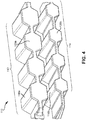
- FIG. 4 illustrates a perspective view of the crash elements structure 110, according to an embodiment of the present disclosure.
- a set of covers 120a are coupled laterally to the side of the set of apertures 119a
- a set of covers 120b are coupled laterally to the side of the set of apertures 119b.
- the set of covers 120 may be coupled to the set of apertures 119 by coupling to the edges of the upper shells 116 and the lower shells 118.
- One purpose of the set of covers 120 is to more evenly distribute an incoming force across the upper shells 116 and the lower shells 118 of the crash elements structure 110.
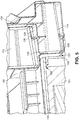
- FIG. 5 illustrates a perspective view
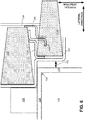
- FIG. 6 illustrates a front view of the vehicle battery 102 and the crash elements structure 110, according to an embodiment of the present disclosure.
- the upper structure 112 and the lower structure 114 have a trapezoidal shape that widens on the sides closer to the vehicle battery 102.
- the upper structure 112 may be laterally offset from the lower structure 114 from anywhere between 0% to 100%, 0% corresponding to the upper structure 112 being completely vertically above the lower structure 114 and 100% corresponding to all of the upper structure 112 being closer laterally to the vehicle battery 102 than any part of the lower structure 114.
- the upper structure 112 is approximately 30% laterally offset from the lower structure 114.
- the upper structure 112 is approximately 50% laterally offset from the lower structure 114.
- the crash elements structure 110 has a desired performance in a range of approximately 20%-60%.
- the crash elements structure 110 includes a "W" structure 122 that interfaces between the vehicle battery 102, the upper structure 112, and the lower structure 114.
- One purpose of the "W" structure 122 is to channel the energy received by the upper structure 112 and the lower structure 114 away from the vehicle battery 102 and toward a support structure 130 positioned above the vehicle battery 102.
- the support structure 130 may be coupled vertically above the battery top surface 104 and laterally to the side of the "W" structure 122 as shown in FIGs. 5 and 6 .
- the support structure 130 is ideally a component with a large energy absorption capacity.
- the support structure 130 may be coupled with additional components within the electric vehicle 100, such as the vehicle's body structure, so that energy is channeled away from the electric battery 102.
- the "W" structure 122 includes at least four sides.
- a first side of the “W” structure 122 may be substantially vertical and may couple laterally to the side of the upper structure 112 and laterally to the side of the support structure 130.
- a second side of the “W” structure 122 may be substantially horizontal and may couple vertically below the upper structure 112 and vertically above the battery top surface 104.
- a third side of the "W” structure 122 may be substantially vertical and may couple laterally to the side of the lower structure 114 and laterally to the side of the battery side surface 106.
- a fourth side of the "W” structure 122 may be substantially horizontal and may couple vertically below the lower structure 114.
- the first, second, third, and fourth sides of the "W” structure 122 may be planar and may form 90 degree angles with respect to each other.
- a gap 132 is positioned between the third side of the "W" structure 122 and the battery side surface 106.
- the gap 132 may be an air gap or may be filled with material as long as the filled material is weaker than the material of the "W" structure 122, i.e., the material of the gap 132 is collapsible at a lower force than the material of the "W" structure 122.
- the gap 132 may be 1 mm, 2 mm, 5 mm, 10 mm, and the like.
- One purpose of the gap 132 is to allow the "W" structure 122 to channel energy away from the vehicle battery 102 and toward the support structure 130. Simulation results (shown in FIG. 7 ) demonstrate that the crash elements structure 110 has an improved performance when the gap 132 is 5 mm.
- the crash elements structure 110 may include a first "S" structure 124, a second "S” structure 126, and a third "S" structure 128 for channeling energy away from the vehicle battery 102.
- the first "S” structure 124 may couple laterally to the side of the "W" structure122, laterally to the side of the lower structure 114, vertically above the lower structure 114, vertically below the upper structure 112, and laterally to the side of the second "S" structure 126.
- the second "S” structure 126 may couple laterally to the side of the first "S” structure 124, vertically above the lower structure 114, vertically below the upper structure 112, and laterally to the side of the third "S” structure 128.
- the third "S” structure 128 may couple laterally to the side of the second "S” structure 126, vertically above the lower structure 114, laterally to the side of the upper structure 112, and laterally to the side of a vehicle side 134.
- the second "S" structure 126 and the third “S” structure 128 may couple vertically above a concave portion of the upper shell 116b of the lower structure 114. This is illustrated in FIG. 6 by the overlapped portions of the second "S” structure 126 with the lower structure 114 and of the third "S” structure 128 with the lower structure 114.
- the first "S" structure 124 and the second “S” structure 126 may couple vertically below a convex portion of the lower shell 118a of the upper structure 112.
- the “S" structures provide several benefits to the functionality of the crash elements structure 110.
- the "S" structures may provide lateral containment of the upper structure 112 (between the "W” structure 122 and the third "S” structure 128) which reduces the amount of torque applied to the "W” structure in the event of a collision and instead provides a more linear transfer of energy to the support structure 130.
- the "S” structures redistribute energy from the lower structure 114 to the upper structure 112 by "grappling" the upper structure 112 via the third "S" structure 128.
- the "S" structures may be made from a more durable material than the upper structure 112 and the lower structure 114, such as steel or aluminum, which may cause an impact force applied to the vehicle side 134 to initially bypass the upper structure 112 and travel through the "S" structures and the "W” structure 122 to the support structure 130. Initially bypassing the upper structure 112 may be beneficial because the support structure 130 may have superior energy absorption properties.
- FIG. 7 illustrates simulation results for the electric vehicle 100 with the crash elements structure 110, according to an embodiment of the present disclosure.
- the simulation results show the incremental distance traveled by a pole into the electric vehicle 100 during a side impact.
- the crash elements structure 110 was modeled using 1 mm and 5 mm for the gap 132. The lesser amount of pole intrusion using a 5 mm gap indicates that the crash elements structure 110 has an improved performance when the gap 132 is 5 mm.
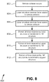
- FIG. 8 illustrates a method 800 for receiving an impact force related to a vehicle collision, according to an embodiment of the present disclosure.
- a vehicle collision occurs.
- the collision may be a head-on (front), side, or angled impact, or an impact from some other direction.
- the lower structure 114 receives a first force related to the impact force.
- the upper structure 112 receives a second force related to the impact force.
- a first portion of the first force received by the lower structure 114 is transferred to the "W" structure 122.
- a second portion of the second force received by the upper structure 112 is transferred to the "W" structure 122.
- a third portion of the force received by the "W" structure 122 is transferred to the support structure 130.
- configurations may be described as a process which is depicted as a flow diagram or block diagram. Although each may describe the operations as a sequential process, many of the operations can be performed in parallel or concurrently. In addition, the order of the operations may be rearranged. A process may have additional steps not included in the figure.
- examples of the methods may be implemented by hardware, software, firmware, middleware, microcode, hardware description languages, or any combination thereof
- the program code or code segments to perform the necessary tasks may be stored in a non-transitory computer-readable medium such as a storage medium. Processors may perform the described tasks.
Landscapes
- Engineering & Computer Science (AREA)
- Chemical & Material Sciences (AREA)
- General Chemical & Material Sciences (AREA)
- Electrochemistry (AREA)
- Chemical Kinetics & Catalysis (AREA)
- Mechanical Engineering (AREA)
- Transportation (AREA)
- Life Sciences & Earth Sciences (AREA)
- Power Engineering (AREA)
- Sustainable Energy (AREA)
- Sustainable Development (AREA)
- Aviation & Aerospace Engineering (AREA)
- Combustion & Propulsion (AREA)
- Body Structure For Vehicles (AREA)
- Arrangement Or Mounting Of Propulsion Units For Vehicles (AREA)
Applications Claiming Priority (2)
| Application Number | Priority Date | Filing Date | Title |
|---|---|---|---|
| US201662384298P | 2016-09-07 | 2016-09-07 | |
| US15/690,854 US10044006B2 (en) | 2016-09-07 | 2017-08-30 | Offset vehicle crash elements |
Publications (2)
| Publication Number | Publication Date |
|---|---|
| EP3293076A2 true EP3293076A2 (fr) | 2018-03-14 |
| EP3293076A3 EP3293076A3 (fr) | 2018-03-28 |
Family
ID=59811181
Family Applications (1)
| Application Number | Title | Priority Date | Filing Date |
|---|---|---|---|
| EP17189806.7A Withdrawn EP3293076A3 (fr) | 2016-09-07 | 2017-09-07 | Éléments décalés de collision de véhicule |
Country Status (3)
| Country | Link |
|---|---|
| US (3) | US10044006B2 (fr) |
| EP (1) | EP3293076A3 (fr) |
| CN (2) | CN107791816A (fr) |
Cited By (1)
| Publication number | Priority date | Publication date | Assignee | Title |
|---|---|---|---|---|
| WO2025144368A1 (fr) * | 2023-12-30 | 2025-07-03 | Siro Silk Road Temiz Enerji Depolama Teknolojileri Sanayi Ve Ticaret Anonim Sirketi | Véhicule comprenant une couche d'amortissement d'impact |
Families Citing this family (18)
| Publication number | Priority date | Publication date | Assignee | Title |
|---|---|---|---|---|
| US10632857B2 (en) | 2016-08-17 | 2020-04-28 | Shape Corp. | Battery support and protection structure for a vehicle |
| US10044006B2 (en) | 2016-09-07 | 2018-08-07 | Thunder Power New Energy Vehicle Development Company Limited | Offset vehicle crash elements |
| CN110383526A (zh) | 2017-01-04 | 2019-10-25 | 形状集团 | 节点模块化的车辆电池托盘结构 |
| WO2018213383A1 (fr) | 2017-05-16 | 2018-11-22 | Shape Corp. | Support de batterie de véhicule à 'éléments de retenue et de support de batterie intégrés |
| US10483510B2 (en) | 2017-05-16 | 2019-11-19 | Shape Corp. | Polarized battery tray for a vehicle |
| US10886513B2 (en) | 2017-05-16 | 2021-01-05 | Shape Corp. | Vehicle battery tray having tub-based integration |
| CN111108015A (zh) | 2017-09-13 | 2020-05-05 | 形状集团 | 具有管状外围壁的车辆电池托盘 |
| US12347879B2 (en) | 2017-09-13 | 2025-07-01 | Shape Corp. | Vehicle battery tray with tubular peripheral wall |
| WO2019071013A1 (fr) | 2017-10-04 | 2019-04-11 | Shape Corp. | Ensemble fond de bac support de batterie pour véhicules électriques |
| EP3759761B1 (fr) | 2018-03-01 | 2026-04-08 | Shape Corp. | Système de refroidissement intégré à un bac de batterie de véhicule |
| US11688910B2 (en) | 2018-03-15 | 2023-06-27 | Shape Corp. | Vehicle battery tray having tub-based component |
| DE102018120268A1 (de) * | 2018-08-21 | 2020-02-27 | Bmw Ag | Batteriekasten mit Verstärkungselement |
| HUE071435T2 (hu) * | 2018-10-09 | 2025-09-28 | Outokumpu Oy | Eljárás akkumulátorfoglalat ütközõkeretének gyártására akkumulátoros elektromos jármûvek számára |
| EP3709387A1 (fr) * | 2019-03-11 | 2020-09-16 | voestalpine Metal Forming GmbH | Boîtier de batterie pour une batterie de traction |
| US11539104B2 (en) | 2020-04-20 | 2022-12-27 | Toyota Motor Engineering & Manufacturing North America, Inc. | Battery pillar protector |
| US11996576B2 (en) * | 2020-07-03 | 2024-05-28 | Teijin Automotive Technologies, Inc. | Impact resistant frame of battery containment system |
| EP4253114B1 (fr) * | 2020-12-08 | 2026-01-28 | Nippon Steel Corporation | Boîtier de batterie automobile et son procédé de fabrication |
| US11876239B2 (en) * | 2021-11-23 | 2024-01-16 | Polestar Performance Ab | Directionally controlled failure of electric vehicle battery tray |
Family Cites Families (19)
| Publication number | Priority date | Publication date | Assignee | Title |
|---|---|---|---|---|
| US2728479A (en) * | 1951-02-09 | 1955-12-27 | Union Bag & Paper Corp | Honeycomb pad |
| US4227593A (en) * | 1976-10-04 | 1980-10-14 | H. H. Robertson Company | Kinetic energy absorbing pad |
| US4566237A (en) * | 1983-04-08 | 1986-01-28 | Goodyear Aerospace Corporation | Armored panel |
| US5175041A (en) * | 1991-01-28 | 1992-12-29 | Innovative Enterprises, Inc. | Corner and edge protector for packaging |
| US6372322B1 (en) * | 1998-05-28 | 2002-04-16 | Pactiv Corporation | Shaped honeycomb structures and method and apparatus for making shaped honeycomb structures |
| EP1065108B1 (fr) * | 1999-06-28 | 2004-04-21 | Mazda Motor Corporation | Structure d'une partie avant de caisse d'un véhicule automobile |
| US7806448B2 (en) * | 2008-11-04 | 2010-10-05 | Sabic Innovative Plastics Ip B.V. | Vehicle bumper system with energy absorber |
| DE112009004806B4 (de) * | 2009-05-28 | 2018-03-22 | Toyota Jidosha Kabushiki Kaisha | Brennstoffzellensystem und -fahrzeug |
| DE102010024320B4 (de) | 2010-06-18 | 2020-11-26 | Audi Ag | Vorrichtung zum Halten einer Batterie in einer Fahrzeugkarosserie |
| KR20120044853A (ko) * | 2010-10-28 | 2012-05-08 | 현대자동차주식회사 | 플라스틱 복합재를 이용한 전기자동차용 배터리팩 케이스 어셈블리 |
| US8336933B2 (en) * | 2010-11-04 | 2012-12-25 | Sabic Innovative Plastics Ip B.V. | Energy absorbing device and methods of making and using the same |
| DE102011102412B4 (de) | 2011-05-25 | 2023-06-29 | Volkswagen Aktiengesellschaft | Anordnung einer Traktionsbatterie in einem Fahrzeug |
| DE102013102502B4 (de) | 2013-03-13 | 2023-06-29 | Dr. Ing. H.C. F. Porsche Aktiengesellschaft | Kraftfahrzeug mit einem Schutzprofil |
| DE102014107388A1 (de) | 2014-05-26 | 2015-11-26 | Dr. Ing. H.C. F. Porsche Aktiengesellschaft | Unterbodeneinheit für ein Kraftfahrzeug |
| US9868361B2 (en) * | 2014-12-11 | 2018-01-16 | Ford Global Technologies, Llc | Battery impact absorbing system |
| US9656571B2 (en) | 2015-02-11 | 2017-05-23 | Ford Global Technologies, Llc | Battery enclosure having T-shaped guides on the outer surface for stiffeners and impact absorbing elements |
| US10439183B2 (en) * | 2015-02-11 | 2019-10-08 | Ford Global Technologies, Llc | Impact absorbing elements attached to the outer surface of a battery enclosure |
| US10336373B2 (en) * | 2016-09-07 | 2019-07-02 | Thunder Power New Energy Vehicle Development Company Limited | Lateral energy absorption system |
| US10044006B2 (en) | 2016-09-07 | 2018-08-07 | Thunder Power New Energy Vehicle Development Company Limited | Offset vehicle crash elements |
-
2017
- 2017-08-30 US US15/690,854 patent/US10044006B2/en active Active
- 2017-09-07 CN CN201710801723.5A patent/CN107791816A/zh active Pending
- 2017-09-07 EP EP17189806.7A patent/EP3293076A3/fr not_active Withdrawn
- 2017-09-07 CN CN201721144611.9U patent/CN207441781U/zh not_active Expired - Fee Related
- 2017-12-12 US US15/838,861 patent/US10044007B2/en active Active
-
2018
- 2018-07-13 US US16/034,371 patent/US10700313B2/en not_active Expired - Fee Related
Non-Patent Citations (1)
| Title |
|---|
| None |
Cited By (1)
| Publication number | Priority date | Publication date | Assignee | Title |
|---|---|---|---|---|
| WO2025144368A1 (fr) * | 2023-12-30 | 2025-07-03 | Siro Silk Road Temiz Enerji Depolama Teknolojileri Sanayi Ve Ticaret Anonim Sirketi | Véhicule comprenant une couche d'amortissement d'impact |
Also Published As
| Publication number | Publication date |
|---|---|
| US20180069205A1 (en) | 2018-03-08 |
| US10700313B2 (en) | 2020-06-30 |
| EP3293076A3 (fr) | 2018-03-28 |
| US10044007B2 (en) | 2018-08-07 |
| US20180323409A1 (en) | 2018-11-08 |
| CN207441781U (zh) | 2018-06-01 |
| US20180102515A1 (en) | 2018-04-12 |
| US10044006B2 (en) | 2018-08-07 |
| CN107791816A (zh) | 2018-03-13 |
Similar Documents
| Publication | Publication Date | Title |
|---|---|---|
| US10700313B2 (en) | Offset vehicle crash elements | |
| US10745052B2 (en) | Longitudinal crash beam receiver | |
| US9994257B2 (en) | Specific ribs in longitudinal crash beam | |
| US9981698B2 (en) | Vehicle tunnel floor structure | |
| US9643660B2 (en) | Bumper assembly for an undercarriage mounted battery pack | |
| US9988095B2 (en) | Vehicle A-pillar rib configuration | |
| US20110139534A1 (en) | Motor vehicle and body floor structure for a motor vehicle | |
| US11130525B2 (en) | Rear crash safety profile | |
| CN204323019U (zh) | 一种纯电动汽车的前舱结构 | |
| US20180065684A1 (en) | Front wall | |
| US10661832B2 (en) | Angle and geometry of the front cross member | |
| US10703418B2 (en) | Automobile front upper body stablizer | |
| CN221947294U (zh) | 一种高结构强度的电池箱 | |
| CN109204526B (zh) | 车身结构及车辆 | |
| KR102682602B1 (ko) | 배터리 탑재공간을 확장시킨 전기차량용 배터리 케이스 | |
| CN205075639U (zh) | 一种提高乘用车耐撞性能的前置结构 | |
| EP3293089A1 (fr) | Tour de choc arrière |
Legal Events
| Date | Code | Title | Description |
|---|---|---|---|
| PUAI | Public reference made under article 153(3) epc to a published international application that has entered the european phase |
Free format text: ORIGINAL CODE: 0009012 |
|
| STAA | Information on the status of an ep patent application or granted ep patent |
Free format text: STATUS: THE APPLICATION HAS BEEN PUBLISHED |
|
| PUAL | Search report despatched |
Free format text: ORIGINAL CODE: 0009013 |
|
| AK | Designated contracting states |
Kind code of ref document: A2 Designated state(s): AL AT BE BG CH CY CZ DE DK EE ES FI FR GB GR HR HU IE IS IT LI LT LU LV MC MK MT NL NO PL PT RO RS SE SI SK SM TR |
|
| AX | Request for extension of the european patent |
Extension state: BA ME |
|
| AK | Designated contracting states |
Kind code of ref document: A3 Designated state(s): AL AT BE BG CH CY CZ DE DK EE ES FI FR GB GR HR HU IE IS IT LI LT LU LV MC MK MT NL NO PL PT RO RS SE SI SK SM TR |
|
| AX | Request for extension of the european patent |
Extension state: BA ME |
|
| RIC1 | Information provided on ipc code assigned before grant |
Ipc: B62D 21/02 20060101AFI20180220BHEP Ipc: B62D 25/20 20060101ALI20180220BHEP Ipc: H01M 2/10 20060101ALI20180220BHEP Ipc: B62D 29/00 20060101ALI20180220BHEP |
|
| STAA | Information on the status of an ep patent application or granted ep patent |
Free format text: STATUS: REQUEST FOR EXAMINATION WAS MADE |
|
| 17P | Request for examination filed |
Effective date: 20180927 |
|
| RBV | Designated contracting states (corrected) |
Designated state(s): AL AT BE BG CH CY CZ DE DK EE ES FI FR GB GR HR HU IE IS IT LI LT LU LV MC MK MT NL NO PL PT RO RS SE SI SK SM TR |
|
| GRAP | Despatch of communication of intention to grant a patent |
Free format text: ORIGINAL CODE: EPIDOSNIGR1 |
|
| STAA | Information on the status of an ep patent application or granted ep patent |
Free format text: STATUS: GRANT OF PATENT IS INTENDED |
|
| INTG | Intention to grant announced |
Effective date: 20181120 |
|
| GRAJ | Information related to disapproval of communication of intention to grant by the applicant or resumption of examination proceedings by the epo deleted |
Free format text: ORIGINAL CODE: EPIDOSDIGR1 |
|
| STAA | Information on the status of an ep patent application or granted ep patent |
Free format text: STATUS: REQUEST FOR EXAMINATION WAS MADE |
|
| GRAP | Despatch of communication of intention to grant a patent |
Free format text: ORIGINAL CODE: EPIDOSNIGR1 |
|
| STAA | Information on the status of an ep patent application or granted ep patent |
Free format text: STATUS: GRANT OF PATENT IS INTENDED |
|
| INTC | Intention to grant announced (deleted) | ||
| INTG | Intention to grant announced |
Effective date: 20190418 |
|
| STAA | Information on the status of an ep patent application or granted ep patent |
Free format text: STATUS: THE APPLICATION IS DEEMED TO BE WITHDRAWN |
|
| 18D | Application deemed to be withdrawn |
Effective date: 20190829 |