EP3293335A1 - Entkupplung des steuerarms eines klappladens - Google Patents
Entkupplung des steuerarms eines klappladens Download PDFInfo
- Publication number
- EP3293335A1 EP3293335A1 EP17189335.7A EP17189335A EP3293335A1 EP 3293335 A1 EP3293335 A1 EP 3293335A1 EP 17189335 A EP17189335 A EP 17189335A EP 3293335 A1 EP3293335 A1 EP 3293335A1
- Authority
- EP
- European Patent Office
- Prior art keywords
- arm
- lever
- arms
- motor
- motorized
- Prior art date
- Legal status (The legal status is an assumption and is not a legal conclusion. Google has not performed a legal analysis and makes no representation as to the accuracy of the status listed.)
- Granted
Links
Images


Classifications
-
- E—FIXED CONSTRUCTIONS
- E05—LOCKS; KEYS; WINDOW OR DOOR FITTINGS; SAFES
- E05F—DEVICES FOR MOVING WINGS INTO OPEN OR CLOSED POSITION; CHECKS FOR WINGS; WING FITTINGS NOT OTHERWISE PROVIDED FOR, CONCERNED WITH THE FUNCTIONING OF THE WING
- E05F15/00—Power-operated mechanisms for wings
- E05F15/60—Power-operated mechanisms for wings using electrical actuators
- E05F15/603—Power-operated mechanisms for wings using electrical actuators using rotary electromotors
- E05F15/611—Power-operated mechanisms for wings using electrical actuators using rotary electromotors for swinging wings
- E05F15/614—Power-operated mechanisms for wings using electrical actuators using rotary electromotors for swinging wings operated by meshing gear wheels, one of which being mounted at the wing pivot axis; operated by a motor acting directly on the wing pivot axis
-
- E—FIXED CONSTRUCTIONS
- E05—LOCKS; KEYS; WINDOW OR DOOR FITTINGS; SAFES
- E05F—DEVICES FOR MOVING WINGS INTO OPEN OR CLOSED POSITION; CHECKS FOR WINGS; WING FITTINGS NOT OTHERWISE PROVIDED FOR, CONCERNED WITH THE FUNCTIONING OF THE WING
- E05F15/00—Power-operated mechanisms for wings
- E05F15/60—Power-operated mechanisms for wings using electrical actuators
- E05F15/603—Power-operated mechanisms for wings using electrical actuators using rotary electromotors
- E05F15/611—Power-operated mechanisms for wings using electrical actuators using rotary electromotors for swinging wings
- E05F15/63—Power-operated mechanisms for wings using electrical actuators using rotary electromotors for swinging wings operated by swinging arms
-
- E—FIXED CONSTRUCTIONS
- E05—LOCKS; KEYS; WINDOW OR DOOR FITTINGS; SAFES
- E05Y—INDEXING SCHEME ASSOCIATED WITH SUBCLASSES E05D AND E05F, RELATING TO CONSTRUCTION ELEMENTS, ELECTRIC CONTROL, POWER SUPPLY, POWER SIGNAL OR TRANSMISSION, USER INTERFACES, MOUNTING OR COUPLING, DETAILS, ACCESSORIES, AUXILIARY OPERATIONS NOT OTHERWISE PROVIDED FOR, APPLICATION THEREOF
- E05Y2201/00—Constructional elements; Accessories therefor
- E05Y2201/20—Brakes; Disengaging means; Holders; Stops; Valves; Accessories therefor
- E05Y2201/214—Disengaging means
-
- E—FIXED CONSTRUCTIONS
- E05—LOCKS; KEYS; WINDOW OR DOOR FITTINGS; SAFES
- E05Y—INDEXING SCHEME ASSOCIATED WITH SUBCLASSES E05D AND E05F, RELATING TO CONSTRUCTION ELEMENTS, ELECTRIC CONTROL, POWER SUPPLY, POWER SIGNAL OR TRANSMISSION, USER INTERFACES, MOUNTING OR COUPLING, DETAILS, ACCESSORIES, AUXILIARY OPERATIONS NOT OTHERWISE PROVIDED FOR, APPLICATION THEREOF
- E05Y2400/00—Electronic control; Electrical power; Power supply; Power or signal transmission; User interfaces
- E05Y2400/10—Electronic control
- E05Y2400/30—Electronic control of motors
- E05Y2400/3013—Electronic control of motors during manual wing operation
-
- E—FIXED CONSTRUCTIONS
- E05—LOCKS; KEYS; WINDOW OR DOOR FITTINGS; SAFES
- E05Y—INDEXING SCHEME ASSOCIATED WITH SUBCLASSES E05D AND E05F, RELATING TO CONSTRUCTION ELEMENTS, ELECTRIC CONTROL, POWER SUPPLY, POWER SIGNAL OR TRANSMISSION, USER INTERFACES, MOUNTING OR COUPLING, DETAILS, ACCESSORIES, AUXILIARY OPERATIONS NOT OTHERWISE PROVIDED FOR, APPLICATION THEREOF
- E05Y2900/00—Application of doors, windows, wings or fittings thereof
- E05Y2900/10—Application of doors, windows, wings or fittings thereof for buildings or parts thereof
- E05Y2900/13—Type of wing
- E05Y2900/146—Shutters
Definitions
- the present invention generally relates to shutter devices of an opening in a wall of a building, opening generally housing a door or window. More particularly, the invention may relate to the shutters which shutter these openings, mounted for this purpose in most cases alone or in pairs.
- shutters work in the manner of screens capable of closing more or less completely the openings for purposes such as occultation of daylight, or thermal barrier in one direction or the other, or sound barrier .
- thermal insulation the closing of the leaves is often used to preserve some coolness inside the building in summer, but it may also be an additional way to keep the heat in the winter or to prevent the cold outside to enter.
- the invention relates only to the motorized swing shutters, whose movement on opening or closing is dependent on drive means, in general electric motors, themselves controlled via electronic control cards which manage in particular the control devices such as switches or remote controls.
- the flaps must indeed be opened or closed in a predetermined order which depends on their role: one, provided with a cover blade forming a cover, being the covering flap while the other, which is lacking, is the covered flywheel.
- a closing phase the covering wing must arrive in closed abutment after the covered wing, and is therefore driven after the other, with an offset or at a lower speed at less in a predetermined part of the course.
- an opening phase it is the opposite, the covering flap is driven first so that the covered wing can in turn move without obstacle.
- the simultaneous control of two leaves may require the implementation and the management of a communication between them in particular to manage the priority of movement, but also to respond to all kinds of unforeseen situations that may inhibit or hamper normal operation fenders.
- These may be obstacles that prevent one of the components from moving, and may eventually damage the system, or a weather event generating potentially destructive stresses (winds of various powers or orientations), these events requiring on the part of the electronic control system, or on the part of the users, a suitable answer.
- the present invention provides several clutch release / clutch solutions and motorized drive means, simple to implement with elegant mechanical configurations and easy to manufacture.
- a lever with a flexible blade that is to say with a certain elasticity, is provided to cooperate with the arms to immobilize them or, on the contrary, to leave them independent.
- the implementation of the securing means depends in practice on the position of this movable lever, which however does not immobilize the arms only in a single position.
- the lever is for example rotatably mounted in contact with a first arm, and has at least one free end provided with positioning and locking surfaces of the second arm in the alignment of the first arm when the lever is aligned with the two arms.
- the lever comprises a stud having a barrel surmounted by a head protruding on both sides of the barrel at least in one direction.
- Each arm has an orifice having on the one hand a central circular portion of diameter greater than the largest dimension of the barrel, allowing a tight fit of the one in the other, and less than the largest dimension of the head and on the other hand diametrically opposite lateral notches made along the axis of the arm.
- These orifices of each arm are coaxial when the arms are superimposed and axes oriented parallel, the dimensions of the notches of at least the orifice of the distal arm of the lever allowing the passage of the head of the stud.
- the partially corresponding shape of the orifices and the head of the stud allows the latter to cross one or both arms when the blade is in a certain position relative to the arms (for example perpendicular to them) and then, when the head has passed through the orifices, the blade is turned so as to lock the two arms coaxially.
- the locking occurs due to the tight fit that is implemented in this position.
- the head of the stud then rests in contact with the distal surface of the arm which is not in contact with the lever.
- said head may be dimensioned such that it is retained in the orifice of the arm in contact with which the lever moves.
- a solution in which no retention is put in place therefore comprising a completely removable lever that is inserted successively into the two aligned orifices when the arms are coaxial, then that one turns to realize the joining of the arms, fixing at the same time the lever to the whole.
- the barrel of the stud may be oblong, and arranged transversely to the flexible blade of the lever, the head then protruding from the barrel at least in the long length of the oblong.
- the flexible blade lever can be rotatably connected to the drive arm and have an end shape configured and dimensioned to fit into an axial cut in the free end of the motor arm and the rotated during a rotational movement of the lever to align with the drive arm.
- the transverse dimensions and the respective configurations of the cutout and the end shape then make it possible to align the two arms when the lever is in the axis of the drive arm, position in which locking means in position equipping this last and the lever are automatically activated.
- the means for locking the lever relative to the drive arm consist of a boss protruding from one and a recess of corresponding shape formed in the other, the boss clipping into the recess when alignment is achieved, the boss or recess being disposed adjacent a free end of the flexible blade.
- the end shape of the lever can consist of a hook whose end is perpendicular to the flexible blade and rests on the surface of the arm.
- the remainder of the hook may consist, for example, in an inclined section and a section of parallel shape to the main flat part of the blade, these two sections connecting the latter to the end.
- a U-shaped cutout of transverse dimension greater than the width of the end is also made in the free end of the motor arm.
- the lever can be rotatably mounted according to the axis of rotation of the motorized shaft, of the same width as the drive arms and motor in the vicinity of its free end and endowed with on either side of said end flaps perpendicular to the flexible blade flanking and laterally locking the arms.
- the locking of the two arms is effected when the blade and said arms are superimposed aligned, the only position allowing the edges of the blade to overflow the lateral fields of the arms.
- the lever is provided, at a free end, with a gripping tongue oriented at an angle away from the face of the arm with which the lever is in contact, so as to facilitate the manipulation of the blade between its positions respectively inactive and active locking arm respectively motor and drive.
- the control arm of a leaf flap comprises a driving arm (1) and a motor arm (2) arranged at one end of a motorized shaft (3), and a locking lever (4) under the shape of a blade flexible.
- the motor arm (2) is rotatably connected to the shaft (3), while the drive arm (1) is mounted idle.
- the locking lever (4) is rotatable relative to the two arms (1, 2) via an end stud (5) consisting of a shaft (6), in this case oblong, surmounted by a head (7) which protrudes in the direction of the major axis of the oblong section.
- the other end of the flexible blade of the lever (4) comprises a gripping tab (8) for manipulating the lever (4).
- This stud (5) which appears more clearly in figure 2 , organizes the rotation and locking of the lever (4) relative to the arms (1, 2), via orifices (11, 21) formed respectively in the drive arm (1) and motor (2).
- These orifices (11, 21), of identical or almost identical shape, comprise a circular central opening and two aligned oval notches increasing the diametrical dimension of the orifice in the direction of their extension. In the configuration shown, said notches are directed along the axis of the arms (1, 2), and they are shaped and sized to let the head (7) of the lever (4).
- the greatest length of the orifice (11), at the level of said notches, may be a little smaller than that of the head (7) in the arm (1), so that the lever (4) can be maintained in this position. drive arm (1) even in the unlocked position, as illustrated in figure 1 .
- the lever (4) can be detachable if the condition of length above is not respected, but on the contrary the greatest length of the orifice (11) at the notches is always greater than the long head (7), for both arms (1, 2).
- the same greater length relative to the orifice (21) is provided slightly larger than that of the head (7), so as not to impede the mobility of the head (7) in the orifice (21). in the direction of the B axis (see figure 3 ).
- the diameter of the circular central opening is a little greater than the large length of the barrel (6), with a tight fit of the one in the other, so as to allow the firm guidance of the rotation of one in the other, then the locking in aligned position.
- Said barrel (6) also has a height under the head (7) of the same order, very slightly greater in fact, to the double thickness of the arms (1, 2) superimposed.
- the operation is then as follows: the stud (5) inserted into the orifice (11) can not cross the orifice (21) unless on the one hand the head (7) is aligned with the ears, that is, that is, if the lever (4) is positioned perpendicularly to the drive arm (1) and, on the other hand, the two arms (1, 2) are aligned so that the orifices (11, 21) become coaxial.
- the stud (5) can be moved through the orifice (21) until the head protrudes from the surface (22) of the arm (2), releasing said head (7) and consequently the rotation of the lever (4). It is then sufficient to rotate said lever (4) to align with the two arms (1, 2) already in parallel position.
- a means for holding or locking in aligned position may be provided on the lever (4), for example a boss cooperating with a recess of corresponding dimensions made in the drive arm (1), the boss and the recess being localized such that they cooperate by clipping made possible by the elastic blade when the lever (4) is aligned with the arms (1, 2).
- the lever (4) and the arms (1, 2) cooperate with each other in this configuration by means of the end surfaces of the barrel (6) and the inner surfaces of the orifices (11, 21). in their sectors perpendicular to the notches, whose tight fit allows blocking.
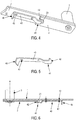
- FIGS. 4 to 6 represent an alternative design of the invention, in which the changes with respect to the configuration of Figures 1 to 3 mainly concern the lever (40) rotatably mounted for example by riveting with respect to the arm (1) but this time on the same side as the motor arm (2).
- a free end of the lever (40) is provided with a hook (41) whose free end (42) is oriented substantially perpendicular to the face (12) of the arm (1) and slides on or at least is very close of this face (12).
- the end (42) cooperates with a cutout (23) of the motor arm (2), for example a U-shaped cutout, which opens at the free end of said motor arm (2), the respective shapes and dimensions of the cutout (23). ) and the end (42) allowing a rotary drive of the motor arm (2) by the lever (40).
- the co-operating surfaces to achieve the positioning and the aligned locking of the arms (1, 2) are this time of two kinds: the outer lateral surfaces of the end (42) and the internal surfaces of the U-shaped cutout (23) for aligned positioning. , and the outer and inner surfaces respectively the boss (43) and the recess (23) for the aligned locking.
- FIG. 7 to 9 Yet another variant of the invention appears in the Figures 7 to 9 .
- the lever (50) is rotatable relative to the main axis of rotation A of the motorized shaft (3), as in the first configuration.
- This lever (50) - whose flexible blade is of the same width as the arms (1, 2) - comprises, in the vicinity of the free end of the flexible blade (50), two side flaps (51) parallel to each other and perpendicular to the flexible blade which border and enclose the side edges of the two arms (1, 2) when aligned, and block in this driving position of the flap.
- the elasticity of the blade is particularly important in this configuration, as shown in particular by the figure 8 it must be able to deform said blade to pass one of the side flaps (51) from one side to the other of the motor arm (2), in contact with the face (24) of the arm (2).
- the gripping tongue (58) is doubly useful in this configuration for the rotational drive as well as for bending the lever (50) for transverse crossing of the motor arm (2) by one of the flaps (51). Due to its elasticity, said blade returns to the rest position in contact with the opposite face of the motor arm (2).
- the internal surfaces of the flaps (51) and the surfaces of the side edges of the arms (1, 2) cooperate to achieve locking in the aligned and locked position of the respective motor (2) and drive (1) arms. .
Landscapes
- Operating, Guiding And Securing Of Roll- Type Closing Members (AREA)
- Lock And Its Accessories (AREA)
- Power-Operated Mechanisms For Wings (AREA)
- Air-Flow Control Members (AREA)
Priority Applications (1)
| Application Number | Priority Date | Filing Date | Title |
|---|---|---|---|
| PL17189335T PL3293335T3 (pl) | 2016-09-07 | 2017-09-05 | Napęd silnikowy dla co najmniej jednego skrzydła rolety |
Applications Claiming Priority (1)
| Application Number | Priority Date | Filing Date | Title |
|---|---|---|---|
| FR1658316A FR3055648B1 (fr) | 2016-09-07 | 2016-09-07 | Desaccouplement du bras de commande d'un volet battant. |
Publications (2)
| Publication Number | Publication Date |
|---|---|
| EP3293335A1 true EP3293335A1 (de) | 2018-03-14 |
| EP3293335B1 EP3293335B1 (de) | 2022-01-26 |
Family
ID=57860956
Family Applications (1)
| Application Number | Title | Priority Date | Filing Date |
|---|---|---|---|
| EP17189335.7A Active EP3293335B1 (de) | 2016-09-07 | 2017-09-05 | Motorisierte antriebsvorrichtung für mindestens einen flügel |
Country Status (4)
| Country | Link |
|---|---|
| EP (1) | EP3293335B1 (de) |
| ES (1) | ES2907631T3 (de) |
| FR (1) | FR3055648B1 (de) |
| PL (1) | PL3293335T3 (de) |
Citations (3)
| Publication number | Priority date | Publication date | Assignee | Title |
|---|---|---|---|---|
| US4970826A (en) * | 1989-11-24 | 1990-11-20 | Door King, Inc. | Apparatus and method for opening and closing a gate |
| EP0965717A2 (de) * | 1998-06-19 | 1999-12-22 | Cardin Elettronica S.p.A. | Vorrichtung zum schnellen Lösen von Torflügeln |
| EP0969174A2 (de) * | 1998-05-29 | 2000-01-05 | Joseph Peter William Baker | Verbesserungen bezüglich Verschlusselementen |
-
2016
- 2016-09-07 FR FR1658316A patent/FR3055648B1/fr active Active
-
2017
- 2017-09-05 EP EP17189335.7A patent/EP3293335B1/de active Active
- 2017-09-05 PL PL17189335T patent/PL3293335T3/pl unknown
- 2017-09-05 ES ES17189335T patent/ES2907631T3/es active Active
Patent Citations (3)
| Publication number | Priority date | Publication date | Assignee | Title |
|---|---|---|---|---|
| US4970826A (en) * | 1989-11-24 | 1990-11-20 | Door King, Inc. | Apparatus and method for opening and closing a gate |
| EP0969174A2 (de) * | 1998-05-29 | 2000-01-05 | Joseph Peter William Baker | Verbesserungen bezüglich Verschlusselementen |
| EP0965717A2 (de) * | 1998-06-19 | 1999-12-22 | Cardin Elettronica S.p.A. | Vorrichtung zum schnellen Lösen von Torflügeln |
Also Published As
| Publication number | Publication date |
|---|---|
| FR3055648B1 (fr) | 2019-12-13 |
| FR3055648A1 (fr) | 2018-03-09 |
| ES2907631T3 (es) | 2022-04-25 |
| PL3293335T3 (pl) | 2022-03-28 |
| EP3293335B1 (de) | 2022-01-26 |
Similar Documents
| Publication | Publication Date | Title |
|---|---|---|
| EP2069184B1 (de) | Mechanismus zur bedienung von schaltpunkten | |
| EP3404176A1 (de) | Vorrichtung zum entriegeln eines türschlosses | |
| EP1493664B1 (de) | Verriegelungseinrichtung für die Verkleidung einer Triebwerkgondel | |
| EP0645511B1 (de) | Schloss für eine Kraftfahrzeugtür | |
| FR2802240A1 (fr) | Dispositif de fixation pour un arbre d'enroulement et mecanisme de manoeuvre d'une installation de fermeture ou de protection solaire comprenant un tel dispositif | |
| EP2045420B1 (de) | Griffsystem, insbesondere Treibstange, das zur Befestigung auf der Außenseite einer Tür bestimmt ist, wie etwa der Tür eines Kühllasters | |
| EP3293335B1 (de) | Motorisierte antriebsvorrichtung für mindestens einen flügel | |
| FR3066565A1 (fr) | Dispositif de liaison actionneur-levier pour dispositif d'obturation de face avant de vehicule automobile, et dispositif d'obturation de face avant associe | |
| EP1674647A2 (de) | Antriebsvorrichtung für Schliesssystem wie Laden, Tor usw. | |
| EP1528199A1 (de) | Vorrichtung für Mehrpunktverriegelung, insbesondere für eine Sektionaltor | |
| FR2508124A1 (fr) | Fourchette de commande pour butee de debrayage et son procede de montage | |
| EP2729647B1 (de) | Vorrichtung zur steuerung der mehrpunktverriegelung eines öffnungsflügels | |
| FR2567949A1 (fr) | Dispositif de commande de l'ouverture d'une serrure de portiere de vehicule automobile | |
| FR2861789A1 (fr) | Serrure anti-panique multipoint reversible | |
| FR2815069A1 (fr) | Dispositif de deverrouillage de volets a battants entraines mecaniquement | |
| EP1059409A1 (de) | Antriebsgetriebe für Schlossnuss | |
| EP3530851B1 (de) | Verriegelungssystem für eine brandschutztür mit seitlicher verschiebung | |
| EP1655445A2 (de) | Antrieb eines Belüftungssystems aus Schwenklamellen mit Notöffnung | |
| EP0241396B1 (de) | Automatischer Treibstangenverschluss mit Doppelaktion | |
| EP1355031A1 (de) | Verriegelungsvorrichtung für ein motorisiertes Tor | |
| EP1865224A1 (de) | System und Vorrichtung zur Übertragung einer Drehbewegung eines ersten Gegenstands um eine erste Achse auf einen zweiten Gegenstand um eine zweite Achse | |
| EP1026350A1 (de) | Türgriff für Kraftfahrzeug | |
| EP1059415A1 (de) | Gurtaufroller, Rolladen- oder Storebetätigungsmechanismus mit einem solchen Aufroller und Verfahren zur Herstellung eines solchen Aufrollers | |
| FR2881782A1 (fr) | Transmission mouvement et blocage pour battants de volets | |
| EP0833035A1 (de) | Arretierung für Rolladen, mit einer frei drehbaren Wickelwelle |
Legal Events
| Date | Code | Title | Description |
|---|---|---|---|
| PUAI | Public reference made under article 153(3) epc to a published international application that has entered the european phase |
Free format text: ORIGINAL CODE: 0009012 |
|
| STAA | Information on the status of an ep patent application or granted ep patent |
Free format text: STATUS: THE APPLICATION HAS BEEN PUBLISHED |
|
| AK | Designated contracting states |
Kind code of ref document: A1 Designated state(s): AL AT BE BG CH CY CZ DE DK EE ES FI FR GB GR HR HU IE IS IT LI LT LU LV MC MK MT NL NO PL PT RO RS SE SI SK SM TR |
|
| AX | Request for extension of the european patent |
Extension state: BA ME |
|
| STAA | Information on the status of an ep patent application or granted ep patent |
Free format text: STATUS: REQUEST FOR EXAMINATION WAS MADE |
|
| 17P | Request for examination filed |
Effective date: 20180716 |
|
| RBV | Designated contracting states (corrected) |
Designated state(s): AL AT BE BG CH CY CZ DE DK EE ES FI FR GB GR HR HU IE IS IT LI LT LU LV MC MK MT NL NO PL PT RO RS SE SI SK SM TR |
|
| STAA | Information on the status of an ep patent application or granted ep patent |
Free format text: STATUS: EXAMINATION IS IN PROGRESS |
|
| 17Q | First examination report despatched |
Effective date: 20200414 |
|
| RAP1 | Party data changed (applicant data changed or rights of an application transferred) |
Owner name: BUBENDORFF SA |
|
| RAP1 | Party data changed (applicant data changed or rights of an application transferred) |
Owner name: BHG |
|
| GRAP | Despatch of communication of intention to grant a patent |
Free format text: ORIGINAL CODE: EPIDOSNIGR1 |
|
| STAA | Information on the status of an ep patent application or granted ep patent |
Free format text: STATUS: GRANT OF PATENT IS INTENDED |
|
| INTG | Intention to grant announced |
Effective date: 20210701 |
|
| GRAJ | Information related to disapproval of communication of intention to grant by the applicant or resumption of examination proceedings by the epo deleted |
Free format text: ORIGINAL CODE: EPIDOSDIGR1 |
|
| STAA | Information on the status of an ep patent application or granted ep patent |
Free format text: STATUS: EXAMINATION IS IN PROGRESS |
|
| INTC | Intention to grant announced (deleted) | ||
| GRAP | Despatch of communication of intention to grant a patent |
Free format text: ORIGINAL CODE: EPIDOSNIGR1 |
|
| STAA | Information on the status of an ep patent application or granted ep patent |
Free format text: STATUS: GRANT OF PATENT IS INTENDED |
|
| INTG | Intention to grant announced |
Effective date: 20211027 |
|
| GRAS | Grant fee paid |
Free format text: ORIGINAL CODE: EPIDOSNIGR3 |
|
| GRAA | (expected) grant |
Free format text: ORIGINAL CODE: 0009210 |
|
| STAA | Information on the status of an ep patent application or granted ep patent |
Free format text: STATUS: THE PATENT HAS BEEN GRANTED |
|
| AK | Designated contracting states |
Kind code of ref document: B1 Designated state(s): AL AT BE BG CH CY CZ DE DK EE ES FI FR GB GR HR HU IE IS IT LI LT LU LV MC MK MT NL NO PL PT RO RS SE SI SK SM TR |
|
| REG | Reference to a national code |
Ref country code: GB Ref legal event code: FG4D Free format text: NOT ENGLISH |
|
| REG | Reference to a national code |
Ref country code: CH Ref legal event code: EP |
|
| REG | Reference to a national code |
Ref country code: AT Ref legal event code: REF Ref document number: 1465423 Country of ref document: AT Kind code of ref document: T Effective date: 20220215 |
|
| REG | Reference to a national code |
Ref country code: IE Ref legal event code: FG4D Free format text: LANGUAGE OF EP DOCUMENT: FRENCH |
|
| REG | Reference to a national code |
Ref country code: DE Ref legal event code: R096 Ref document number: 602017052696 Country of ref document: DE |
|
| REG | Reference to a national code |
Ref country code: ES Ref legal event code: FG2A Ref document number: 2907631 Country of ref document: ES Kind code of ref document: T3 Effective date: 20220425 |
|
| REG | Reference to a national code |
Ref country code: LT Ref legal event code: MG9D |
|
| REG | Reference to a national code |
Ref country code: NL Ref legal event code: MP Effective date: 20220126 |
|
| REG | Reference to a national code |
Ref country code: AT Ref legal event code: MK05 Ref document number: 1465423 Country of ref document: AT Kind code of ref document: T Effective date: 20220126 |
|
| PG25 | Lapsed in a contracting state [announced via postgrant information from national office to epo] |
Ref country code: NL Free format text: LAPSE BECAUSE OF FAILURE TO SUBMIT A TRANSLATION OF THE DESCRIPTION OR TO PAY THE FEE WITHIN THE PRESCRIBED TIME-LIMIT Effective date: 20220126 |
|
| PG25 | Lapsed in a contracting state [announced via postgrant information from national office to epo] |
Ref country code: SE Free format text: LAPSE BECAUSE OF FAILURE TO SUBMIT A TRANSLATION OF THE DESCRIPTION OR TO PAY THE FEE WITHIN THE PRESCRIBED TIME-LIMIT Effective date: 20220126 Ref country code: RS Free format text: LAPSE BECAUSE OF FAILURE TO SUBMIT A TRANSLATION OF THE DESCRIPTION OR TO PAY THE FEE WITHIN THE PRESCRIBED TIME-LIMIT Effective date: 20220126 Ref country code: PT Free format text: LAPSE BECAUSE OF FAILURE TO SUBMIT A TRANSLATION OF THE DESCRIPTION OR TO PAY THE FEE WITHIN THE PRESCRIBED TIME-LIMIT Effective date: 20220526 Ref country code: NO Free format text: LAPSE BECAUSE OF FAILURE TO SUBMIT A TRANSLATION OF THE DESCRIPTION OR TO PAY THE FEE WITHIN THE PRESCRIBED TIME-LIMIT Effective date: 20220426 Ref country code: LT Free format text: LAPSE BECAUSE OF FAILURE TO SUBMIT A TRANSLATION OF THE DESCRIPTION OR TO PAY THE FEE WITHIN THE PRESCRIBED TIME-LIMIT Effective date: 20220126 Ref country code: HR Free format text: LAPSE BECAUSE OF FAILURE TO SUBMIT A TRANSLATION OF THE DESCRIPTION OR TO PAY THE FEE WITHIN THE PRESCRIBED TIME-LIMIT Effective date: 20220126 Ref country code: BG Free format text: LAPSE BECAUSE OF FAILURE TO SUBMIT A TRANSLATION OF THE DESCRIPTION OR TO PAY THE FEE WITHIN THE PRESCRIBED TIME-LIMIT Effective date: 20220426 |
|
| PG25 | Lapsed in a contracting state [announced via postgrant information from national office to epo] |
Ref country code: LV Free format text: LAPSE BECAUSE OF FAILURE TO SUBMIT A TRANSLATION OF THE DESCRIPTION OR TO PAY THE FEE WITHIN THE PRESCRIBED TIME-LIMIT Effective date: 20220126 Ref country code: GR Free format text: LAPSE BECAUSE OF FAILURE TO SUBMIT A TRANSLATION OF THE DESCRIPTION OR TO PAY THE FEE WITHIN THE PRESCRIBED TIME-LIMIT Effective date: 20220427 Ref country code: FI Free format text: LAPSE BECAUSE OF FAILURE TO SUBMIT A TRANSLATION OF THE DESCRIPTION OR TO PAY THE FEE WITHIN THE PRESCRIBED TIME-LIMIT Effective date: 20220126 Ref country code: AT Free format text: LAPSE BECAUSE OF FAILURE TO SUBMIT A TRANSLATION OF THE DESCRIPTION OR TO PAY THE FEE WITHIN THE PRESCRIBED TIME-LIMIT Effective date: 20220126 |
|
| PG25 | Lapsed in a contracting state [announced via postgrant information from national office to epo] |
Ref country code: IS Free format text: LAPSE BECAUSE OF FAILURE TO SUBMIT A TRANSLATION OF THE DESCRIPTION OR TO PAY THE FEE WITHIN THE PRESCRIBED TIME-LIMIT Effective date: 20220526 |
|
| REG | Reference to a national code |
Ref country code: DE Ref legal event code: R097 Ref document number: 602017052696 Country of ref document: DE |
|
| PG25 | Lapsed in a contracting state [announced via postgrant information from national office to epo] |
Ref country code: SM Free format text: LAPSE BECAUSE OF FAILURE TO SUBMIT A TRANSLATION OF THE DESCRIPTION OR TO PAY THE FEE WITHIN THE PRESCRIBED TIME-LIMIT Effective date: 20220126 Ref country code: SK Free format text: LAPSE BECAUSE OF FAILURE TO SUBMIT A TRANSLATION OF THE DESCRIPTION OR TO PAY THE FEE WITHIN THE PRESCRIBED TIME-LIMIT Effective date: 20220126 Ref country code: RO Free format text: LAPSE BECAUSE OF FAILURE TO SUBMIT A TRANSLATION OF THE DESCRIPTION OR TO PAY THE FEE WITHIN THE PRESCRIBED TIME-LIMIT Effective date: 20220126 Ref country code: EE Free format text: LAPSE BECAUSE OF FAILURE TO SUBMIT A TRANSLATION OF THE DESCRIPTION OR TO PAY THE FEE WITHIN THE PRESCRIBED TIME-LIMIT Effective date: 20220126 Ref country code: DK Free format text: LAPSE BECAUSE OF FAILURE TO SUBMIT A TRANSLATION OF THE DESCRIPTION OR TO PAY THE FEE WITHIN THE PRESCRIBED TIME-LIMIT Effective date: 20220126 Ref country code: CZ Free format text: LAPSE BECAUSE OF FAILURE TO SUBMIT A TRANSLATION OF THE DESCRIPTION OR TO PAY THE FEE WITHIN THE PRESCRIBED TIME-LIMIT Effective date: 20220126 |
|
| PG25 | Lapsed in a contracting state [announced via postgrant information from national office to epo] |
Ref country code: AL Free format text: LAPSE BECAUSE OF FAILURE TO SUBMIT A TRANSLATION OF THE DESCRIPTION OR TO PAY THE FEE WITHIN THE PRESCRIBED TIME-LIMIT Effective date: 20220126 |
|
| PLBE | No opposition filed within time limit |
Free format text: ORIGINAL CODE: 0009261 |
|
| STAA | Information on the status of an ep patent application or granted ep patent |
Free format text: STATUS: NO OPPOSITION FILED WITHIN TIME LIMIT |
|
| 26N | No opposition filed |
Effective date: 20221027 |
|
| PG25 | Lapsed in a contracting state [announced via postgrant information from national office to epo] |
Ref country code: SI Free format text: LAPSE BECAUSE OF FAILURE TO SUBMIT A TRANSLATION OF THE DESCRIPTION OR TO PAY THE FEE WITHIN THE PRESCRIBED TIME-LIMIT Effective date: 20220126 |
|
| PG25 | Lapsed in a contracting state [announced via postgrant information from national office to epo] |
Ref country code: MC Free format text: LAPSE BECAUSE OF FAILURE TO SUBMIT A TRANSLATION OF THE DESCRIPTION OR TO PAY THE FEE WITHIN THE PRESCRIBED TIME-LIMIT Effective date: 20220126 |
|
| REG | Reference to a national code |
Ref country code: CH Ref legal event code: PL |
|
| GBPC | Gb: european patent ceased through non-payment of renewal fee |
Effective date: 20220905 |
|
| REG | Reference to a national code |
Ref country code: BE Ref legal event code: MM Effective date: 20220930 |
|
| PG25 | Lapsed in a contracting state [announced via postgrant information from national office to epo] |
Ref country code: LU Free format text: LAPSE BECAUSE OF NON-PAYMENT OF DUE FEES Effective date: 20220905 |
|
| PG25 | Lapsed in a contracting state [announced via postgrant information from national office to epo] |
Ref country code: LI Free format text: LAPSE BECAUSE OF NON-PAYMENT OF DUE FEES Effective date: 20220930 Ref country code: IE Free format text: LAPSE BECAUSE OF NON-PAYMENT OF DUE FEES Effective date: 20220905 Ref country code: CH Free format text: LAPSE BECAUSE OF NON-PAYMENT OF DUE FEES Effective date: 20220930 |
|
| PG25 | Lapsed in a contracting state [announced via postgrant information from national office to epo] |
Ref country code: BE Free format text: LAPSE BECAUSE OF NON-PAYMENT OF DUE FEES Effective date: 20220930 |
|
| PG25 | Lapsed in a contracting state [announced via postgrant information from national office to epo] |
Ref country code: GB Free format text: LAPSE BECAUSE OF NON-PAYMENT OF DUE FEES Effective date: 20220905 |
|
| PG25 | Lapsed in a contracting state [announced via postgrant information from national office to epo] |
Ref country code: HU Free format text: LAPSE BECAUSE OF FAILURE TO SUBMIT A TRANSLATION OF THE DESCRIPTION OR TO PAY THE FEE WITHIN THE PRESCRIBED TIME-LIMIT; INVALID AB INITIO Effective date: 20170905 |
|
| PG25 | Lapsed in a contracting state [announced via postgrant information from national office to epo] |
Ref country code: CY Free format text: LAPSE BECAUSE OF FAILURE TO SUBMIT A TRANSLATION OF THE DESCRIPTION OR TO PAY THE FEE WITHIN THE PRESCRIBED TIME-LIMIT Effective date: 20220126 |
|
| PG25 | Lapsed in a contracting state [announced via postgrant information from national office to epo] |
Ref country code: MK Free format text: LAPSE BECAUSE OF FAILURE TO SUBMIT A TRANSLATION OF THE DESCRIPTION OR TO PAY THE FEE WITHIN THE PRESCRIBED TIME-LIMIT Effective date: 20220126 |
|
| PG25 | Lapsed in a contracting state [announced via postgrant information from national office to epo] |
Ref country code: TR Free format text: LAPSE BECAUSE OF FAILURE TO SUBMIT A TRANSLATION OF THE DESCRIPTION OR TO PAY THE FEE WITHIN THE PRESCRIBED TIME-LIMIT Effective date: 20220126 |
|
| PG25 | Lapsed in a contracting state [announced via postgrant information from national office to epo] |
Ref country code: MT Free format text: LAPSE BECAUSE OF FAILURE TO SUBMIT A TRANSLATION OF THE DESCRIPTION OR TO PAY THE FEE WITHIN THE PRESCRIBED TIME-LIMIT Effective date: 20220126 |
|
| PGFP | Annual fee paid to national office [announced via postgrant information from national office to epo] |
Ref country code: DE Payment date: 20250916 Year of fee payment: 9 |
|
| PGFP | Annual fee paid to national office [announced via postgrant information from national office to epo] |
Ref country code: IT Payment date: 20250909 Year of fee payment: 9 Ref country code: PL Payment date: 20250820 Year of fee payment: 9 |
|
| PGFP | Annual fee paid to national office [announced via postgrant information from national office to epo] |
Ref country code: FR Payment date: 20250821 Year of fee payment: 9 |
|
| PGFP | Annual fee paid to national office [announced via postgrant information from national office to epo] |
Ref country code: ES Payment date: 20251015 Year of fee payment: 9 |