EP3293385B1 - Gasturbinentriebwerk mit progressiver strömungsabrisswiederherstellung - Google Patents
Gasturbinentriebwerk mit progressiver strömungsabrisswiederherstellung Download PDFInfo
- Publication number
- EP3293385B1 EP3293385B1 EP17189489.2A EP17189489A EP3293385B1 EP 3293385 B1 EP3293385 B1 EP 3293385B1 EP 17189489 A EP17189489 A EP 17189489A EP 3293385 B1 EP3293385 B1 EP 3293385B1
- Authority
- EP
- European Patent Office
- Prior art keywords
- gas turbine
- turbine engine
- stall
- engine
- acceleration
- Prior art date
- Legal status (The legal status is an assumption and is not a legal conclusion. Google has not performed a legal analysis and makes no representation as to the accuracy of the status listed.)
- Active
Links
Images


Classifications
-
- F—MECHANICAL ENGINEERING; LIGHTING; HEATING; WEAPONS; BLASTING
- F02—COMBUSTION ENGINES; HOT-GAS OR COMBUSTION-PRODUCT ENGINE PLANTS
- F02C—GAS-TURBINE PLANTS; AIR INTAKES FOR JET-PROPULSION PLANTS; CONTROLLING FUEL SUPPLY IN AIR-BREATHING JET-PROPULSION PLANTS
- F02C9/00—Controlling gas-turbine plants; Controlling fuel supply in air- breathing jet-propulsion plants
- F02C9/16—Control of working fluid flow
- F02C9/18—Control of working fluid flow by bleeding, bypassing or acting on variable working fluid interconnections between turbines or compressors or their stages
-
- B—PERFORMING OPERATIONS; TRANSPORTING
- B64—AIRCRAFT; AVIATION; COSMONAUTICS
- B64D—EQUIPMENT FOR FITTING IN OR TO AIRCRAFT; FLIGHT SUITS; PARACHUTES; ARRANGEMENT OR MOUNTING OF POWER PLANTS OR PROPULSION TRANSMISSIONS IN AIRCRAFT
- B64D27/00—Arrangement or mounting of power plants in aircraft; Aircraft characterised by the type or position of power plants
- B64D27/02—Aircraft characterised by the type or position of power plants
- B64D27/10—Aircraft characterised by the type or position of power plants of gas-turbine type
-
- B—PERFORMING OPERATIONS; TRANSPORTING
- B64—AIRCRAFT; AVIATION; COSMONAUTICS
- B64D—EQUIPMENT FOR FITTING IN OR TO AIRCRAFT; FLIGHT SUITS; PARACHUTES; ARRANGEMENT OR MOUNTING OF POWER PLANTS OR PROPULSION TRANSMISSIONS IN AIRCRAFT
- B64D31/00—Power plant control systems; Arrangement of power plant control systems in aircraft
- B64D31/02—Initiating means
- B64D31/06—Initiating means actuated automatically
-
- F—MECHANICAL ENGINEERING; LIGHTING; HEATING; WEAPONS; BLASTING
- F01—MACHINES OR ENGINES IN GENERAL; ENGINE PLANTS IN GENERAL; STEAM ENGINES
- F01D—NON-POSITIVE DISPLACEMENT MACHINES OR ENGINES, e.g. STEAM TURBINES
- F01D17/00—Regulating or controlling by varying flow
- F01D17/10—Final actuators
- F01D17/105—Final actuators by passing part of the fluid
-
- F—MECHANICAL ENGINEERING; LIGHTING; HEATING; WEAPONS; BLASTING
- F01—MACHINES OR ENGINES IN GENERAL; ENGINE PLANTS IN GENERAL; STEAM ENGINES
- F01D—NON-POSITIVE DISPLACEMENT MACHINES OR ENGINES, e.g. STEAM TURBINES
- F01D17/00—Regulating or controlling by varying flow
- F01D17/10—Final actuators
- F01D17/12—Final actuators arranged in stator parts
- F01D17/14—Final actuators arranged in stator parts varying effective cross-sectional area of nozzles or guide conduits
- F01D17/141—Final actuators arranged in stator parts varying effective cross-sectional area of nozzles or guide conduits by means of shiftable members or valves obturating part of the flow path
- F01D17/145—Final actuators arranged in stator parts varying effective cross-sectional area of nozzles or guide conduits by means of shiftable members or valves obturating part of the flow path by means of valves, e.g. for steam turbines
-
- F—MECHANICAL ENGINEERING; LIGHTING; HEATING; WEAPONS; BLASTING
- F01—MACHINES OR ENGINES IN GENERAL; ENGINE PLANTS IN GENERAL; STEAM ENGINES
- F01D—NON-POSITIVE DISPLACEMENT MACHINES OR ENGINES, e.g. STEAM TURBINES
- F01D17/00—Regulating or controlling by varying flow
- F01D17/10—Final actuators
- F01D17/12—Final actuators arranged in stator parts
- F01D17/14—Final actuators arranged in stator parts varying effective cross-sectional area of nozzles or guide conduits
- F01D17/16—Final actuators arranged in stator parts varying effective cross-sectional area of nozzles or guide conduits by means of nozzle vanes
- F01D17/162—Final actuators arranged in stator parts varying effective cross-sectional area of nozzles or guide conduits by means of nozzle vanes for axial flow, i.e. the vanes turning around axes which are essentially perpendicular to the rotor centre line
-
- F—MECHANICAL ENGINEERING; LIGHTING; HEATING; WEAPONS; BLASTING
- F01—MACHINES OR ENGINES IN GENERAL; ENGINE PLANTS IN GENERAL; STEAM ENGINES
- F01D—NON-POSITIVE DISPLACEMENT MACHINES OR ENGINES, e.g. STEAM TURBINES
- F01D5/00—Blades; Blade-carrying members; Heating, heat-insulating, cooling or antivibration means on the blades or the members
- F01D5/02—Blade-carrying members, e.g. rotors
-
- F—MECHANICAL ENGINEERING; LIGHTING; HEATING; WEAPONS; BLASTING
- F02—COMBUSTION ENGINES; HOT-GAS OR COMBUSTION-PRODUCT ENGINE PLANTS
- F02C—GAS-TURBINE PLANTS; AIR INTAKES FOR JET-PROPULSION PLANTS; CONTROLLING FUEL SUPPLY IN AIR-BREATHING JET-PROPULSION PLANTS
- F02C9/00—Controlling gas-turbine plants; Controlling fuel supply in air- breathing jet-propulsion plants
- F02C9/16—Control of working fluid flow
- F02C9/20—Control of working fluid flow by throttling; by adjusting vanes
-
- F—MECHANICAL ENGINEERING; LIGHTING; HEATING; WEAPONS; BLASTING
- F04—POSITIVE - DISPLACEMENT MACHINES FOR LIQUIDS; PUMPS FOR LIQUIDS OR ELASTIC FLUIDS
- F04D—NON-POSITIVE-DISPLACEMENT PUMPS
- F04D25/00—Pumping installations or systems
- F04D25/02—Units comprising pumps and their driving means
- F04D25/04—Units comprising pumps and their driving means the pump being fluid-driven
- F04D25/045—Units comprising pumps and their driving means the pump being fluid-driven the pump wheel carrying the fluid driving means, e.g. turbine blades
-
- F—MECHANICAL ENGINEERING; LIGHTING; HEATING; WEAPONS; BLASTING
- F04—POSITIVE - DISPLACEMENT MACHINES FOR LIQUIDS; PUMPS FOR LIQUIDS OR ELASTIC FLUIDS
- F04D—NON-POSITIVE-DISPLACEMENT PUMPS
- F04D27/00—Control, e.g. regulation, of pumps, pumping installations or pumping systems specially adapted for elastic fluids
- F04D27/001—Testing thereof; Determination or simulation of flow characteristics; Stall or surge detection, e.g. condition monitoring
-
- F—MECHANICAL ENGINEERING; LIGHTING; HEATING; WEAPONS; BLASTING
- F04—POSITIVE - DISPLACEMENT MACHINES FOR LIQUIDS; PUMPS FOR LIQUIDS OR ELASTIC FLUIDS
- F04D—NON-POSITIVE-DISPLACEMENT PUMPS
- F04D29/00—Details, component parts, or accessories
- F04D29/26—Rotors specially for elastic fluids
- F04D29/32—Rotors specially for elastic fluids for axial flow pumps
- F04D29/321—Rotors specially for elastic fluids for axial flow pumps for axial flow compressors
-
- F—MECHANICAL ENGINEERING; LIGHTING; HEATING; WEAPONS; BLASTING
- F05—INDEXING SCHEMES RELATING TO ENGINES OR PUMPS IN VARIOUS SUBCLASSES OF CLASSES F01-F04
- F05D—INDEXING SCHEME FOR ASPECTS RELATING TO NON-POSITIVE-DISPLACEMENT MACHINES OR ENGINES, GAS-TURBINES OR JET-PROPULSION PLANTS
- F05D2220/00—Application
- F05D2220/30—Application in turbines
- F05D2220/32—Application in turbines in gas turbines
- F05D2220/323—Application in turbines in gas turbines for aircraft propulsion, e.g. jet engines
-
- F—MECHANICAL ENGINEERING; LIGHTING; HEATING; WEAPONS; BLASTING
- F05—INDEXING SCHEMES RELATING TO ENGINES OR PUMPS IN VARIOUS SUBCLASSES OF CLASSES F01-F04
- F05D—INDEXING SCHEME FOR ASPECTS RELATING TO NON-POSITIVE-DISPLACEMENT MACHINES OR ENGINES, GAS-TURBINES OR JET-PROPULSION PLANTS
- F05D2260/00—Function
- F05D2260/80—Diagnostics
-
- F—MECHANICAL ENGINEERING; LIGHTING; HEATING; WEAPONS; BLASTING
- F05—INDEXING SCHEMES RELATING TO ENGINES OR PUMPS IN VARIOUS SUBCLASSES OF CLASSES F01-F04
- F05D—INDEXING SCHEME FOR ASPECTS RELATING TO NON-POSITIVE-DISPLACEMENT MACHINES OR ENGINES, GAS-TURBINES OR JET-PROPULSION PLANTS
- F05D2270/00—Control
- F05D2270/01—Purpose of the control system
- F05D2270/02—Purpose of the control system to control rotational speed (n)
-
- F—MECHANICAL ENGINEERING; LIGHTING; HEATING; WEAPONS; BLASTING
- F05—INDEXING SCHEMES RELATING TO ENGINES OR PUMPS IN VARIOUS SUBCLASSES OF CLASSES F01-F04
- F05D—INDEXING SCHEME FOR ASPECTS RELATING TO NON-POSITIVE-DISPLACEMENT MACHINES OR ENGINES, GAS-TURBINES OR JET-PROPULSION PLANTS
- F05D2270/00—Control
- F05D2270/01—Purpose of the control system
- F05D2270/04—Purpose of the control system to control acceleration (u)
-
- F—MECHANICAL ENGINEERING; LIGHTING; HEATING; WEAPONS; BLASTING
- F05—INDEXING SCHEMES RELATING TO ENGINES OR PUMPS IN VARIOUS SUBCLASSES OF CLASSES F01-F04
- F05D—INDEXING SCHEME FOR ASPECTS RELATING TO NON-POSITIVE-DISPLACEMENT MACHINES OR ENGINES, GAS-TURBINES OR JET-PROPULSION PLANTS
- F05D2270/00—Control
- F05D2270/01—Purpose of the control system
- F05D2270/10—Purpose of the control system to cope with, or avoid, compressor flow instabilities
- F05D2270/101—Compressor surge or stall
- F05D2270/102—Compressor surge or stall caused by working fluid flow velocity profile distortion
- F05D2270/1024—Compressor surge or stall caused by working fluid flow velocity profile distortion due to compressor degradation
-
- F—MECHANICAL ENGINEERING; LIGHTING; HEATING; WEAPONS; BLASTING
- F05—INDEXING SCHEMES RELATING TO ENGINES OR PUMPS IN VARIOUS SUBCLASSES OF CLASSES F01-F04
- F05D—INDEXING SCHEME FOR ASPECTS RELATING TO NON-POSITIVE-DISPLACEMENT MACHINES OR ENGINES, GAS-TURBINES OR JET-PROPULSION PLANTS
- F05D2270/00—Control
- F05D2270/30—Control parameters, e.g. input parameters
- F05D2270/301—Pressure
-
- F—MECHANICAL ENGINEERING; LIGHTING; HEATING; WEAPONS; BLASTING
- F05—INDEXING SCHEMES RELATING TO ENGINES OR PUMPS IN VARIOUS SUBCLASSES OF CLASSES F01-F04
- F05D—INDEXING SCHEME FOR ASPECTS RELATING TO NON-POSITIVE-DISPLACEMENT MACHINES OR ENGINES, GAS-TURBINES OR JET-PROPULSION PLANTS
- F05D2270/00—Control
- F05D2270/30—Control parameters, e.g. input parameters
- F05D2270/303—Temperature
-
- F—MECHANICAL ENGINEERING; LIGHTING; HEATING; WEAPONS; BLASTING
- F05—INDEXING SCHEMES RELATING TO ENGINES OR PUMPS IN VARIOUS SUBCLASSES OF CLASSES F01-F04
- F05D—INDEXING SCHEME FOR ASPECTS RELATING TO NON-POSITIVE-DISPLACEMENT MACHINES OR ENGINES, GAS-TURBINES OR JET-PROPULSION PLANTS
- F05D2270/00—Control
- F05D2270/30—Control parameters, e.g. input parameters
- F05D2270/304—Spool rotational speed
-
- F—MECHANICAL ENGINEERING; LIGHTING; HEATING; WEAPONS; BLASTING
- F05—INDEXING SCHEMES RELATING TO ENGINES OR PUMPS IN VARIOUS SUBCLASSES OF CLASSES F01-F04
- F05D—INDEXING SCHEME FOR ASPECTS RELATING TO NON-POSITIVE-DISPLACEMENT MACHINES OR ENGINES, GAS-TURBINES OR JET-PROPULSION PLANTS
- F05D2270/00—Control
- F05D2270/30—Control parameters, e.g. input parameters
- F05D2270/309—Rate of change of parameters
-
- F—MECHANICAL ENGINEERING; LIGHTING; HEATING; WEAPONS; BLASTING
- F05—INDEXING SCHEMES RELATING TO ENGINES OR PUMPS IN VARIOUS SUBCLASSES OF CLASSES F01-F04
- F05D—INDEXING SCHEME FOR ASPECTS RELATING TO NON-POSITIVE-DISPLACEMENT MACHINES OR ENGINES, GAS-TURBINES OR JET-PROPULSION PLANTS
- F05D2270/00—Control
- F05D2270/50—Control logic embodiments
- F05D2270/54—Control logic embodiments by electronic means, e.g. electronic tubes, transistors or IC's within an electronic circuit
Definitions
- This disclosure relates to gas turbine engines, and more particularly to an apparatus, system and method for progressive stall recovery in a gas turbine engine.
- Compressor stall is a limiting factor in the operation of gas turbine engines.
- unstable flow may develop in the compressor during acceleration phases and/or under high altitude and lower speed flight conditions. Such unstable flow may lead to stall, which may increase turbine temperature, mechanical vibration, reduced cooling air supplied to the turbine, loss of thrust control, or other undesirable engine operation.
- a pilot-requested action or a control may automatically attempt to recover engine stability and then accelerate back to a power setting commanded by the pilot.
- Re-acceleration is typically required to be complete within a predetermined time period as part of engine certification. For a healthy engine which has encountered a temporary disturbance, meeting re-acceleration requirements after a stall is usually not a problem. However, for a heavily degraded or damaged engine, re-acceleration may not be possible within the time constraints that typically define control schedules.
- US 4507915 A discloses a fuel control system that regulates fuel flow based on an error between a demanded speed and an actual speed of the engine.
- US 4603546 A discloses a corrective control action following a compressor surge.
- US 6364602 B1 discloses a gas turbine engine control system that compares airflow to a stored value.
- the present invention provides a control system for a gas turbine engine according to claim 1.
- a control system for a gas turbine engine includes a processing system configured to control a speed of the gas turbine engine and a memory system.
- the memory system is configured to store instructions executable by the processing system to determine at least one performance parameter associated with a stall condition of the gas turbine engine and to incrementally adjust an acceleration rate of the gas turbine engine based on detecting a degraded stall line limit according to the at least one performance parameter.
- An acceleration schedule is incrementally reduced based on a series of detected stalls of the gas turbine engine, and incremental reduction of the acceleration schedule is limited to a power setting range in a take-off envelope.
- the at least one performance parameter may include one or more of: a pressure ratio of the gas turbine engine, a rate of speed change of the gas turbine engine, and a temperature of the gas turbine engine.
- detecting the degraded stall line limit may include detecting a stall of the gas turbine engine.
- the acceleration rate may be adjusted by performing one or more of: closing a plurality of vanes of the gas turbine engine and opening one or more bleed valves of the gas turbine engine.
- an acceleration schedule may be selected based on a targeted reduction in the acceleration rate below a damaged engine stall line.
- the damaged engine stall line may be determined based on one or more of: a damage assessment of the gas turbine engine and at least one detected stall of the gas turbine engine.
- a gas turbine engine of an aircraft includes a compressor section, a turbine section, and a control system.
- the control system includes a processing system operable to control a speed of a spool that interconnects the compressor section and the turbine section.
- the control system also includes a memory system operable to store instructions executable by the processing system to determine at least one performance parameter associated with a stall condition of the gas turbine engine and to incrementally reduce an acceleration rate of the gas turbine engine based on detecting a degraded stall line limit according to the at least one performance parameter.
- An acceleration schedule is incrementally reduced based on a series of detected stalls of the gas turbine engine, and incremental reduction of the acceleration schedule is limited to a power setting range in a take-off envelope.
- the at least one performance parameter may comprise one or more of: a pressure ratio of the gas turbine engine, a rate of speed change of the gas turbine engine, and a temperature of the gas turbine engine.
- detecting the degraded stall line limit may comprise detecting a stall of the gas turbine engine.
- an acceleration schedule may be selected based on a targeted reduction in the acceleration rate below a damaged engine stall line.
- the damaged engine stall line may be determined based on one or more of: a damage assessment of the gas turbine engine and at least one detected stall of the gas turbine engine.
- the present invention provides a method for progressive stall recovery of a gas turbine engine according to claim 8.
- a method for progressive stall recovery of a gas turbine engine includes determining, by a control system, at least one performance parameter associated with a stall condition of the gas turbine engine.
- An acceleration rate of the gas turbine engine is incrementally reduced based on detecting a degraded stall line limit according to the at least one performance parameter.
- An acceleration schedule is incrementally reduced based on a series of detected stalls of the gas turbine engine, and incremental reduction of the acceleration schedule is limited to a power setting range in a take-off envelope.
- a technical effect of the apparatus, systems and methods is achieved by progressive stall recovery in a gas turbine engine as described herein.
- a control system can monitor various performance parameters that may indicate a stall of the gas turbine engine has occurred or likely will occur. If more than one stall occurs and/or there is evidence of likely damage to the gas turbine engine, adaptive and alternate control schedule can be selected to attempt to avoid further stalls while keeping the engine operable with reduced performance. For example, the acceleration schedule can be incrementally reduced if additional stalls are detected or predicted during engine reacceleration.
- FIG. 1 schematically illustrates a gas turbine engine 10 that can be used to power an aircraft, for example.
- the gas turbine engine 10 is disclosed herein as a multi-spool turbofan that generally incorporates a fan section 22, a compressor section 24, a combustor section 26 and a turbine section 28.
- the fan section 22 drives air along a fan flow path B (also referred to as bypass flow path B) established by fan duct 92, while the compressor section 24 drives air along a compressor flow path C (also referred to as core flow path C) for compression and communication into the combustor section 26 then expansion through the turbine section 28.
- a fan flow path B also referred to as bypass flow path B
- compressor section 24 drives air along a compressor flow path C (also referred to as core flow path C) for compression and communication into the combustor section 26 then expansion through the turbine section 28.
- core flow path C also referred to as core flow path C
- a three-spool architecture can include three spools that concentrically rotate about a common axis and where a low spool enables a low pressure turbine to drive a fan via a gearbox, an intermediate spool that enables an intermediate pressure turbine to drive a first compressor of the compressor section, and a high spool that enables a high pressure turbine to drive a high pressure compressor of the compressor section.
- the engine 10 generally includes a low speed spool 30 and a high speed spool 32 mounted for rotation about an engine central longitudinal axis A relative to an engine static structure 36 via several bearing systems 38. It should be understood that various bearing systems 38 at various locations may alternatively or additionally be provided.
- the low speed spool 30 generally includes an inner shaft 40 that interconnects a fan 42, a low pressure compressor 44 and a low pressure turbine 46.
- the inner shaft 40 is connected to the fan 42 through a geared architecture 48 to drive the fan 42 at a lower speed than the low speed spool 30 in the example of FIG. 1 .
- the high speed spool 32 includes an outer shaft 50 that interconnects a high pressure compressor 52 and high pressure turbine 54.
- the geared architecture 48 is omitted.
- a combustor 56 is arranged between the high pressure compressor 52 and the high pressure turbine 54.
- a mid-turbine frame 57 of the engine static structure 36 is arranged generally between the high pressure turbine 54 and the low pressure turbine 46.
- the mid-turbine frame 57 further supports bearing systems 38 in the turbine section 28.
- the inner shaft 40 and the outer shaft 50 are concentric and rotate via bearing systems 38 about the engine central longitudinal axis A, which is collinear with their longitudinal axes.
- the core airflow is compressed by the low pressure compressor 44 then the high pressure compressor 52, mixed and burned with fuel in the combustor 56, then expanded over the high pressure turbine 54 and low pressure turbine 46.
- the mid-turbine frame 57 includes airfoils 59 which are in the core airflow path.
- the turbines 46, 54 rotationally drive the respective low speed spool 30 and high speed spool 32 in response to the expansion.
- Station 2 is at an inlet of low pressure compressor 44 having a temperature T2 and a pressure P2.
- Station 2.5 is at an exit of the low pressure compressor 44 having a temperature T2.5 and a pressure P2.5.
- Station 3 is at an inlet of the combustor 56 having a temperature T3 and a pressure P3.
- Station 4 is at an exit of the combustor 56 having a temperature T4 and a pressure P4.
- Station 4.5 is at an exit of the high pressure turbine 54 having a temperature T4.5 and a pressure P4.5.
- Station 5 is at an exit of the low pressure turbine 46 having a temperature T5 and a pressure P5.
- Various pressure ratios can be defined for gas turbine engine 10 at different stations, such as a compressor ratio of pressure P3 divided by pressure P2.
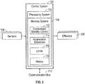
- FIG. 2 is a block diagram of a control system 100 of the gas turbine engine 10 of FIG. 1 in accordance with an embodiment of the disclosure.
- the control system 100 includes a processing system 102 and a memory system 104.
- the control system 100 interfaces with a plurality of sensors 106 that are configured to collect diagnostic and operational data related to performance of the gas turbine engine 10 of FIG. 1 .
- the sensors 106 can include one or more temperature sensors, pressure sensors, strain gauges, speed sensors, position sensors, accelerometers, and the like.
- the control system 100 can control a number of effectors 108 to control various subsystems of the gas turbine engine 10 of FIG.
- the effectors 108 can include actuators operable to open or close a plurality of vanes and/or one or more bleed valves that can adjust an acceleration rate of the of the gas turbine engine 10 of FIG. 1 .
- the memory system 104 can store instructions that are executed by one or more processors of the processing system 102 and data values.
- the executable instructions may be stored or organized in any manner and at any level of abstraction, such as in connection with a controlling and/or monitoring operation of the sensors 106 and effectors 108.
- the one or more processors of the processing system 102 can be any type of central processing unit (CPU), including a microprocessor, a digital signal processor (DSP), a microcontroller, an application specific integrated circuit (ASIC), a field programmable gate array (FPGA), or the like.
- the memory system 104 may include random access memory (RAM), read only memory (ROM), or other electronic, optical, magnetic, or any other computer readable medium onto which is stored data and algorithms in a non-transitory form.
- RAM random access memory
- ROM read only memory
- the processing system 102 can also interface with a communication bus 110 to send and receive data values and/or executable instructions, including aircraft level data and pilot commands.
- the control system 100 can include other interfaces (not depicted), such as power management, discrete input/output, wireless communication interfaces, and the like.
- the memory system 104 includes instructions for compressor stability control 112 to select and/or modify one or more acceleration schedules 114 with respect to limits 116.
- the acceleration schedules 114 can include a baseline acceleration schedule for normal operating conditions and one or more recovery acceleration schedules that provide a greater stall margin in case of a damaged engine condition, such as a bird strike event.
- the limits 116 can define when different instances of the acceleration schedules 114 should be selected or when control parameters should be adjusted to reduce an acceleration rate of the gas turbine engine 10 of FIG. 1 .
- the limits can define flight envelope parameters for altitude, power, speed, and the like, which may be interlocks to prevent selection of a reduced acceleration schedule in a lower power mode and/or a low altitude condition.
- the limits 116 may also map engine health condition to particular instances of the acceleration schedules 114, where a likely reduction of the stall line exists due to known damage.
- the limits 116 can also or alternatively limit other control aspects that reduce acceleration rate, such as by controlling flow through and out of the gas turbine engine 10 of FIG. 1 .
- the memory system 104 can also include a history data store 118 to track conditions and selection history of the acceleration schedules 114 to assist in subsequent analysis and future selection and/or modification of the acceleration schedules 114.
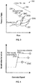
- FIG. 3 depicts an example of pressure versus flow relationships 200 in accordance with an embodiment of the disclosure.
- An operating line 202 includes an example of an attempt to accelerate the gas turbine engine 10 of FIG. 1 towards condition 206A may result in stalling the gas turbine engine 10 before reaching the normal stall line 204, where the control system 100 of FIG. 2 initially selects normal acceleration schedule 208A of FIG. 4 ,
- the control system 100 of FIG. 2 can determine at least one performance parameter using sensors 106 of FIG. 2 to detect or predict a stall. For instance, one or more of a pressure ratio of the gas turbine engine 10, a rate of speed change of the gas turbine engine 10, and a temperature of the gas turbine engine 10 can be used to detect or predict a stall according to known methods.
- the control system 100 of FIG. 2 can incrementally reduce the acceleration schedule 208A to acceleration schedule 208B of FIG. 4 , for instance, as a lookup or scaling operation in the acceleration schedules 114 of FIG. 2 . If while operating according to acceleration schedule 208B as a stall recovery schedule, another stall condition 206B of FIG. 3 is detected or predicted, a further incremental reduction to acceleration schedule 208C of FIG. 4 can be made. Acceleration schedule 208C may result in stall condition 206C of FIG. 3 along damaged engine stall line 210 of FIG.
- the damaged engine stall line 210 may be predicted based on detected damage to the gas turbine engine 10 and/or identifying at least one of the stall conditions 206A-206C.
- FIGS. 3 and 4 depict two stall recovery acceleration schedules and associated stall conditions, it will be understood that any number of additional acceleration schedules can be incorporated in various embodiments.
- FIG. 5 is a flow chart illustrating a method 300 for progressive stall recovery of the gas turbine engine 10 of FIG. 1 in accordance with an embodiment. The method 300 of FIG. 5 is described in reference to FIGS. 1 to 4 .
- control system 100 determines at least one performance parameter associated with a stall condition of the gas turbine engine 10.
- the at least one performance parameter can include one or more of: a pressure ratio of the gas turbine engine 10, a rate of speed change of the gas turbine engine 10, and a temperature of the gas turbine engine 10.
- the control system 100 can incrementally reduce an acceleration rate of the gas turbine engine 10 based on detecting a degraded stall line limit according to the at least one performance parameter. Detecting the degraded stall line limit can include detecting a stall of the gas turbine engine 10. The acceleration rate can be incrementally reduced based on a series of detected stalls of the gas turbine engine 10.
- Incremental reduction of an acceleration schedule can be limited to a power setting range in a take-off envelope, such as a higher power setting above idle where sub-idle speeds are avoided.
- the acceleration schedule can be selected from acceleration schedules 114 based on a targeted reduction in the acceleration rate below a damaged engine stall line 210.
- the acceleration rate can be adjusted by performing one or more of: closing a plurality of vanes of the gas turbine engine 10 and opening one or more bleed valves of the gas turbine engine 10.
- the damaged engine stall line 210 can be determined based on one or more of: a damage assessment of the gas turbine engine 10 and at least one detected stall of the gas turbine engine 10.
Landscapes
- Engineering & Computer Science (AREA)
- Mechanical Engineering (AREA)
- General Engineering & Computer Science (AREA)
- Chemical & Material Sciences (AREA)
- Combustion & Propulsion (AREA)
- Physics & Mathematics (AREA)
- Fluid Mechanics (AREA)
- Aviation & Aerospace Engineering (AREA)
- Control Of Turbines (AREA)
Claims (12)
- Steuerungs-(100)-System für ein Gasturbinentriebwerk (10), wobei das Steuerungssystem (100) Folgendes umfasst:ein Verarbeitungssystem (102), das dazu konfiguriert ist, eine Geschwindigkeit des Gasturbinentriebwerks zu steuern; undein Speichersystem (104), das dazu konfiguriert ist, Anweisungen zu speichern, die durch das Verarbeitungssystem (102) ausführbar sind, um mindestens einen Leistungsparameter zu bestimmen, der mit einem Strömungsabrisszustand des Gasturbinentriebwerks assoziiert ist, und um eine Beschleunigungsrate des Gasturbinentriebwerks auf der Basis eines Detektierens einer herabgesetzten Strömungsabrissliniengrenze gemäß dem mindestens einen Leistungsparameter schrittweise anzupassen, wobei ein Beschleunigungsschema (114) basierend auf einer Reihe von detektierten Strömungsabrissen des Gasturbinentriebwerks schrittweise reduziert wird, und wobei eine schrittweise Reduzierung des Beschleunigungsschemas (114) auf einen Energieeinstellungsbereich in einer Abflugenveloppe begrenzt ist.
- Steuerungssystem (100) nach Anspruch 1, wobei der mindestens eine Leistungsparameter eines oder mehrere der Folgenden umfasst: ein Druckverhältnis des Gasturbinentriebwerks (10), eine Geschwindigkeitsveränderungsrate des Gasturbinentriebwerks und eine Temperatur des Gasturbinentriebwerks.
- Steuerungssystem (100) nach Anspruch 1 oder Anspruch 2, wobei das Detektieren der herabgesetzten Strömungsabrissliniengrenze ein Detektieren eines Strömungsabrisses des Gasturbinentriebwerks (10) umfasst.
- Steuerungssystem (100) nach einem der vorhergehenden Ansprüche, wobei die Beschleunigungsrate durch ein Durchführen von einem oder mehreren der Folgenden angepasst wird: Schließen einer Vielzahl von Leitschaufeln des Gasturbinentriebwerks (10) und Öffnen von einem oder mehreren Ablassventilen des Gasturbinentriebwerks.
- Steuerungssystem (100) nach einem der vorhergehenden Ansprüche, wobei das Beschleunigungsschema (114) auf der Basis einer angestrebten Reduzierung der Beschleunigungsrate unter eine Strömungsabrisslinie eines beschädigten Triebwerks ausgewählt ist.
- Steuerungssystem (100) nach Anspruch 5, wobei die Strömungsabrisslinie eines beschädigten Triebwerks auf der Basis von einem oder mehreren bestimmt wird von: einer Beschädigungsbeurteilung des Gasturbinentriebwerks (10) und mindestens einem detektierten Strömungsabriss des Gasturbinentriebwerks.
- Gasturbinentriebwerk (10) eines Luftfahrzeugs, wobei das Gasturbinentriebwerk Folgendes umfasst:einen Verdichterbereich (24);einen Turbinenbereich (28); unddas Steuerungssystem (100) nach einem der vorhergehenden Ansprüche, wobei das Steuerungssystem (100) dazu konfiguriert ist, eine Geschwindigkeit einer Welle (30, 32) zu steuern, die den Verdichterbereich (24) und den Turbinenbereich (28) verbindet.
- Verfahren zur progressiven Strömungsabrisswiederherstellung eines Gasturbinentriebwerks (10), wobei das Verfahren Folgendes umfasst:Bestimmen durch ein Steuerungssystem (100) von mindestens einem Leistungsparameter, der mit einem Strömungsabrisszustand des Gasturbinentriebwerks (10) assoziiert ist; undschrittweises Reduzieren einer Beschleunigungsrate des Gasturbinentriebwerks (10) auf der Basis eines Detektierens einer herabgesetzten Strömungsabrissliniengrenze gemäß dem mindestens einen Leistungsparameter, dadurch gekennzeichnet, dass ein Beschleunigungsschema (114) auf der Basis einer Reihe von detektierten Strömungsabrissen des Gasturbinentriebwerks (10) schrittweise reduziert wird, und wobei eine schrittweise Reduzierung des Beschleunigungsschemas (114) auf einen Energieeinstellungsbereich in einer Abflugenveloppe begrenzt ist.
- Verfahren nach Anspruch 8, wobei der mindestens eine Leistungsparameter eines oder mehrere der Folgenden umfasst: ein Druckverhältnis des Gasturbinentriebwerks (10), eine Geschwindigkeitsveränderungsrate des Gasturbinentriebwerks und eine Temperatur des Gasturbinentriebwerks.
- Verfahren nach Anspruch 8 oder 9, wobei das Detektieren der herabgesetzten Strömungsabrissliniengrenze ein Detektieren eines Strömungsabrisses des Gasturbinentriebwerks (10) umfasst.
- Verfahren nach einem der Ansprüche 8 bis 10, wobei die Beschleunigungsrate durch ein Durchführen von einem oder mehreren der Folgenden angepasst wird: Schließen einer Vielzahl von Leitschaufeln des Gasturbinentriebwerks (10) und Öffnen von einem oder mehreren Ablassventilen des Gasturbinentriebwerks.
- Verfahren nach einem der Ansprüche 8 bis 11, wobei das Beschleunigungsschema (114) auf der Basis einer angestrebten Beschleunigungsratenreduzierung unter eine Strömungsabrisslinie eines beschädigten Triebwerks ausgewählt ist, und wobei die Strömungsabrisslinie eines beschädigten Triebwerks auf der Basis von einem oder mehreren der Folgenden bestimmt wird: einer Beschädigungsbeurteilung des Gasturbinentriebwerks (10) und mindestens einem detektierten Strömungsabriss des Gasturbinentriebwerks.
Applications Claiming Priority (1)
| Application Number | Priority Date | Filing Date | Title |
|---|---|---|---|
| US15/258,197 US10023319B2 (en) | 2016-09-07 | 2016-09-07 | Gas turbine engine with progressive stall recovery |
Publications (2)
| Publication Number | Publication Date |
|---|---|
| EP3293385A1 EP3293385A1 (de) | 2018-03-14 |
| EP3293385B1 true EP3293385B1 (de) | 2019-07-03 |
Family
ID=59829189
Family Applications (1)
| Application Number | Title | Priority Date | Filing Date |
|---|---|---|---|
| EP17189489.2A Active EP3293385B1 (de) | 2016-09-07 | 2017-09-05 | Gasturbinentriebwerk mit progressiver strömungsabrisswiederherstellung |
Country Status (2)
| Country | Link |
|---|---|
| US (1) | US10023319B2 (de) |
| EP (1) | EP3293385B1 (de) |
Families Citing this family (11)
| Publication number | Priority date | Publication date | Assignee | Title |
|---|---|---|---|---|
| US10815904B2 (en) | 2019-03-06 | 2020-10-27 | General Electric Company | Prognostic health management control for adaptive operability recovery for turbine engines |
| US20210016888A1 (en) * | 2019-07-15 | 2021-01-21 | United Technologies Corporation | Modulated combustor bypass for hybrid idle |
| US11539316B2 (en) | 2019-07-30 | 2022-12-27 | General Electric Company | Active stability control of compression systems utilizing electric machines |
| US12516635B2 (en) | 2020-08-31 | 2026-01-06 | General Electric Company | Compressor stall mitigation |
| US11725594B2 (en) | 2020-08-31 | 2023-08-15 | General Electric Company | Hybrid electric engine speed regulation |
| US12031479B2 (en) * | 2020-08-31 | 2024-07-09 | General Electric Company | Hybrid electric propulsion system load share |
| US11873081B2 (en) | 2021-06-09 | 2024-01-16 | Textron Innovations Inc. | Supplemental engine power control |
| US12459659B2 (en) | 2022-03-07 | 2025-11-04 | General Electric Company | Method and apparatus for controlling electrical machines operating with a turbine engine |
| US12077308B2 (en) | 2022-04-14 | 2024-09-03 | Textron Innovations Inc. | Supplemental engine transition control |
| US12054245B2 (en) * | 2022-07-18 | 2024-08-06 | Textron Innovations Inc. | Optimizing usage of supplemental engine power |
| US12006880B2 (en) | 2022-09-12 | 2024-06-11 | General Electric Company | High bandwidth control of turbofan/turboprop thrust response using embedded electric machines |
Family Cites Families (7)
| Publication number | Priority date | Publication date | Assignee | Title |
|---|---|---|---|---|
| US4507915A (en) | 1981-04-30 | 1985-04-02 | Allied Corporation | Stall detector and surge prevention feature for a gas turbine engine |
| US4603546A (en) | 1985-07-16 | 1986-08-05 | Rolls-Royce Limited | Control systems for gas turbine aeroengines |
| US4984425A (en) | 1989-05-30 | 1991-01-15 | United Technologies Corporation | Acceleration control for a gas turbine engine |
| US6364602B1 (en) | 2000-01-06 | 2002-04-02 | General Electric Company | Method of air-flow measurement and active operating limit line management for compressor surge avoidance |
| US20080234994A1 (en) * | 2007-03-22 | 2008-09-25 | General Electric Company | Method and system for accommodating deterioration characteristics of machines |
| FR2986571B1 (fr) | 2012-02-06 | 2014-02-21 | Eurocopter France | Dispositif et procede de regulation d'un turbomoteur, et aeronef |
| US10436059B2 (en) * | 2014-05-12 | 2019-10-08 | Simmonds Precision Products, Inc. | Rotating stall detection through ratiometric measure of the sub-synchronous band spectrum |
-
2016
- 2016-09-07 US US15/258,197 patent/US10023319B2/en active Active
-
2017
- 2017-09-05 EP EP17189489.2A patent/EP3293385B1/de active Active
Non-Patent Citations (1)
| Title |
|---|
| None * |
Also Published As
| Publication number | Publication date |
|---|---|
| EP3293385A1 (de) | 2018-03-14 |
| US20180065755A1 (en) | 2018-03-08 |
| US10023319B2 (en) | 2018-07-17 |
Similar Documents
| Publication | Publication Date | Title |
|---|---|---|
| EP3293385B1 (de) | Gasturbinentriebwerk mit progressiver strömungsabrisswiederherstellung | |
| EP3418504B1 (de) | Verfahren zur zustandsüberwachung und gasturbinentriebwerk | |
| US11473496B2 (en) | Transient operation control of a hybrid gas turbine engine | |
| EP3205834B1 (de) | Anlassabschwächung für gebogenen rotor in einem gasturbinenmotor | |
| EP3205859B1 (de) | System zur zur verhinderung von rotorkrümmung für einen gasturbinenmotor | |
| EP3205858B1 (de) | Modifizierte anlasssequenz eines gasturbinenmotors | |
| EP3205837B1 (de) | Anlassabschwächung für gebogenen rotor in einem gasturbinenmotor unter verwendung von flugzeugabgeleiteten parametern und entsprechendes verfahren | |
| EP3205835B1 (de) | Start eines gebogenen rotors mit direkter temperaturmessung | |
| US10443543B2 (en) | High compressor build clearance reduction | |
| US10794281B2 (en) | Gas turbine engine having instrumented airflow path components | |
| EP3296522B1 (de) | Motorübergreifende koordination während des anlassens eines gasturbinenmotors | |
| US12140083B2 (en) | Adaptive model predictive control for hybrid electric propulsion | |
| US10378376B2 (en) | Method and system for adjusting an operating parameter as a function of component health | |
| EP3273007A1 (de) | Luftzufuhrsteuerung während der überwachung eines gasturbinenmotors | |
| EP3451085B1 (de) | Verfahren zur auswahl optimaler motorbetriebsbedingungen zur erzeugung linearisierter modelle für bordsteuerung und schätzung | |
| EP3767090B1 (de) | Steuerung der betriebsfähigkeit eines kompressors für einen hybriden elektrischen antrieb | |
| US11773743B2 (en) | Model-based rotor speed keep out zone control | |
| US11557995B2 (en) | Aircraft engine power-assist start stability control | |
| CN115126554A (zh) | 配有使用电机管理转子模式的控制系统的燃气涡轮发动机 |
Legal Events
| Date | Code | Title | Description |
|---|---|---|---|
| PUAI | Public reference made under article 153(3) epc to a published international application that has entered the european phase |
Free format text: ORIGINAL CODE: 0009012 |
|
| STAA | Information on the status of an ep patent application or granted ep patent |
Free format text: STATUS: THE APPLICATION HAS BEEN PUBLISHED |
|
| AK | Designated contracting states |
Kind code of ref document: A1 Designated state(s): AL AT BE BG CH CY CZ DE DK EE ES FI FR GB GR HR HU IE IS IT LI LT LU LV MC MK MT NL NO PL PT RO RS SE SI SK SM TR |
|
| AX | Request for extension of the european patent |
Extension state: BA ME |
|
| STAA | Information on the status of an ep patent application or granted ep patent |
Free format text: STATUS: REQUEST FOR EXAMINATION WAS MADE |
|
| 17P | Request for examination filed |
Effective date: 20180914 |
|
| RBV | Designated contracting states (corrected) |
Designated state(s): AL AT BE BG CH CY CZ DE DK EE ES FI FR GB GR HR HU IE IS IT LI LT LU LV MC MK MT NL NO PL PT RO RS SE SI SK SM TR |
|
| GRAP | Despatch of communication of intention to grant a patent |
Free format text: ORIGINAL CODE: EPIDOSNIGR1 |
|
| STAA | Information on the status of an ep patent application or granted ep patent |
Free format text: STATUS: GRANT OF PATENT IS INTENDED |
|
| INTG | Intention to grant announced |
Effective date: 20190107 |
|
| GRAS | Grant fee paid |
Free format text: ORIGINAL CODE: EPIDOSNIGR3 |
|
| GRAA | (expected) grant |
Free format text: ORIGINAL CODE: 0009210 |
|
| STAA | Information on the status of an ep patent application or granted ep patent |
Free format text: STATUS: THE PATENT HAS BEEN GRANTED |
|
| AK | Designated contracting states |
Kind code of ref document: B1 Designated state(s): AL AT BE BG CH CY CZ DE DK EE ES FI FR GB GR HR HU IE IS IT LI LT LU LV MC MK MT NL NO PL PT RO RS SE SI SK SM TR |
|
| REG | Reference to a national code |
Ref country code: GB Ref legal event code: FG4D |
|
| REG | Reference to a national code |
Ref country code: CH Ref legal event code: EP Ref country code: AT Ref legal event code: REF Ref document number: 1151297 Country of ref document: AT Kind code of ref document: T Effective date: 20190715 |
|
| REG | Reference to a national code |
Ref country code: IE Ref legal event code: FG4D |
|
| REG | Reference to a national code |
Ref country code: DE Ref legal event code: R096 Ref document number: 602017004989 Country of ref document: DE |
|
| REG | Reference to a national code |
Ref country code: NL Ref legal event code: MP Effective date: 20190703 |
|
| REG | Reference to a national code |
Ref country code: LT Ref legal event code: MG4D |
|
| REG | Reference to a national code |
Ref country code: AT Ref legal event code: MK05 Ref document number: 1151297 Country of ref document: AT Kind code of ref document: T Effective date: 20190703 |
|
| PG25 | Lapsed in a contracting state [announced via postgrant information from national office to epo] |
Ref country code: NO Free format text: LAPSE BECAUSE OF FAILURE TO SUBMIT A TRANSLATION OF THE DESCRIPTION OR TO PAY THE FEE WITHIN THE PRESCRIBED TIME-LIMIT Effective date: 20191003 Ref country code: BG Free format text: LAPSE BECAUSE OF FAILURE TO SUBMIT A TRANSLATION OF THE DESCRIPTION OR TO PAY THE FEE WITHIN THE PRESCRIBED TIME-LIMIT Effective date: 20191003 Ref country code: NL Free format text: LAPSE BECAUSE OF FAILURE TO SUBMIT A TRANSLATION OF THE DESCRIPTION OR TO PAY THE FEE WITHIN THE PRESCRIBED TIME-LIMIT Effective date: 20190703 Ref country code: HR Free format text: LAPSE BECAUSE OF FAILURE TO SUBMIT A TRANSLATION OF THE DESCRIPTION OR TO PAY THE FEE WITHIN THE PRESCRIBED TIME-LIMIT Effective date: 20190703 Ref country code: SE Free format text: LAPSE BECAUSE OF FAILURE TO SUBMIT A TRANSLATION OF THE DESCRIPTION OR TO PAY THE FEE WITHIN THE PRESCRIBED TIME-LIMIT Effective date: 20190703 Ref country code: FI Free format text: LAPSE BECAUSE OF FAILURE TO SUBMIT A TRANSLATION OF THE DESCRIPTION OR TO PAY THE FEE WITHIN THE PRESCRIBED TIME-LIMIT Effective date: 20190703 Ref country code: LT Free format text: LAPSE BECAUSE OF FAILURE TO SUBMIT A TRANSLATION OF THE DESCRIPTION OR TO PAY THE FEE WITHIN THE PRESCRIBED TIME-LIMIT Effective date: 20190703 Ref country code: CZ Free format text: LAPSE BECAUSE OF FAILURE TO SUBMIT A TRANSLATION OF THE DESCRIPTION OR TO PAY THE FEE WITHIN THE PRESCRIBED TIME-LIMIT Effective date: 20190703 Ref country code: PT Free format text: LAPSE BECAUSE OF FAILURE TO SUBMIT A TRANSLATION OF THE DESCRIPTION OR TO PAY THE FEE WITHIN THE PRESCRIBED TIME-LIMIT Effective date: 20191104 Ref country code: AT Free format text: LAPSE BECAUSE OF FAILURE TO SUBMIT A TRANSLATION OF THE DESCRIPTION OR TO PAY THE FEE WITHIN THE PRESCRIBED TIME-LIMIT Effective date: 20190703 |
|
| PG25 | Lapsed in a contracting state [announced via postgrant information from national office to epo] |
Ref country code: ES Free format text: LAPSE BECAUSE OF FAILURE TO SUBMIT A TRANSLATION OF THE DESCRIPTION OR TO PAY THE FEE WITHIN THE PRESCRIBED TIME-LIMIT Effective date: 20190703 Ref country code: AL Free format text: LAPSE BECAUSE OF FAILURE TO SUBMIT A TRANSLATION OF THE DESCRIPTION OR TO PAY THE FEE WITHIN THE PRESCRIBED TIME-LIMIT Effective date: 20190703 Ref country code: LV Free format text: LAPSE BECAUSE OF FAILURE TO SUBMIT A TRANSLATION OF THE DESCRIPTION OR TO PAY THE FEE WITHIN THE PRESCRIBED TIME-LIMIT Effective date: 20190703 Ref country code: IS Free format text: LAPSE BECAUSE OF FAILURE TO SUBMIT A TRANSLATION OF THE DESCRIPTION OR TO PAY THE FEE WITHIN THE PRESCRIBED TIME-LIMIT Effective date: 20191103 Ref country code: RS Free format text: LAPSE BECAUSE OF FAILURE TO SUBMIT A TRANSLATION OF THE DESCRIPTION OR TO PAY THE FEE WITHIN THE PRESCRIBED TIME-LIMIT Effective date: 20190703 Ref country code: GR Free format text: LAPSE BECAUSE OF FAILURE TO SUBMIT A TRANSLATION OF THE DESCRIPTION OR TO PAY THE FEE WITHIN THE PRESCRIBED TIME-LIMIT Effective date: 20191004 |
|
| PG25 | Lapsed in a contracting state [announced via postgrant information from national office to epo] |
Ref country code: TR Free format text: LAPSE BECAUSE OF FAILURE TO SUBMIT A TRANSLATION OF THE DESCRIPTION OR TO PAY THE FEE WITHIN THE PRESCRIBED TIME-LIMIT Effective date: 20190703 |
|
| PG25 | Lapsed in a contracting state [announced via postgrant information from national office to epo] |
Ref country code: RO Free format text: LAPSE BECAUSE OF FAILURE TO SUBMIT A TRANSLATION OF THE DESCRIPTION OR TO PAY THE FEE WITHIN THE PRESCRIBED TIME-LIMIT Effective date: 20190703 Ref country code: PL Free format text: LAPSE BECAUSE OF FAILURE TO SUBMIT A TRANSLATION OF THE DESCRIPTION OR TO PAY THE FEE WITHIN THE PRESCRIBED TIME-LIMIT Effective date: 20190703 Ref country code: EE Free format text: LAPSE BECAUSE OF FAILURE TO SUBMIT A TRANSLATION OF THE DESCRIPTION OR TO PAY THE FEE WITHIN THE PRESCRIBED TIME-LIMIT Effective date: 20190703 Ref country code: IT Free format text: LAPSE BECAUSE OF FAILURE TO SUBMIT A TRANSLATION OF THE DESCRIPTION OR TO PAY THE FEE WITHIN THE PRESCRIBED TIME-LIMIT Effective date: 20190703 Ref country code: DK Free format text: LAPSE BECAUSE OF FAILURE TO SUBMIT A TRANSLATION OF THE DESCRIPTION OR TO PAY THE FEE WITHIN THE PRESCRIBED TIME-LIMIT Effective date: 20190703 |
|
| PG25 | Lapsed in a contracting state [announced via postgrant information from national office to epo] |
Ref country code: MC Free format text: LAPSE BECAUSE OF FAILURE TO SUBMIT A TRANSLATION OF THE DESCRIPTION OR TO PAY THE FEE WITHIN THE PRESCRIBED TIME-LIMIT Effective date: 20190703 Ref country code: SM Free format text: LAPSE BECAUSE OF FAILURE TO SUBMIT A TRANSLATION OF THE DESCRIPTION OR TO PAY THE FEE WITHIN THE PRESCRIBED TIME-LIMIT Effective date: 20190703 Ref country code: IS Free format text: LAPSE BECAUSE OF FAILURE TO SUBMIT A TRANSLATION OF THE DESCRIPTION OR TO PAY THE FEE WITHIN THE PRESCRIBED TIME-LIMIT Effective date: 20200224 Ref country code: SK Free format text: LAPSE BECAUSE OF FAILURE TO SUBMIT A TRANSLATION OF THE DESCRIPTION OR TO PAY THE FEE WITHIN THE PRESCRIBED TIME-LIMIT Effective date: 20190703 |
|
| REG | Reference to a national code |
Ref country code: DE Ref legal event code: R097 Ref document number: 602017004989 Country of ref document: DE |
|
| PLBE | No opposition filed within time limit |
Free format text: ORIGINAL CODE: 0009261 |
|
| STAA | Information on the status of an ep patent application or granted ep patent |
Free format text: STATUS: NO OPPOSITION FILED WITHIN TIME LIMIT |
|
| PG2D | Information on lapse in contracting state deleted |
Ref country code: IS |
|
| PG25 | Lapsed in a contracting state [announced via postgrant information from national office to epo] |
Ref country code: IE Free format text: LAPSE BECAUSE OF NON-PAYMENT OF DUE FEES Effective date: 20190905 Ref country code: LU Free format text: LAPSE BECAUSE OF NON-PAYMENT OF DUE FEES Effective date: 20190905 |
|
| REG | Reference to a national code |
Ref country code: BE Ref legal event code: MM Effective date: 20190930 |
|
| 26N | No opposition filed |
Effective date: 20200603 |
|
| PG25 | Lapsed in a contracting state [announced via postgrant information from national office to epo] |
Ref country code: BE Free format text: LAPSE BECAUSE OF NON-PAYMENT OF DUE FEES Effective date: 20190930 Ref country code: SI Free format text: LAPSE BECAUSE OF FAILURE TO SUBMIT A TRANSLATION OF THE DESCRIPTION OR TO PAY THE FEE WITHIN THE PRESCRIBED TIME-LIMIT Effective date: 20190703 |
|
| REG | Reference to a national code |
Ref country code: CH Ref legal event code: PL |
|
| PG25 | Lapsed in a contracting state [announced via postgrant information from national office to epo] |
Ref country code: CY Free format text: LAPSE BECAUSE OF FAILURE TO SUBMIT A TRANSLATION OF THE DESCRIPTION OR TO PAY THE FEE WITHIN THE PRESCRIBED TIME-LIMIT Effective date: 20190703 |
|
| PG25 | Lapsed in a contracting state [announced via postgrant information from national office to epo] |
Ref country code: MT Free format text: LAPSE BECAUSE OF FAILURE TO SUBMIT A TRANSLATION OF THE DESCRIPTION OR TO PAY THE FEE WITHIN THE PRESCRIBED TIME-LIMIT Effective date: 20190703 Ref country code: HU Free format text: LAPSE BECAUSE OF FAILURE TO SUBMIT A TRANSLATION OF THE DESCRIPTION OR TO PAY THE FEE WITHIN THE PRESCRIBED TIME-LIMIT; INVALID AB INITIO Effective date: 20170905 |
|
| PG25 | Lapsed in a contracting state [announced via postgrant information from national office to epo] |
Ref country code: CH Free format text: LAPSE BECAUSE OF NON-PAYMENT OF DUE FEES Effective date: 20200930 Ref country code: LI Free format text: LAPSE BECAUSE OF NON-PAYMENT OF DUE FEES Effective date: 20200930 |
|
| PG25 | Lapsed in a contracting state [announced via postgrant information from national office to epo] |
Ref country code: MK Free format text: LAPSE BECAUSE OF FAILURE TO SUBMIT A TRANSLATION OF THE DESCRIPTION OR TO PAY THE FEE WITHIN THE PRESCRIBED TIME-LIMIT Effective date: 20190703 |
|
| REG | Reference to a national code |
Ref country code: DE Ref legal event code: R081 Ref document number: 602017004989 Country of ref document: DE Owner name: RAYTHEON TECHNOLOGIES CORPORATION (N.D.GES.D.S, US Free format text: FORMER OWNER: UNITED TECHNOLOGIES CORPORATION, FARMINGTON, CONN., US Ref country code: DE Ref legal event code: R081 Ref document number: 602017004989 Country of ref document: DE Owner name: RTX CORPORATION (N.D.GES.D. STAATES DELAWARE),, US Free format text: FORMER OWNER: UNITED TECHNOLOGIES CORPORATION, FARMINGTON, CONN., US |
|
| P01 | Opt-out of the competence of the unified patent court (upc) registered |
Effective date: 20230520 |
|
| PGFP | Annual fee paid to national office [announced via postgrant information from national office to epo] |
Ref country code: DE Payment date: 20250820 Year of fee payment: 9 |
|
| PGFP | Annual fee paid to national office [announced via postgrant information from national office to epo] |
Ref country code: GB Payment date: 20250822 Year of fee payment: 9 |
|
| PGFP | Annual fee paid to national office [announced via postgrant information from national office to epo] |
Ref country code: FR Payment date: 20250821 Year of fee payment: 9 |
|
| REG | Reference to a national code |
Ref country code: DE Ref legal event code: R081 Ref document number: 602017004989 Country of ref document: DE Owner name: RTX CORPORATION (N.D.GES.D. STAATES DELAWARE),, US Free format text: FORMER OWNER: RAYTHEON TECHNOLOGIES CORPORATION (N.D.GES.D.STAATES DELAWARE), ARLINGTON, VA, US |