EP3293401B1 - Düse mit sicherungsmutter - Google Patents
Düse mit sicherungsmutter Download PDFInfo
- Publication number
- EP3293401B1 EP3293401B1 EP16461555.1A EP16461555A EP3293401B1 EP 3293401 B1 EP3293401 B1 EP 3293401B1 EP 16461555 A EP16461555 A EP 16461555A EP 3293401 B1 EP3293401 B1 EP 3293401B1
- Authority
- EP
- European Patent Office
- Prior art keywords
- nozzle
- locking member
- tube
- cut
- rotation
- Prior art date
- Legal status (The legal status is an assumption and is not a legal conclusion. Google has not performed a legal analysis and makes no representation as to the accuracy of the status listed.)
- Active
Links
Images



Classifications
-
- F—MECHANICAL ENGINEERING; LIGHTING; HEATING; WEAPONS; BLASTING
- F15—FLUID-PRESSURE ACTUATORS; HYDRAULICS OR PNEUMATICS IN GENERAL
- F15B—SYSTEMS ACTING BY MEANS OF FLUIDS IN GENERAL; FLUID-PRESSURE ACTUATORS, e.g. SERVOMOTORS; DETAILS OF FLUID-PRESSURE SYSTEMS, NOT OTHERWISE PROVIDED FOR
- F15B13/00—Details of servomotor systems ; Valves for servomotor systems
- F15B13/02—Fluid distribution or supply devices characterised by their adaptation to the control of servomotors
- F15B13/04—Fluid distribution or supply devices characterised by their adaptation to the control of servomotors for use with a single servomotor
- F15B13/042—Fluid distribution or supply devices characterised by their adaptation to the control of servomotors for use with a single servomotor operated by fluid pressure
- F15B13/043—Fluid distribution or supply devices characterised by their adaptation to the control of servomotors for use with a single servomotor operated by fluid pressure with electrically-controlled pilot valves
- F15B13/0438—Fluid distribution or supply devices characterised by their adaptation to the control of servomotors for use with a single servomotor operated by fluid pressure with electrically-controlled pilot valves the pilot valves being of the nozzle-flapper type
-
- F—MECHANICAL ENGINEERING; LIGHTING; HEATING; WEAPONS; BLASTING
- F15—FLUID-PRESSURE ACTUATORS; HYDRAULICS OR PNEUMATICS IN GENERAL
- F15B—SYSTEMS ACTING BY MEANS OF FLUIDS IN GENERAL; FLUID-PRESSURE ACTUATORS, e.g. SERVOMOTORS; DETAILS OF FLUID-PRESSURE SYSTEMS, NOT OTHERWISE PROVIDED FOR
- F15B13/00—Details of servomotor systems ; Valves for servomotor systems
- F15B13/02—Fluid distribution or supply devices characterised by their adaptation to the control of servomotors
- F15B13/04—Fluid distribution or supply devices characterised by their adaptation to the control of servomotors for use with a single servomotor
- F15B13/042—Fluid distribution or supply devices characterised by their adaptation to the control of servomotors for use with a single servomotor operated by fluid pressure
-
- F—MECHANICAL ENGINEERING; LIGHTING; HEATING; WEAPONS; BLASTING
- F15—FLUID-PRESSURE ACTUATORS; HYDRAULICS OR PNEUMATICS IN GENERAL
- F15B—SYSTEMS ACTING BY MEANS OF FLUIDS IN GENERAL; FLUID-PRESSURE ACTUATORS, e.g. SERVOMOTORS; DETAILS OF FLUID-PRESSURE SYSTEMS, NOT OTHERWISE PROVIDED FOR
- F15B9/00—Servomotors with follow-up action, e.g. obtained by feed-back control, i.e. in which the position of the actuated member conforms with that of the controlling member
- F15B9/02—Servomotors with follow-up action, e.g. obtained by feed-back control, i.e. in which the position of the actuated member conforms with that of the controlling member with servomotors of the reciprocatable or oscillatable type
- F15B9/06—Servomotors with follow-up action, e.g. obtained by feed-back control, i.e. in which the position of the actuated member conforms with that of the controlling member with servomotors of the reciprocatable or oscillatable type controlled by means using a fluid jet
- F15B9/07—Servomotors with follow-up action, e.g. obtained by feed-back control, i.e. in which the position of the actuated member conforms with that of the controlling member with servomotors of the reciprocatable or oscillatable type controlled by means using a fluid jet with electrical control means
-
- F—MECHANICAL ENGINEERING; LIGHTING; HEATING; WEAPONS; BLASTING
- F16—ENGINEERING ELEMENTS AND UNITS; GENERAL MEASURES FOR PRODUCING AND MAINTAINING EFFECTIVE FUNCTIONING OF MACHINES OR INSTALLATIONS; THERMAL INSULATION IN GENERAL
- F16K—VALVES; TAPS; COCKS; ACTUATING-FLOATS; DEVICES FOR VENTING OR AERATING
- F16K31/00—Actuating devices; Operating means; Releasing devices
- F16K31/12—Actuating devices; Operating means; Releasing devices actuated by fluid
- F16K31/36—Actuating devices; Operating means; Releasing devices actuated by fluid in which fluid from the circuit is constantly supplied to the fluid motor
-
- F—MECHANICAL ENGINEERING; LIGHTING; HEATING; WEAPONS; BLASTING
- F15—FLUID-PRESSURE ACTUATORS; HYDRAULICS OR PNEUMATICS IN GENERAL
- F15B—SYSTEMS ACTING BY MEANS OF FLUIDS IN GENERAL; FLUID-PRESSURE ACTUATORS, e.g. SERVOMOTORS; DETAILS OF FLUID-PRESSURE SYSTEMS, NOT OTHERWISE PROVIDED FOR
- F15B13/00—Details of servomotor systems ; Valves for servomotor systems
-
- F—MECHANICAL ENGINEERING; LIGHTING; HEATING; WEAPONS; BLASTING
- F15—FLUID-PRESSURE ACTUATORS; HYDRAULICS OR PNEUMATICS IN GENERAL
- F15B—SYSTEMS ACTING BY MEANS OF FLUIDS IN GENERAL; FLUID-PRESSURE ACTUATORS, e.g. SERVOMOTORS; DETAILS OF FLUID-PRESSURE SYSTEMS, NOT OTHERWISE PROVIDED FOR
- F15B13/00—Details of servomotor systems ; Valves for servomotor systems
- F15B13/02—Fluid distribution or supply devices characterised by their adaptation to the control of servomotors
- F15B13/04—Fluid distribution or supply devices characterised by their adaptation to the control of servomotors for use with a single servomotor
- F15B13/042—Fluid distribution or supply devices characterised by their adaptation to the control of servomotors for use with a single servomotor operated by fluid pressure
- F15B13/043—Fluid distribution or supply devices characterised by their adaptation to the control of servomotors for use with a single servomotor operated by fluid pressure with electrically-controlled pilot valves
- F15B13/0436—Fluid distribution or supply devices characterised by their adaptation to the control of servomotors for use with a single servomotor operated by fluid pressure with electrically-controlled pilot valves the pilot valves being of the steerable jet type
-
- F—MECHANICAL ENGINEERING; LIGHTING; HEATING; WEAPONS; BLASTING
- F15—FLUID-PRESSURE ACTUATORS; HYDRAULICS OR PNEUMATICS IN GENERAL
- F15B—SYSTEMS ACTING BY MEANS OF FLUIDS IN GENERAL; FLUID-PRESSURE ACTUATORS, e.g. SERVOMOTORS; DETAILS OF FLUID-PRESSURE SYSTEMS, NOT OTHERWISE PROVIDED FOR
- F15B19/00—Testing; Calibrating; Fault detection or monitoring; Simulation or modelling of fluid-pressure systems or apparatus not otherwise provided for
- F15B19/002—Calibrating
Definitions
- the examples described herein relate to a method for positioning and locking a nozzle in place within a valve body.
- the examples described herein also relate to a nozzle for positioning and locking in place within a servovalve body.
- the nozzles and method may be used, amongst other applications, in conjunction with a flapper/type servovalve.
- a hydraulic servovalve is a servo with a device (either flapper nozzle or jet pipe) used to position the servo.
- a device either flapper nozzle or jet pipe
- electrohydraulic servovalves When servovalves are controlled through an electrical signal they are called electrohydraulic servovalves.
- Servovalves are normally used when accurate position control is required and this position control may be achieved through a closed loop control system, consisting of command sensor, feedback sensor, digital or analogue controller, and the servovalve.
- Flapper nozzle systems for use in servovalves are well known. Flapper position is controlled by the electromagnetic torque motor and the torque developed by the torque motor is proportional to the applied current, with currents generally being in the milliamp range.
- a torque motor consists of two permanent magnets with a coil winding attached to a magnetically permeable armature. The armature is part of the flapper piece. When a current is applied to the coils, magnetic flux acting on the ends of the armature is developed. The direction of the magnetic flux (force) depends on the direction of the current. The magnetic flux will cause the armature tips to be attracted to the ends of the permanent magnets (current direction determines which magnetic pole is attracting and which one is repelling).
- Servovalves can be used to control hydraulic actuators or hydraulic motors.
- a servoactuator When a servoactuator is used to control an actuator, the servovalve and actuator combination are often referred to as a servoactuator.
- the main advantage of a servovalve is that a low power electrical signal can be used to accurately position an actuator or motor.
- the disadvantage is their complexity and the resulting costs of components consisting of many detail parts manufactured to very tight tolerances. Therefore, servovalves are generally only used when accurate position (or rate) control is required.
- Document GB1100149 discloses a servovalve having a nozzle which is press-fitted in a bore portion.
- a system for positioning a nozzle within a body is described herein.
- the body has a cylindrical bore defining an inner surface.
- the system comprises the nozzle that is to be positioned, the nozzle having a tubular shape and extending between a first end and a second end, with an outer cylindrical surface and an inner surface.
- the inner surface comprises a thread.
- the system further comprises a rotatable locking member which is provided within the nozzle.
- the locking member further comprises an outer circumferential surface having a thread that corresponds to the thread of the inner surface of the nozzle.
- the system further comprises means for providing torque to the locking member, to screw said locking member into and within said nozzle via said threaded surfaces, to thereby create a press-fit between said outer cylindrical surface of the nozzle and an inner surface of said body having said cylindrical bore.
- the first end of said nozzle may be configured to receive said locking member and the nozzle may comprise a first portion extending from said first end and in the direction of said second end.
- the first portion may comprise at least one cut-out section extending from said first end in the direction of the second end.
- the cut-out section may comprise a longitudinal shape extending axially in the direction of said nozzle second end.
- the nozzle may comprise a plurality of said cut-out sections provided around its circumference with material sections provided between said cut-out sections.
- said nozzle may comprise a second portion extending from said first portion, wherein said second portion comprises a solid tubular shape.
- said nozzle may have an inner diameter that decreases between said first end and said second end.
- said locking member may be ring shaped with a first side and a second side and the outer circumference of said ring shaped locking nut may decrease between said first side and said second side to provide a tapered outer surface that tapers at a first angle between said first side and said second side.
- said nozzle may have an inner diameter that decreases between said first end and said second end to provide a tapered inner surface that tapers at a second angle between said first end and said second end and said nozzle first end may be configured to receive said locking member second end.
- said outer cylindrical surface of said locking member may be in contact with said inner surface of said nozzle, and said first angle and said second angle may be equal.
- said inner surface of the nozzle and said outer surface of said locking member may be sized and/or shaped relative to each other so that said locking member fits within said nozzle with said tapered surfaces contacting each other.
- said locking member may be configured to be screwed so as to move axially in the direction of said nozzle second end.
- system may further comprise means for preventing rotation of said nozzle within said body when said torque is applied to said locking member.
- said means for preventing rotation of said nozzle within said body may comprise a tube extending from a first end to a second end, said second end of the anti-rotation tube comprising means for interlocking the second end of the tube with the first end of the nozzle.
- the means for interlocking may comprise at least one cut-out section at said second end of said anti-rotation tube and at least one cut-out section at said first end of said nozzle, said cut-out sections being shaped and sized so as to enable the two ends to slot together and interlock.
- said nozzle may be sized so as to fit within said body having said cylindrical bore so that said outer surface of said nozzle contacts the inner surface of said body.
- said body having a cylindrical bore may comprise a first material and said locking member may also comprise the same first material.
- the body having a cylindrical bore and/or locking member may comprise a first material and said nozzle may comprise a second material and said first material may be different to said second material.
- a method for positioning and fixing in place a nozzle within a body having a cylindrical bore defining an inner surface, the method comprising: positioning said nozzle within said cylindrical bore of said body, said nozzle having a tubular shape extending between a first end and a second end with an outer cylindrical surface and an inner surface, said inner surface comprising a thread, and providing a locking member within said nozzle, said locking member comprising an outer circumferential surface having a thread that corresponds to the thread of the inner surface of the nozzle and said method further comprising providing torque to said locking member to screw said locking member into and within said nozzle via said threaded surfaces to thereby create a press-fit between said outer cylindrical surface of the nozzle and an inner surface of said cylindrical bore of said body.
- the method may further comprise the step of said first end of said nozzle receiving said locking member, and further wherein said nozzle comprises a first portion extending from said first end and in the direction of said second end, said first portion and further comprising providing at least one cut-out section extending from said first end in the direction of the second end.
- the method may further comprise providing a plurality of said cut-out sections around the nozzle circumference and with wall sections between said cut-out sections.
- the method may further comprise the step of tapering the inner diameter of the nozzle so that it decreases between said first end and said second end.
- the outer surface of the locking member may be ring shaped with a first side and a second side and the method may further comprise the step of tapering, at a first angle, the outer surface of the ring shaped locking member so that the outer diameter of the locking member decreases between said first side and said second side at said first angle.
- the method may further comprise the step of tapering the inner surface of the nozzle so that the inner diameter of the nozzle decreases between said first end and said second end to provide a tapered inner surface that tapers at a second angle between said first end and said second end, said first angle and said second angle being equal.
- the method may further comprise the step of sizing and/or shaping the inner surface of the nozzle and the outer surface of said locking member relative to each other so that said locking member fits within said nozzle with said tapered surfaces contacting each other.
- the method may further comprise the step of rotating said locking member along a screw thread so as to move said locking member axially in the direction of said nozzle second end.
- the method may further comprise the step of providing a nozzle anti-rotation member having a first end and a second end and further comprising the step of, prior to the step of positioning the nozzle in place within the cylindrical bore of said body, connecting the second end of the nozzle anti-rotation member to the first end of the nozzle and inserting the nozzle into the cylindrical bore of said body by moving the anti-rotation member and nozzle axially within said cylindrical bore in the direction of the second end of the nozzle.
- the method may further comprise the step of fixing in position the first end of the anti-rotation member to thereby prevent rotation of said nozzle within said body when said torque is applied to said locking member.
- the anti-rotation member may comprise a tube extending from a first end to a second end, said second end of the anti-rotation tube comprising means for interlocking the second end of the tube with the first end of the nozzle.
- the means for interlocking may comprise at least one cut-out section at said second end of said anti-rotation tube and at least one cut-out section at said first end of said nozzle, said cut-out sections being shaped and sized so as to enable the two ends to slot together and interlock.
- FIG. 1 An example of a known type of double flapper nozzle 100 that may be used with a servovalve is depicted, for example, in figure 1.
- Figure 1 does not depict the entire servovalve, but only the main features of the nozzles and flapper.
- the servovalve device has a torque motor having an armature 17 with one or more coils 16, flapper 14 and nozzles 15.
- fluid pressure is supplied to the points 10A and 10B.
- Orifices 13A and 13B are formed on each side between the flapper 14 and the opposing nozzles 15. As long as the flapper is centered, the orifices 13A and 13B are the same on both sides and the pressure drop to the return is the same.
- Pressure at 10A equals the pressure at 10B, and the spool connected to the servo (not shown) is in force balance. If the torque motor 17 rotates the flapper 14 clockwise then the orifice 13A on the left is smaller than the orifice 13B on the right, and the pressure at 10A will be greater than the pressure at 10B. This pressure difference shifts the spool of the servovalve to the right. As the spool shifts, it deflects a feedback spring connected to the servo (not shown). The spool continues to move until the spring force produces a torque that equals the electromagnetic torque produced by the current flowing through the coil 16 around the armature 17.
- the armature 17 is moved back to the center position, the flapper 14 is centered, the pressure becomes equal at 10A and 10B, and the spool stops.
- the spool of the servovalve stays in this position until the current through the coil 16 changes. Because of the feedback spring, the spool has a unique position corresponding to each current through the coil 17 ranging from 0 to rated current. At rated current, the spool is shifted to its full open position.
- the circumferential area created by the flapper distance to the nozzle must be smaller than the nozzle diameter, such that the circumferential area controls flow and not the nozzle diameter. In this way, the flow area varies linearly with flapper position. Also, the torque motor materials, windings and overall design features lead to accurate control of torque such that small movements of the flapper are possible. This leads to accurate control of the pilot spool, which in turns provides accurate control of the actuator.
- the goal of the flapper and nozzles is to control the pressure acting on both sides of the pilot spool.
- the flapper When the flapper is in the neutral position, the nozzle flow areas are equal and the pressures on both side of the spool are equal.
- Figure 2 depicts a cross section of a known type of nozzle such as that described with reference to figure 1 .
- the calibration is carried out by a push rod (not shown) that is connected with the nozzle 15 by a nozzle internal thread 21.
- the servovalve is calibrated by movement of the nozzles 15 into the correct position within the body 20 of the servovalve. Once the nozzle 15 is in the correct position and calibration has been completed, it is no longer possible to then move the nozzle at a later date. The nozzle 15 is then only held in position within the housing or body 20 of the servovalve via a constant press fit.
- a nozzle with a locking member and a new method and means for positioning and locking in place a nozzle within the body of a servovalve will now be described with reference to figures 3 to 8 .
- the same reference numerals are used to represent the corresponding features in each of the figures 3 to 8 .
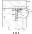
- Figure 3 depicts a cross section of an example of a new type of nozzle 200 positioned within the body, or housing, 410 of a servovalve after calibration.
- the body, or housing, 410 of the servovalve in which the nozzle is positioned is a hollow tube.
- fluid flow fuel or air
- the supply port(s) 290 is provided through the supply port(s) 290 and directed towards and out of the end 260 of the nozzle 200.
- the nozzle 200 is hollow and comprises an elongated cylindrical wall extending between a first end 250 and a second end 260.
- the second end 260 of the nozzle is the end which would be closest to the flapper, as described above, with reference to figure 1 .
- the first end 250 of the example shown in figures 3 to 5 has a first opening which is wider than an opening at the second end 260.
- the means for locking the nozzle 200 in position comprises a rotatable locking member 300.
- the locking member 300 may comprise a locking nut, as shown in figures 3 , 4 , 5 and 6 .
- the locking member 300 is provided within the nozzle 200 and has an outer circumferential surface that is ring shaped.
- the ring shaped locking member 300 has a first side 304 and an opposite second side 305 and a circumferential outer surface 302 extending there between.
- the circumferential outer surface 302 may have a thread 301 extending circumferentially around the outer surface 302 that is sized and shaped and configured to match and mate with a thread 201 that is provided on the circumferential inner surface 202 of the nozzle 200, as described later.
- the locking member 300 may therefore have an outer surface 302 and an outer circumference that is shaped and sized so as to be in contact with the inner surface 202 and inner circumference of the nozzle 200 so that the surfaces contact each other in use.
- the first end 250 of the nozzle is configured to receive the locking member 300 and the nozzle 200 can be described as having a first portion 207 extending from the first end 250 of the nozzle 200 and in the direction of the second end 260 of the nozzle.
- the first portion 207 of the nozzle comprises at least one cut-out section 203 extending from the first end 250 of the nozzle 200 in the direction of the second end 260 of the nozzle 200.
- the nozzle 200 may have a plurality of cut-out sections 203 at its first end 250 and in the first portion 207.
- Each cut-out section 203 corresponds to an area of the first portion 207 wherein a section of the nozzle body has been cut away and removed leaving a recess 203 in the nozzle.
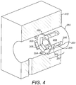
- the nozzle 200 comprises six cut-out sections 203, however, any number of cut-out sections 203 may be provided. Nozzle body wall sections 204 are therefore provided between these cut-out sections so that the cut-out sections 203 form a plurality of recesses 203 in the nozzle body wall, extending from its first end 250 and in the direction of the second end 260.
- the cut-out sections 203 comprise a longitudinal shape extending axially in the direction of the nozzle second end 260.
- the corresponding nozzle wall sections 204 are therefore also longitudinal in shape and extend axially in the direction of the nozzle second end 260.
- the nozzle's first end 250 comprises six longitudinal wall sections 204 extending from the nozzle first end 250 in the direction of its second end 260, in between six longitudinal cut out sections 203, however, these recesses 203 and nozzle body wall sections 204 there between may be any shape or in any number.
- the presence of these cut-out sections 203 and respective wall sections 204 provided between each cut out section 203 results in an increase in the compliance of the nozzle 200 and so the locking member 300 can therefore be more easily inserted into the first end 250 of the nozzle and can also be screwed in within the nozzle 200 deeper than if the nozzle did not have any cut out sections 203.
- cut-out sections 203 also provide a part of an interlocking means, as described below, which allow the nozzle to be interlocked and attached to a nozzle anti-rotation means 501, described later, to thereby prevent the nozzle 200 from rotating when torque is applied to the locking member 300.
- the nozzle 200 further comprises a second portion 206 extending from this first portion 207 in the direction of the nozzle second end 260, wherein the second portion 206 comprises a solid tubular shape with a circumferentially extending wall.
- This second portion 206 of the nozzle 200 may result in a press-fit seal between the external surface 205 of the nozzle 200 and the inner surface 402 of the body 410 in which it is positioned, as described below.
- the thread 201 provided on the inner surface 202 of the nozzle 200 and the corresponding thread 301 provided on the outer surface 302 of the locking member 300 may both further be tapered; however, this is not a necessity and in some examples, the thread 201, 301 may not be tapered.
- Providing a tapered thread on both the nozzle 200 and locking member 300 may also help to improve the ease with which the locking member 300 is inserted into and within the nozzle and further may improve the press-fit during the screwing in of the locking member 300.
- the dimensions and shapes of the nozzle 200 and the locking member 300 may also themselves be tapered.
- An example of a system wherein the nozzle 200 has an inner surface 202 that is tapered and wherein the locking member 300 has an outer surface that is tapered is shown in figure 3 .
- the outer surface 302 of the locking member 300 may be tapered so that the external diameter of the locking member 300 decreases in the direction of the locking member's second side 305 (i.e. away from the first side 304) from a first diameter D3 to a second diameter D4, the taper being at a first angle.
- the inner surface 202 of the nozzle may also be tapered so that the internal diameter of the nozzle 200 decreases in the direction of the second end 260 (i.e. away from the first end 250 and the cut-out sections 203 of the nozzle 200) from a first diameter D1 to a second diameter D2 at a second angle.
- These first and second taper angles may match and be equal so that as the locking member 300 is rotated, the second side 305 of the locking member is moved axially in the direction of the nozzle second end 260 via the correspondingly shaped surfaces and threads having matching tapering angles.
- This tapering of the corresponding surfaces in this direction also means that as the locking member is moved further within the nozzle in the direction of the second end of the nozzle, the screw becomes tighter and tighter within the nozzle.
- Figure 4 depicts a perspective view of the nozzle 200 positioned in the housing 410, (with part of the housing 410 cut away to show the nozzle 200), with the locking member 300 in place.
- Figure 5 depicts a means 500 for positioning and locking the nozzle 200 in place within the body 410 of the servovalve.
- This means 500 for positioning and locking the nozzle 200 in place may comprise means 502 for screwing the locking member 300 into place within the nozzle 200.
- Figure 5 shows how the locking nut 300 may be screwed inside the nozzle 200.
- the means 500 for positioning and locking the nozzle 200 in place may further comprise means 501 for preventing rotation of the nozzle 200 when the locking member 300 is screwed into and within the nozzle 200.
- the means for preventing rotation of the nozzle 200 as it is being fixed in place may comprise a nozzle anti-rotation means 501 (at least part of which may be external to the housing during calibration of the nozzle). This may be provided to prevent any possible rotation of the nozzle 200 as the locking member 300 is screwed into place within the nozzle 200.
- the first end 580 of the anti-rotation member 501 may be fixed so as to thereby prevent rotation of the nozzle 200 within the body 410, whilst still enabling torque to be provided to the locking member 300.
- the nozzle anti-rotation means 501 may comprise a hollow tube having a first end 580 and a second end 590.
- the tube may comprise a first section 581 extending from the first end 580 in the direction of the second end 590 and a second section 591 extending from this first section 581 to the second end 590 of the tube 501.
- the second section 591 of the tube 501 may comprise at least one cut-out section 593, or recess formed in the tube as shown in figure 7 .
- the second section 591 of the tube 501 therefore comprises a shape and structure that is the same as or at least very similar to the first section 207 of the nozzle 203 that comprises cut-out sections 203.
- the circumferential widths W1 of the cut-out sections 203 of the nozzle correspond to the circumferential widths W2 of the wall sections 594 of the tube 501 between the recesses 593 and the circumferential widths W3 of the cut-out sections 593 of the tube correspond to the circumferential widths W4 of the wall sections 204 of the nozzle between the recesses 203. Due to this, the longitudinal wall sections 204 of the nozzle 200 slot into place perfectly within the recesses 593 of the tube 501 and vice versa to interlock the nozzle 200 to the tube 501 as shown in figure 8 .
- the relative axial lengths L1 of the recesses 203 of the nozzle 200 are not so important in relation to the lengths L2 of the protruding wall sections 594 of the tube 501 (see figure 8 where the recesses are longer than the nozzle protruding sections), however, the relative widths W1, W3 of the recesses 203, 593 and widths W2, W4 of the protruding wall sections 204, 594 should be similar enough that they result in the end 590 of the anti-rotation means 501 interlocking with the first end 250 of the nozzle. In other words, they must contact each other to provide the interlocking of the nozzle 200 with the nozzle anti-rotation tube 501.
- the second end 590 tube 501 is connected to the first end 250 of the nozzle 200 via the interlocking means, which in the examples described herein comprises interlocking of the recesses 203, 593.
- interlocking/connecting means may also be used.
- the nozzle 200 is then inserted into the body 410 of the servovalve and when the nozzle is in the correct position within the servovalve body 410, the first end 580 of the tube 501 (which remains external to the body 410) is fixed into position. This may be achieved by any means, one example of such being fixed in position using a clamp.
- the nozzle 200 may then be locked into place via the use of a second rod 502 which comprises a first end 503 and a second end 504 with a longitudinal body 505 extending there between.
- the second end 506 of the rod 502 is connected to the locking member 300 and both may then be inserted into the hollow of the anti-rotation tube 501 so that the first end of the rod 502 is positioned externally to the housing 410 and protruding out from the first end 580 of the anti-rotation tube 501 as shown in figure 5 .
- the longitudinal body 505 of the rod 502 is positioned internally within the tube 501, and allows the user (via rotation of the protruding first end 503 of the rod 502) to provide torque to the locking member 300, to screw the locking member within the nozzle 200.
- Figure 6 depicts the same features as figure 5 , but with the nozzle anti-rotation tube 501 removed, so as to allow the internal features of the means 500 for calibrating (i.e. positioning and locking in place) the nozzle 200 to be seen.
- the second end 504 of the rod 502 is sized and shaped so as to contact the inner surface 306 of the ring-shaped locking member 300. Torque is then applied to the rod 502 at its first end 503 by the user.
- the first end 503 of the rod 502 may comprise further means 506 for facilitating the rotation of the rod 502.
- the means 506 for facilitating the rotation of the internal rod 502 may comprise a bolt 506 having six (or indeed any number of) sides, which can be rotated with the use of a corresponding Allen key or with a spanner or other such griping means.
- the rod 502 itself may simply be an Allen key, the outer surface of which may match the inner surface of the locking member 300.
- Known nozzles are usually centerless grinded and the hole in center of the body of the nozzle is burnished. With the new nozzles described herein, it is easy to manufacture these nozzles with cut-out sections via the use of milling, for example.
- the new nozzles 200, systems and methods described herein minimize axial forces as only torque is used to generate the press fit. This is a great improvement on other methods wherein axial forces are used to produce the press fit, as the use of axial forces can result in the nozzle being moved into an incorrect position.
- the nozzle can easily be removed simply by unscrewing the locking member 300.
- the resulting connection nozzle housing 410 in which the nozzle 200 is positioned will also be more resistant to thermal cycles as the locking member 300 may be made from the same material as the housing 410.
- the nozzle 200 may in some examples be made from a different material to the locking member 300 and/or the housing 410 and may be more deformable compared to known nozzles due to the presence of the cut-out sections 203.
Landscapes
- Engineering & Computer Science (AREA)
- General Engineering & Computer Science (AREA)
- Mechanical Engineering (AREA)
- Physics & Mathematics (AREA)
- Fluid Mechanics (AREA)
- Fuel-Injection Apparatus (AREA)
- Nozzles (AREA)
Claims (15)
- System zum Sichern einer Düse (200) an einer Stelle innerhalb eines Körpers (410), wobei der Körper (410) eine zylindrische Bohrung aufweist, die eine innere Fläche (402) definiert, wobei das System Folgendes umfasst:
die Düse (200), wobei die Düse (200) eine röhrenförmige Form aufweist, die sich zwischen einem ersten Ende (250) und einem zweiten Ende (260) mit einer äußeren zylindrischen Fläche (205) und einer inneren Fläche (202) erstreckt, dadurch gekennzeichnet, dass die innere Fläche (202) ein Gewinde (201) umfasst und das System ferner Folgendes umfasst:ein Sicherungselement (300); wobei das Sicherungselement (300) innerhalb der Düse (200) bereitgestellt ist und eine äußere umlaufende Fläche (302) mit einem Gewinde (301) umfasst, das dem Gewinde (201) der inneren Fläche (202) der Düse (200) entspricht;und Mittel (502) zum Bereitstellen von Drehmoment an das Sicherungselement (300), um das Sicherungselement (300) über die Gewindeflächen (202, 301) axial in die und innerhalb der Düse (200) zu schrauben und die äußere zylindrische Fläche (205) der Düse (200) in eine passgenaue Anordnung mit der inneren Fläche (402) der zylindrischen Bohrung des Körpers (410) radial auszudehnen. - System nach Anspruch 1, wobei
das erste Ende (250) der Düse dazu konfiguriert ist, das Sicherungselement (300) aufzunehmen,
und wobei die Düse (200) ferner einen ersten Abschnitt (207) umfasst, der sich von dem ersten Ende (250) und in die Richtung des zweiten Endes (260) erstreckt, wobei der erste Abschnitt (207) eine Vielzahl von ausgeschnittenen Bereichen (203) umfasst, die mit Wandbereichen (204) um seinen Umfang, die zwischen den ausgeschnittenen Bereichen (203) bereitgestellt sind, bereitgestellt ist, wobei sich die ausgeschnittenen Bereiche (230) von dem ersten Ende (250) der Düse (200) in die Richtung des zweiten Endes (260) der Düse (200) erstrecken. - System nach einem der vorstehenden Ansprüche, wobei die Düse (200) einen inneren Durchmesser aufweist, der zwischen dem ersten Ende (250) und dem zweiten Ende (260) abnimmt.
- System nach einem der vorstehenden Ansprüche, wobei das Sicherungselement (300) ringförmig mit einer ersten Seite (304) und einer zweiten Seite (305) ist, wobei sich eine umlaufende äußere Fläche zwischen der ersten und der zweiten Seite (304, 305) erstreckt und wobei der äußere Durchmesser (D4, D3) des ringförmigen Sicherungselements (300) zwischen der ersten Seite (304) und der zweiten Seite (305) abnimmt, um eine verjüngte äußere Fläche bereitzustellen, die sich mit einem ersten Winkel zwischen der ersten Seite (304) und der zweiten Seite (305) verjüngt.
- System nach Anspruch 4, wobei die Düse einen inneren Durchmesser aufweist, der zwischen dem ersten Ende (250) und dem zweiten Ende (260) abnimmt, um eine verjüngte innere Fläche bereitzustellen, die sich mit einem zweiten Winkel zwischen dem ersten Ende (250) und dem zweiten Ende (260) verjüngt, und wobei das erste Ende (250) der Düse dazu konfiguriert ist, das zweite Ende (305) des Sicherungselements aufzunehmen, und wobei der erste Winkel und der zweite Winkel gleich sind.
- System nach einem der vorstehenden Ansprüche, ferner Mittel (502) zum Anwenden von Drehmoment an das Sicherungselement (300) durch Rotieren des Sicherungselements (300) entlang der Gewindeflächen (201, 301) umfassend, um das Sicherungselement (300) axial in die Richtung des zweiten Endes (260) der Düse zu bewegen.
- System nach einem der vorstehenden Ansprüche, ferner Mittel (501) zum Verhindern von Rotation der Düse (200) innerhalb des Körpers (410), wenn das Drehmoment an das Sicherungselement (300) angewandt wird, umfassend.
- System nach Anspruch 7, wobei die Mittel (501) zum Verhindern von Rotation der Düse (200) innerhalb des Körpers (410) eine Röhre (501) umfassen, die sich von einem ersten Ende (580) zu einem zweiten Ende (590) erstreckt, wobei das zweite Ende (590) der Anti-Rotationsröhre (501) Mittel zum Ineinandersichern des zweiten Endes der Röhre (501) mit dem ersten Ende (250) der Düse (200) umfasst und an dem ersten Ende (580) der Röhre Mittel zum Positionsfixieren der Röhre (501), um Rotation der Röhre (501) zu verhindern, umfasst.
- System nach Anspruch 8, wobei die Mittel zum Ineinandersichern mindestens einen ausgeschnittenen Bereich (594) an dem zweiten Ende (590) der Anti-Rotationsröhre (501) und mindestens einen ausgeschnittenen Bereich (503) an dem ersten Ende (250) der Düse (200) umfassen, wobei die ausgeschnittenen Bereiche eine Form und eine Größe aufweisen, um es den zwei Enden (590, 250) zu ermöglichen, sich zusammenzufügen und ineinander zu sichern.
- Verfahren zum Sichern einer Düse (200) in Position innerhalb eines Körpers (410), wobei der Körper (410) eine zylindrische Bohrung aufweist, die eine innere Fläche (402) definiert, wobei das Verfahren Folgendes umfasst:
Positionieren der Düse (200) innerhalb der zylindrischen Bohrung des Körpers (410), wobei die Düse (200) eine röhrenförmige Form aufweist, die sich zwischen einem ersten Ende (250) und einem zweiten Ende (260) mit einer äußeren zylindrischen Fläche (205) und einer inneren Fläche (202) erstreckt, wobei die innere Fläche (202) ein Gewinde (201) umfasst, und ein Sicherungselement (300) innerhalb der Düse (200) bereitstellt, wobei das Sicherungselement (300) eine äußere umlaufende Fläche (302) mit einem Gewinde (301) umfasst, das dem Gewinde (201) der inneren Fläche (202) der Düse (200) entspricht, und wobei das Verfahren ferner Folgendes umfasst:Bereitstellen von Drehmoment an das Sicherungselement (300), um das Sicherungselement (300) über die Gewindeflächen (202, 301) axial in die undinnerhalb der Düse (200) in die Richtung des zweiten Endes (260) der Düse zu schrauben und die äußere zylindrische Fläche (205) der Düse (200) in eine passgenaue Anordnung mit der inneren Fläche (402) der zylindrischen Bohrung des Körpers (410) radial auszudehnen. - Verfahren nach Anspruch 10, wobei die äußere Fläche des Sicherungselements (300) ringförmig mit einer ersten Seite (304) und einer zweiten Seite (305) ist und das Verfahren ferner den Schritt des Verjüngens der äußeren Fläche des ringförmigen Sicherungselements (300) mit einem ersten Winkel umfasst, sodass der äußere Durchmesser des Sicherungselements (300) zwischen der ersten Seite (304) und der zweiten Seite (305) mit dem ersten Winkel abnimmt, und ferner den Schritt des Verjüngens der inneren Fläche der Düse (200) umfasst, sodass der innere Durchmesser der Düse (200) zwischen dem ersten Ende (250) und dem zweiten Ende (260) abnimmt, um eine verjüngte innere Fläche bereitzustellen, die sich mit einem zweiten Winkel zwischen dem ersten Ende (250) und dem zweiten Ende (260) verjüngt, wobei der erste Winkel und der zweite Winkel gleich sind.
- Verfahren nach einem der Ansprüche 10 oder 11, ferner den Schritt des Positionierens der Düse (200) innerhalb der zylindrischen Bohrung des Körpers (410) durch Bereitstellen eines Anti-Rotationselements (501) der Düse mit einem ersten Ende (580) und einem zweiten Ende (590) umfassend und, vor dem Schritt des Positionierens der Düse an einer Stelle innerhalb der zylindrischen Bohrung des Körpers (410), ferner den Schritt des Verbindens des zweiten Endes (580) des Anti-Rotationselements (501) der Düse mit dem ersten Ende (250) der Düse (200) und des Einsetzens der Düse (200) in die zylindrische Bohrung des Körpers (410) durch axiales Bewegen des Anti-Rotationselements (501) und der Düse (200) innerhalb der zylindrischen Bohrung des Körpers (410) umfassend.
- Verfahren nach Anspruch 12, ferner den Schritt des Positionsfixierens des ersten Endes (580) des Anti-Rotationselements (501) und damit Verhindern von Rotation der Düse (200) innerhalb des Körpers (410), während Drehmoment an das Sicherungselement (300) bereitgestellt wird, umfassend.
- Verfahren nach Anspruch 12 oder 13, wobei das Anti-Rotationselement (501) eine Röhre (501) umfasst, die sich von einem ersten Ende (580) zu einem zweiten Ende (590) erstreckt, wobei das zweite Ende (590) der Anti-Rotationsröhre (501) Mittel zum Ineinandersichern des zweiten Endes der Röhre (501) mit dem ersten Ende (250) der Düse (200) umfasst.
- Verfahren nach Anspruch 14, wobei die Mittel zum Ineinandersichern mindestens einen ausgeschnittenen Bereich (594) an dem zweiten Ende (590) der Anti-Rotationsröhre (501) und mindestens einen ausgeschnittenen Bereich (503) an dem ersten Ende (250) der Düse (200) umfassen, wobei die ausgeschnittenen Bereiche eine Form und eine Größe aufweisen, um es den zwei Enden (590, 250) zu ermöglichen, sich zusammenzufügen und ineinander zu sichern.
Priority Applications (2)
| Application Number | Priority Date | Filing Date | Title |
|---|---|---|---|
| EP16461555.1A EP3293401B1 (de) | 2016-09-12 | 2016-09-12 | Düse mit sicherungsmutter |
| US15/647,581 US10927859B2 (en) | 2016-09-12 | 2017-07-12 | Nozzle with locking nut |
Applications Claiming Priority (1)
| Application Number | Priority Date | Filing Date | Title |
|---|---|---|---|
| EP16461555.1A EP3293401B1 (de) | 2016-09-12 | 2016-09-12 | Düse mit sicherungsmutter |
Publications (2)
| Publication Number | Publication Date |
|---|---|
| EP3293401A1 EP3293401A1 (de) | 2018-03-14 |
| EP3293401B1 true EP3293401B1 (de) | 2019-07-24 |
Family
ID=56943460
Family Applications (1)
| Application Number | Title | Priority Date | Filing Date |
|---|---|---|---|
| EP16461555.1A Active EP3293401B1 (de) | 2016-09-12 | 2016-09-12 | Düse mit sicherungsmutter |
Country Status (2)
| Country | Link |
|---|---|
| US (1) | US10927859B2 (de) |
| EP (1) | EP3293401B1 (de) |
Family Cites Families (16)
| Publication number | Priority date | Publication date | Assignee | Title |
|---|---|---|---|---|
| US683082A (en) * | 1900-06-30 | 1901-09-24 | John C Summerer | Espansion-bolt. |
| GB845109A (en) * | 1956-10-08 | 1960-08-17 | Moog Servocontrols Inc | Improvements in or relating to electrically operated servo valves |
| NL242603A (de) * | 1959-06-04 | 1900-01-01 | ||
| US3202034A (en) * | 1963-01-18 | 1965-08-24 | John J Korenchan | Bolt anchorage with loosening preventing means |
| US3415283A (en) * | 1964-09-08 | 1968-12-10 | Servotronics | Torque motor |
| GB1100149A (en) * | 1965-05-05 | 1968-01-24 | Moog Inc | Moving coil electrohydraulic servovalve |
| US3556150A (en) * | 1969-05-12 | 1971-01-19 | Borg Warner | Electro hydraulic servovalve |
| US4015505A (en) * | 1976-02-23 | 1977-04-05 | Illinois Tool Works Inc. | One sided fastener device |
| DE3630200A1 (de) * | 1986-09-04 | 1988-03-17 | Rexroth Mannesmann Gmbh | Hydraulisches servoventil |
| US5070898A (en) * | 1991-02-11 | 1991-12-10 | Hsc Controls Inc. | Metering valve |
| DE4311216A1 (de) * | 1993-04-05 | 1994-10-06 | Rexroth Mannesmann Gmbh | Verstellen einer Druckwaage bzw. des hydraulischen Verstärkers eines Servoventils mittels Disk-Translator |
| US6076797A (en) * | 1998-10-01 | 2000-06-20 | Schnautz; Kurt | Mold sealing plug |
| JP2001074162A (ja) * | 1999-09-01 | 2001-03-23 | Ebara Corp | 流体制御弁及びフィルタ付きプレート |
| US20020189674A1 (en) * | 2001-03-29 | 2002-12-19 | Meeder Ernest P. | Assembly and method of mounting a liquid delivery device utilizing expanding bushing |
| US20050089364A1 (en) * | 2003-10-24 | 2005-04-28 | Geib Randall R. | Mounting device |
| ITBZ20120026A1 (it) * | 2012-06-27 | 2013-12-28 | Enetec Srl | Tappo di espansione per tubi in plastica |
-
2016
- 2016-09-12 EP EP16461555.1A patent/EP3293401B1/de active Active
-
2017
- 2017-07-12 US US15/647,581 patent/US10927859B2/en active Active
Non-Patent Citations (1)
| Title |
|---|
| None * |
Also Published As
| Publication number | Publication date |
|---|---|
| EP3293401A1 (de) | 2018-03-14 |
| US20180073526A1 (en) | 2018-03-15 |
| US10927859B2 (en) | 2021-02-23 |
Similar Documents
| Publication | Publication Date | Title |
|---|---|---|
| US11253960B2 (en) | Nozzle with changeable press fit | |
| CN104471505B (zh) | 直动式螺线管致动器 | |
| US4010390A (en) | Electromagnetic actuator comprising a plunger core | |
| US20160290368A1 (en) | Servo valves | |
| EP3409987B1 (de) | Federabgedichtetes pneumatisches servoventil | |
| EP2947666A1 (de) | Elektromechanische magnetspule mit einem polteilausrichtungselement | |
| NZ200517A (en) | Variable gain servo controlled direction valve for hydraulic control system | |
| US20140361205A1 (en) | Setting Screw Connection for a Hydraulic Valve, and Hydraulic Valve | |
| US10753488B2 (en) | Three-way hydraulic valve with a floating bushing | |
| US10927859B2 (en) | Nozzle with locking nut | |
| JP2013007745A (ja) | データム調整を伴う誘導センサ | |
| US5653421A (en) | Fluid switch | |
| US7150445B2 (en) | Valve device having a long adjustment stroke | |
| EP3715643B1 (de) | Servoventil mit verbesserter abdichtung und verfahren zur herstellung davon | |
| EP3550179B1 (de) | Betätigungskolben mit verstellbaren anschläge | |
| CN105909587A (zh) | 电液伺服阀力反馈结构 | |
| WO2002093592A2 (de) | Magnetanordnung | |
| US11125339B2 (en) | Methods and assemblies for retaining an internal component of a valve within an external component thereof using a retention O-ring and groove geometry | |
| US20180346129A1 (en) | Pneumatic servo valve with adjustable metering members | |
| CN217539709U (zh) | 一种喷嘴挡板伺服阀的调整装置 | |
| EP0571128A1 (de) | Motor mit Temperaturkompensation | |
| CN105546175A (zh) | 一种四余度传感器与伺服阀阀体的连接结构和零位调节方法 | |
| US6933639B2 (en) | Method and configuration for driving a thrust body by a bidirectional linear solenoid drive | |
| KR101161802B1 (ko) | 유압서보밸브 튜닝시스템 | |
| EP3536978B1 (de) | Servoventil |
Legal Events
| Date | Code | Title | Description |
|---|---|---|---|
| PUAI | Public reference made under article 153(3) epc to a published international application that has entered the european phase |
Free format text: ORIGINAL CODE: 0009012 |
|
| STAA | Information on the status of an ep patent application or granted ep patent |
Free format text: STATUS: THE APPLICATION HAS BEEN PUBLISHED |
|
| AK | Designated contracting states |
Kind code of ref document: A1 Designated state(s): AL AT BE BG CH CY CZ DE DK EE ES FI FR GB GR HR HU IE IS IT LI LT LU LV MC MK MT NL NO PL PT RO RS SE SI SK SM TR |
|
| AX | Request for extension of the european patent |
Extension state: BA ME |
|
| STAA | Information on the status of an ep patent application or granted ep patent |
Free format text: STATUS: REQUEST FOR EXAMINATION WAS MADE |
|
| 17P | Request for examination filed |
Effective date: 20180913 |
|
| RBV | Designated contracting states (corrected) |
Designated state(s): AL AT BE BG CH CY CZ DE DK EE ES FI FR GB GR HR HU IE IS IT LI LT LU LV MC MK MT NL NO PL PT RO RS SE SI SK SM TR |
|
| REG | Reference to a national code |
Ref country code: DE Ref legal event code: R079 Ref document number: 602016017273 Country of ref document: DE Free format text: PREVIOUS MAIN CLASS: F15B0009070000 Ipc: F15B0013043000 |
|
| RIC1 | Information provided on ipc code assigned before grant |
Ipc: F15B 9/07 20060101ALI20181218BHEP Ipc: F15B 13/043 20060101AFI20181218BHEP Ipc: F15B 19/00 20060101ALI20181218BHEP Ipc: F15B 9/06 20060101ALI20181218BHEP |
|
| GRAP | Despatch of communication of intention to grant a patent |
Free format text: ORIGINAL CODE: EPIDOSNIGR1 |
|
| STAA | Information on the status of an ep patent application or granted ep patent |
Free format text: STATUS: GRANT OF PATENT IS INTENDED |
|
| INTG | Intention to grant announced |
Effective date: 20190129 |
|
| GRAS | Grant fee paid |
Free format text: ORIGINAL CODE: EPIDOSNIGR3 |
|
| GRAA | (expected) grant |
Free format text: ORIGINAL CODE: 0009210 |
|
| STAA | Information on the status of an ep patent application or granted ep patent |
Free format text: STATUS: THE PATENT HAS BEEN GRANTED |
|
| AK | Designated contracting states |
Kind code of ref document: B1 Designated state(s): AL AT BE BG CH CY CZ DE DK EE ES FI FR GB GR HR HU IE IS IT LI LT LU LV MC MK MT NL NO PL PT RO RS SE SI SK SM TR |
|
| REG | Reference to a national code |
Ref country code: GB Ref legal event code: FG4D |
|
| REG | Reference to a national code |
Ref country code: CH Ref legal event code: EP |
|
| REG | Reference to a national code |
Ref country code: DE Ref legal event code: R096 Ref document number: 602016017273 Country of ref document: DE |
|
| REG | Reference to a national code |
Ref country code: AT Ref legal event code: REF Ref document number: 1158517 Country of ref document: AT Kind code of ref document: T Effective date: 20190815 |
|
| REG | Reference to a national code |
Ref country code: IE Ref legal event code: FG4D |
|
| REG | Reference to a national code |
Ref country code: NL Ref legal event code: MP Effective date: 20190724 |
|
| REG | Reference to a national code |
Ref country code: LT Ref legal event code: MG4D |
|
| REG | Reference to a national code |
Ref country code: AT Ref legal event code: MK05 Ref document number: 1158517 Country of ref document: AT Kind code of ref document: T Effective date: 20190724 |
|
| PG25 | Lapsed in a contracting state [announced via postgrant information from national office to epo] |
Ref country code: NO Free format text: LAPSE BECAUSE OF FAILURE TO SUBMIT A TRANSLATION OF THE DESCRIPTION OR TO PAY THE FEE WITHIN THE PRESCRIBED TIME-LIMIT Effective date: 20191024 Ref country code: SE Free format text: LAPSE BECAUSE OF FAILURE TO SUBMIT A TRANSLATION OF THE DESCRIPTION OR TO PAY THE FEE WITHIN THE PRESCRIBED TIME-LIMIT Effective date: 20190724 Ref country code: AT Free format text: LAPSE BECAUSE OF FAILURE TO SUBMIT A TRANSLATION OF THE DESCRIPTION OR TO PAY THE FEE WITHIN THE PRESCRIBED TIME-LIMIT Effective date: 20190724 Ref country code: FI Free format text: LAPSE BECAUSE OF FAILURE TO SUBMIT A TRANSLATION OF THE DESCRIPTION OR TO PAY THE FEE WITHIN THE PRESCRIBED TIME-LIMIT Effective date: 20190724 Ref country code: PT Free format text: LAPSE BECAUSE OF FAILURE TO SUBMIT A TRANSLATION OF THE DESCRIPTION OR TO PAY THE FEE WITHIN THE PRESCRIBED TIME-LIMIT Effective date: 20191125 Ref country code: HR Free format text: LAPSE BECAUSE OF FAILURE TO SUBMIT A TRANSLATION OF THE DESCRIPTION OR TO PAY THE FEE WITHIN THE PRESCRIBED TIME-LIMIT Effective date: 20190724 Ref country code: NL Free format text: LAPSE BECAUSE OF FAILURE TO SUBMIT A TRANSLATION OF THE DESCRIPTION OR TO PAY THE FEE WITHIN THE PRESCRIBED TIME-LIMIT Effective date: 20190724 Ref country code: BG Free format text: LAPSE BECAUSE OF FAILURE TO SUBMIT A TRANSLATION OF THE DESCRIPTION OR TO PAY THE FEE WITHIN THE PRESCRIBED TIME-LIMIT Effective date: 20191024 Ref country code: LT Free format text: LAPSE BECAUSE OF FAILURE TO SUBMIT A TRANSLATION OF THE DESCRIPTION OR TO PAY THE FEE WITHIN THE PRESCRIBED TIME-LIMIT Effective date: 20190724 |
|
| PG25 | Lapsed in a contracting state [announced via postgrant information from national office to epo] |
Ref country code: ES Free format text: LAPSE BECAUSE OF FAILURE TO SUBMIT A TRANSLATION OF THE DESCRIPTION OR TO PAY THE FEE WITHIN THE PRESCRIBED TIME-LIMIT Effective date: 20190724 Ref country code: AL Free format text: LAPSE BECAUSE OF FAILURE TO SUBMIT A TRANSLATION OF THE DESCRIPTION OR TO PAY THE FEE WITHIN THE PRESCRIBED TIME-LIMIT Effective date: 20190724 Ref country code: GR Free format text: LAPSE BECAUSE OF FAILURE TO SUBMIT A TRANSLATION OF THE DESCRIPTION OR TO PAY THE FEE WITHIN THE PRESCRIBED TIME-LIMIT Effective date: 20191025 Ref country code: LV Free format text: LAPSE BECAUSE OF FAILURE TO SUBMIT A TRANSLATION OF THE DESCRIPTION OR TO PAY THE FEE WITHIN THE PRESCRIBED TIME-LIMIT Effective date: 20190724 Ref country code: RS Free format text: LAPSE BECAUSE OF FAILURE TO SUBMIT A TRANSLATION OF THE DESCRIPTION OR TO PAY THE FEE WITHIN THE PRESCRIBED TIME-LIMIT Effective date: 20190724 Ref country code: IS Free format text: LAPSE BECAUSE OF FAILURE TO SUBMIT A TRANSLATION OF THE DESCRIPTION OR TO PAY THE FEE WITHIN THE PRESCRIBED TIME-LIMIT Effective date: 20191124 |
|
| PG25 | Lapsed in a contracting state [announced via postgrant information from national office to epo] |
Ref country code: TR Free format text: LAPSE BECAUSE OF FAILURE TO SUBMIT A TRANSLATION OF THE DESCRIPTION OR TO PAY THE FEE WITHIN THE PRESCRIBED TIME-LIMIT Effective date: 20190724 |
|
| PG25 | Lapsed in a contracting state [announced via postgrant information from national office to epo] |
Ref country code: PL Free format text: LAPSE BECAUSE OF FAILURE TO SUBMIT A TRANSLATION OF THE DESCRIPTION OR TO PAY THE FEE WITHIN THE PRESCRIBED TIME-LIMIT Effective date: 20190724 Ref country code: RO Free format text: LAPSE BECAUSE OF FAILURE TO SUBMIT A TRANSLATION OF THE DESCRIPTION OR TO PAY THE FEE WITHIN THE PRESCRIBED TIME-LIMIT Effective date: 20190724 Ref country code: IT Free format text: LAPSE BECAUSE OF FAILURE TO SUBMIT A TRANSLATION OF THE DESCRIPTION OR TO PAY THE FEE WITHIN THE PRESCRIBED TIME-LIMIT Effective date: 20190724 Ref country code: DK Free format text: LAPSE BECAUSE OF FAILURE TO SUBMIT A TRANSLATION OF THE DESCRIPTION OR TO PAY THE FEE WITHIN THE PRESCRIBED TIME-LIMIT Effective date: 20190724 Ref country code: EE Free format text: LAPSE BECAUSE OF FAILURE TO SUBMIT A TRANSLATION OF THE DESCRIPTION OR TO PAY THE FEE WITHIN THE PRESCRIBED TIME-LIMIT Effective date: 20190724 |
|
| PG25 | Lapsed in a contracting state [announced via postgrant information from national office to epo] |
Ref country code: CZ Free format text: LAPSE BECAUSE OF FAILURE TO SUBMIT A TRANSLATION OF THE DESCRIPTION OR TO PAY THE FEE WITHIN THE PRESCRIBED TIME-LIMIT Effective date: 20190724 Ref country code: SM Free format text: LAPSE BECAUSE OF FAILURE TO SUBMIT A TRANSLATION OF THE DESCRIPTION OR TO PAY THE FEE WITHIN THE PRESCRIBED TIME-LIMIT Effective date: 20190724 Ref country code: IS Free format text: LAPSE BECAUSE OF FAILURE TO SUBMIT A TRANSLATION OF THE DESCRIPTION OR TO PAY THE FEE WITHIN THE PRESCRIBED TIME-LIMIT Effective date: 20200224 Ref country code: SK Free format text: LAPSE BECAUSE OF FAILURE TO SUBMIT A TRANSLATION OF THE DESCRIPTION OR TO PAY THE FEE WITHIN THE PRESCRIBED TIME-LIMIT Effective date: 20190724 Ref country code: MC Free format text: LAPSE BECAUSE OF FAILURE TO SUBMIT A TRANSLATION OF THE DESCRIPTION OR TO PAY THE FEE WITHIN THE PRESCRIBED TIME-LIMIT Effective date: 20190724 |
|
| REG | Reference to a national code |
Ref country code: CH Ref legal event code: PL |
|
| REG | Reference to a national code |
Ref country code: DE Ref legal event code: R097 Ref document number: 602016017273 Country of ref document: DE |
|
| PLBE | No opposition filed within time limit |
Free format text: ORIGINAL CODE: 0009261 |
|
| STAA | Information on the status of an ep patent application or granted ep patent |
Free format text: STATUS: NO OPPOSITION FILED WITHIN TIME LIMIT |
|
| PG2D | Information on lapse in contracting state deleted |
Ref country code: IS |
|
| PG25 | Lapsed in a contracting state [announced via postgrant information from national office to epo] |
Ref country code: IE Free format text: LAPSE BECAUSE OF NON-PAYMENT OF DUE FEES Effective date: 20190912 Ref country code: LU Free format text: LAPSE BECAUSE OF NON-PAYMENT OF DUE FEES Effective date: 20190912 Ref country code: CH Free format text: LAPSE BECAUSE OF NON-PAYMENT OF DUE FEES Effective date: 20190930 Ref country code: LI Free format text: LAPSE BECAUSE OF NON-PAYMENT OF DUE FEES Effective date: 20190930 |
|
| REG | Reference to a national code |
Ref country code: BE Ref legal event code: MM Effective date: 20190930 |
|
| 26N | No opposition filed |
Effective date: 20200603 |
|
| PG25 | Lapsed in a contracting state [announced via postgrant information from national office to epo] |
Ref country code: BE Free format text: LAPSE BECAUSE OF NON-PAYMENT OF DUE FEES Effective date: 20190930 Ref country code: SI Free format text: LAPSE BECAUSE OF FAILURE TO SUBMIT A TRANSLATION OF THE DESCRIPTION OR TO PAY THE FEE WITHIN THE PRESCRIBED TIME-LIMIT Effective date: 20190724 |
|
| PG25 | Lapsed in a contracting state [announced via postgrant information from national office to epo] |
Ref country code: CY Free format text: LAPSE BECAUSE OF FAILURE TO SUBMIT A TRANSLATION OF THE DESCRIPTION OR TO PAY THE FEE WITHIN THE PRESCRIBED TIME-LIMIT Effective date: 20190724 |
|
| PG25 | Lapsed in a contracting state [announced via postgrant information from national office to epo] |
Ref country code: MT Free format text: LAPSE BECAUSE OF FAILURE TO SUBMIT A TRANSLATION OF THE DESCRIPTION OR TO PAY THE FEE WITHIN THE PRESCRIBED TIME-LIMIT Effective date: 20190724 Ref country code: HU Free format text: LAPSE BECAUSE OF FAILURE TO SUBMIT A TRANSLATION OF THE DESCRIPTION OR TO PAY THE FEE WITHIN THE PRESCRIBED TIME-LIMIT; INVALID AB INITIO Effective date: 20160912 |
|
| PG25 | Lapsed in a contracting state [announced via postgrant information from national office to epo] |
Ref country code: MK Free format text: LAPSE BECAUSE OF FAILURE TO SUBMIT A TRANSLATION OF THE DESCRIPTION OR TO PAY THE FEE WITHIN THE PRESCRIBED TIME-LIMIT Effective date: 20190724 |
|
| P01 | Opt-out of the competence of the unified patent court (upc) registered |
Effective date: 20230522 |
|
| PGFP | Annual fee paid to national office [announced via postgrant information from national office to epo] |
Ref country code: DE Payment date: 20250820 Year of fee payment: 10 |
|
| PGFP | Annual fee paid to national office [announced via postgrant information from national office to epo] |
Ref country code: GB Payment date: 20250822 Year of fee payment: 10 |
|
| PGFP | Annual fee paid to national office [announced via postgrant information from national office to epo] |
Ref country code: FR Payment date: 20250820 Year of fee payment: 10 |