EP3293404A1 - Pastille plastique et systeme comprenant une telle pastille plastique - Google Patents
Pastille plastique et systeme comprenant une telle pastille plastique Download PDFInfo
- Publication number
- EP3293404A1 EP3293404A1 EP16188266.7A EP16188266A EP3293404A1 EP 3293404 A1 EP3293404 A1 EP 3293404A1 EP 16188266 A EP16188266 A EP 16188266A EP 3293404 A1 EP3293404 A1 EP 3293404A1
- Authority
- EP
- European Patent Office
- Prior art keywords
- sealing ring
- plastic cap
- sheet
- flange
- longitudinal axis
- Prior art date
- Legal status (The legal status is an assumption and is not a legal conclusion. Google has not performed a legal analysis and makes no representation as to the accuracy of the status listed.)
- Granted
Links
Images


Classifications
-
- F—MECHANICAL ENGINEERING; LIGHTING; HEATING; WEAPONS; BLASTING
- F16—ENGINEERING ELEMENTS AND UNITS; GENERAL MEASURES FOR PRODUCING AND MAINTAINING EFFECTIVE FUNCTIONING OF MACHINES OR INSTALLATIONS; THERMAL INSULATION IN GENERAL
- F16B—DEVICES FOR FASTENING OR SECURING CONSTRUCTIONAL ELEMENTS OR MACHINE PARTS TOGETHER, e.g. NAILS, BOLTS, CIRCLIPS, CLAMPS, CLIPS OR WEDGES; JOINTS OR JOINTING
- F16B37/00—Nuts or like thread-engaging members
- F16B37/14—Cap nuts; Nut caps or bolt caps
-
- F—MECHANICAL ENGINEERING; LIGHTING; HEATING; WEAPONS; BLASTING
- F16—ENGINEERING ELEMENTS AND UNITS; GENERAL MEASURES FOR PRODUCING AND MAINTAINING EFFECTIVE FUNCTIONING OF MACHINES OR INSTALLATIONS; THERMAL INSULATION IN GENERAL
- F16B—DEVICES FOR FASTENING OR SECURING CONSTRUCTIONAL ELEMENTS OR MACHINE PARTS TOGETHER, e.g. NAILS, BOLTS, CIRCLIPS, CLAMPS, CLIPS OR WEDGES; JOINTS OR JOINTING
- F16B33/00—Features common to bolt and nut
- F16B33/004—Sealing; Insulation
-
- H—ELECTRICITY
- H01—ELECTRIC ELEMENTS
- H01R—ELECTRICALLY-CONDUCTIVE CONNECTIONS; STRUCTURAL ASSOCIATIONS OF A PLURALITY OF MUTUALLY-INSULATED ELECTRICAL CONNECTING ELEMENTS; COUPLING DEVICES; CURRENT COLLECTORS
- H01R13/00—Details of coupling devices of the kinds covered by groups H01R12/70 or H01R24/00 - H01R33/00
- H01R13/46—Bases; Cases
- H01R13/52—Dustproof, splashproof, drip-proof, waterproof, or flameproof cases
- H01R13/5213—Covers
-
- H—ELECTRICITY
- H01—ELECTRIC ELEMENTS
- H01R—ELECTRICALLY-CONDUCTIVE CONNECTIONS; STRUCTURAL ASSOCIATIONS OF A PLURALITY OF MUTUALLY-INSULATED ELECTRICAL CONNECTING ELEMENTS; COUPLING DEVICES; CURRENT COLLECTORS
- H01R4/00—Electrically-conductive connections between two or more conductive members in direct contact, i.e. touching one another; Means for effecting or maintaining such contact; Electrically-conductive connections having two or more spaced connecting locations for conductors and using contact members penetrating insulation
- H01R4/58—Electrically-conductive connections between two or more conductive members in direct contact, i.e. touching one another; Means for effecting or maintaining such contact; Electrically-conductive connections having two or more spaced connecting locations for conductors and using contact members penetrating insulation characterised by the form or material of the contacting members
- H01R4/64—Connections between or with conductive parts having primarily a non-electric function, e.g. frame, casing, rail
-
- F—MECHANICAL ENGINEERING; LIGHTING; HEATING; WEAPONS; BLASTING
- F16—ENGINEERING ELEMENTS AND UNITS; GENERAL MEASURES FOR PRODUCING AND MAINTAINING EFFECTIVE FUNCTIONING OF MACHINES OR INSTALLATIONS; THERMAL INSULATION IN GENERAL
- F16B—DEVICES FOR FASTENING OR SECURING CONSTRUCTIONAL ELEMENTS OR MACHINE PARTS TOGETHER, e.g. NAILS, BOLTS, CIRCLIPS, CLAMPS, CLIPS OR WEDGES; JOINTS OR JOINTING
- F16B37/00—Nuts or like thread-engaging members
- F16B37/08—Quickly-detachable or mountable nuts, e.g. consisting of two or more parts; Nuts movable along the bolt after tilting the nut
- F16B37/0807—Nuts engaged from the end of the bolt, e.g. axially slidable nuts
- F16B37/0842—Nuts engaged from the end of the bolt, e.g. axially slidable nuts fastened to the threaded bolt with snap-on-action, e.g. push-on nuts for stud bolts
Definitions
- a cap-shaped cover member which serves to protect the threaded shaft of a welded to a body welding stud by this is pressed onto the threaded shaft.
- the cover is formed as a hollow cylinder with a receiving opening for receiving the threaded shank of a threaded bolt, wherein the opposite side of the receiving opening is closed to form a cap shape.
- Bolt or Einpressbolzen be used in the automotive industry, and can be pressed into sheet metal parts with little effort.
- Such press-in pins joined in sheet metal parts serve, for example, in the manufacture of vehicle bodies to fasten further components to the threaded bolt.
- the document DE102014009410A1 discloses a method of joining a press-fit bolt to a preformed sheet metal part and a cover member for carrying out the method to solve this problem.
- the cover serves as a die when joining a press-in with a sheet metal part, and is pressed simultaneously with the preparation of this compound on the pin portion of the press-in.
- the cover is formed on the opening side with a radial flange, which has an elastically resilient sealing edge edge. By this elastically resilient sealing edge, the tightness is improved in the pressed onto the pin portion state of the cover, which seals axially on the plate.
- the sheet is stretched by leveling in the pressing process towards the bolt, and seals so from the flange down.
- the sheet is placed only in the assembly and then only undefined in the planar position and the springback after the pressing process further negatively affected, a total seal can not be ensured.
- the present invention is therefore an object of the invention to provide an improved cover, which preferably allows better tightness and better mounting flexibility. It is another object of the invention to provide an assembly with a plastic cap, a bolt and a sheet, which can be supplied to a liquid medium, without the bolt comes into contact with the liquid medium.
- the second sealing ring integral with the rest of the plastic cap, is easy to manufacture and can provide total tightness without additional steps. It allows a specific tightness around the recording. The position of the second sealing ring does not change the outer shape of the plastic cap, allowing easy integration into new or existing production lines.
- the second sealing ring and the first sealing ring are arranged concentrically to one another. This allows a rotational symmetry, in particular around the longitudinal axis.
- the first sealing ring is formed continuously.
- the second sealing ring is also formed continuously.
- the second sealing ring has a first surface and a second surface, wherein the first surface is parallel to the first Longitudinal axis extends, and wherein the second surface extends obliquely to the longitudinal axis.
- the first sealing ring has a first height along the longitudinal axis.
- the second sealing ring has a second height along the longitudinal axis. The first height is greater than the second height. This difference in height allows a better distribution of force.
- the first sealing ring extends radially outward from the longitudinal axis. The forces are better distributed during the pressing.
- the first sealing ring has two concentric sealing rings. The forces are better distributed during the pressing and improves the tightness.
- the plastic cap on a rib which projects into the receptacle.
- the rib makes it possible to produce a better holding force.
- the plastic cap has a ramp projecting from its outer circumferential surface. The ramp allows for better holding power.
- the receptacle is closed, and the main body extends along the longitudinal axis over the receptacle. This extension allows for improved engagement of the plastic cap.
- the tightness with the sheet is made by the two sealing rings.
- the geometry and position of the two sealing rings allow easy and safe sealing without additional resources. Such an arrangement allows a seal to be made undefined, also the sealing surface en anydem sheet metal, without soft components are necessary. The pressing and flattening of a support plate is still ensured.
- the sheet is an aluminum sheet.
- the second sealing ring is pressed against the surface of the sheet, that the second sealing ring is deformed by the surface of the sheet, wherein the second sealing ring has a first surface and a second surface, wherein the first surface in the direction of the first Sealing ring shows, and wherein the second surface is provided opposite the first surface and is in contact with the surface of the sheet.
- the sheet has a recess on the sheet opening circumference prior to the pressing of the bolt.
- the second sealing ring is opposite to the depression.
- the first sealing ring lies opposite a portion of the sheet that is without recess or bend.
- a plastic cap having a base body, which has a receptacle suitable for a screw with an opening, wherein the base body extends along a longitudinal axis between a first and a second portion, wherein the main body has an outer surface and a having inner surface, the inner surface facing towards the receptacle; and a flange disposed concentric with the longitudinal axis and having a first sealing ring disposed on the flange periphery, the flange being provided at the periphery of the opening against the first portion, the flange having first and second surfaces, the first surface facing the body the second surface is disposed opposite to the first surface, and wherein the first sealing ring protrudes from the second surface.
- the plastic cap has a rib projecting into the receptacle and a ramp projecting from its outer circumferential surface.
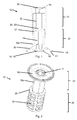
- the plastic cap 10 is essentially a cap-shaped cover.
- the plastic cap 10 has a base body 12.
- the main body is for example a cylindrical sleeve.
- the cylindrical sleeve has a cross-section that is not circular.
- the cylindrical sleeve has, for example, a polygonal cross section.
- the main body 12 extends along a longitudinal axis Xa.
- the main body 12 includes a receptacle 14. Die Pick-up 14 may have a rotational symmetry about the longitudinal axis Xa.
- the receptacle 14 has an opening 16 and is suitable for a screw.
- the receptacle 14 extends along the longitudinal axis Xa between a first portion 18 and a second portion 20.
- the opening 16 is formed on the first portion 18.
- the receptacle 14 has, for example, a circular cross-section.
- the main body 12 has a first region 22 which is substantially cylindrical and which comprises the receptacle 14.
- the first region 22 is closed by a cover 24.
- the lid 24 is formed on the second portion 20.
- the receptacle 14 is closed by the lid 24 and forms a blind hole.
- the receptacle 14 is circumferentially sealed.
- the first region 22 forms a nut.
- the outer surface Fa of the first region 22 has, for example, a hexagonal region, as in FIG Fig. 2 . Fig. 7 and Fig. 9 shown.
- a second region 26 may be connected to the first region 22.
- the plastic cap 10 no further second area.
- the second region 26 forms a hollow cylindrical sliding sleeve 28.
- the second region 26 extends along the longitudinal axis Xa between the second portion 20 and a third portion 30.
- the third portion 30 is opened.
- the second region 26 has an inner circumferential surface Mi and an outer circumferential surface Ma.
- the inner lateral surface Mi forms a second receptacle 32.
- the outer circumferential surface Ma is preferably formed with engagement features 34 as already in Fig. 2 . Fig. 3 . Fig. 6 . Fig. 7 . Fig. 8 and Fig. 9 shown.
- the engagement features 34 are notches, for example.
- the engagement features 34 may be regularly distributed over the outer circumferential surface Ma.
- the sliding sleeve 28 is integrally formed, for example separable. A predetermined breaking point can be provided between the sliding sleeve 28 and the first region.
- the sliding sleeve 28 has, for example, an inner diameter that is greater than or almost the same as the outer diameter of the first region 22. The sliding sleeve 28 can be pushed over the first region 22 under its pressure.
- a radially encircling flange 36 is integrally formed on this plastic cap 10.
- the flange 36 is provided at the periphery of the opening 16 against the first portion 18.
- the flange 36 is preferably arranged concentrically to the longitudinal axis Xa.
- the flange 36 has first and second surfaces 38, 40.
- the First surface 38 points in the direction of the main body 12.
- the second surface 40 is arranged opposite to the first surface 38.
- the flange 36 is preferably configured in a plane which is substantially perpendicular to the longitudinal axis Xa.
- the flange 36 may be arcuate.
- the flange 36 may have a suction cup shape.
- a first sealing ring 42 is provided on the flange 36 as in FIG Fig. 1, Fig. 2 . Fig. 3, Fig.4 . Fig. 5, Fig. 6 . Fig. 8 and Fig. 9 represents.
- the first sealing ring 42 is formed on the edge of the flange 36 and extends continuously on the flange circumference.
- the first sealing ring 42 may be concentric with the longitudinal axis Xa.
- the first sealing ring 42 protrudes from the second surface 40.
- the first sealing ring 42 is crown-shaped and extends obliquely from the periphery of the flange 36. It may extend radially outward, for example, at an angle of about 25 degrees to 65 degrees to the longitudinal axis Xa.
- the first sealing ring 42 is continuously formed on the flange 36.
- the first sealing ring 42, two concentric sealing rings 44, 46 have.
- the two concentric sealing rings 44, 46 are separated from one another by a groove 48, for example.
- the plastic cap 10 (or the flange 36) has a second sealing ring 50.
- the second sealing ring 50 protrudes from the second surface 40.
- the second sealing ring 50 is provided at the edge of the opening 16.
- the second sealing ring 50 is formed continuously on the flange 36.
- the two sealing rings 42, 50 are radially spaced from each other.
- the second sealing ring 50 forms a circle which is inscribed in the circle formed by the first sealing ring 42.
- the second sealing ring 50 forms a second sealing lip (the first sealing lip is preferably formed by the first sealing ring).
- the first and second sealing rings 42, 50 are arranged concentrically with each other.
- the first and second sealing rings 42, 50 are spaced several millimeters apart.
- first sealing ring 42 has a first height along the longitudinal axis.
- second sealing ring has a second height along the longitudinal axis.
- the first height is greater than the second height.
- the second sealing ring 50 has a first surface 52 and a second surface 54.
- the first surface 52 points in the direction of the first sealing ring 42.
- the second surface 54 is arranged opposite the first surface 52.
- the second surface 54 is, for example, in the continuity of the inner circumferential surface Mi of the receptacle 14.
- a rounded shoulder 56 may be provided between the inner circumferential surface Mi of the receptacle 14 and the second surface 54.
- the first surface 52 may extend parallel to the longitudinal axis Xa.
- the second surface 54 may extend obliquely to the longitudinal axis Xa.
- the second surface 54 may extend parallel to the longitudinal axis Xa and the first surface 52 may extend obliquely to the longitudinal axis Xa.
- the first (or second) surface 52, 54 may extend at an angle between 25 degrees and 65 degrees to the longitudinal axis Xa.
- the plastic cap 10 is in one piece.
- the first sealing ring 42, the second sealing ring 50, the flange 36 and the base body 12 are integral.
- the first sealing ring 42, the second sealing ring 50, the flange 36 and the base body are made of the same material.
- the plastic cap 10 is made for example by injection molding.
- the plastic cap 10 is produced in a single injection molding step.
- the seal can be made without using soft component. Soft components are expensive and more expensive to produce. At high temperatures, soft components may lose their tightness.
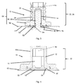
- the plastic cap 10 is suitable to cover a bolt 58. As already in Fig. 3 or in Fig. 5 illustrated, the plastic cap 10 is a part of an assembly 60, which has a bolt 58 and a plate 62 with a plate opening 64.
- the bolt 58 comprises a head portion 66 and a bolt portion 68.
- the bolt 58 is, for example, as described, a press-in bolt.
- the bolt portion 68 is provided with a thread.
- the bolt 58 is connected to the pre-punched plate 62.
- the bolt 58 is inserted in a pre-punched pre-hole (the opening) of the sheet.
- the sheet 62 has a first side 70 and a second side 72.
- the sheet 62 extends substantially in a plane.
- the plate opening 64 the plate 62 is bent (see Fig. 3 ), which forms a recess 74. This area forms a knockout area.
- the sheet 62 is preferably an aluminum sheet.
- the sheet 62 may also be a steel sheet.
- the aluminum sheet can be thin. The thickness of the sheet 62 may be, for example, between 1 and 3 millimeters, and more preferably between 1 and 1.5 millimeters.
- the bolt 58 is pressed into the plate 62 through the opening until the abutment of the head portion on the first side 70 of the sheet.
- the plastic cap 10 (and in particular the first area) are pressed as a die on the bolt portion 68 until at first the first sealing ring 42 on the second side 72 of Sheet 62 is present.
- the second sealing ring 50 will abut the second side 72 of the sheet 62.
- the receptacle 14 of the plastic cap 10 is pressed over the bolt portion 68.
- the cross section of the receptacle 14 is dimensioned so that the bolt portion 68 can be pressed into the receptacle 14 without damaging the thread, but to hold the plastic cap 10 firmly.
- the plastic cap 10 and bolt 58 cooperate to level the plate 62 (or recess 74).
- the second sealing ring 50 is applied to the sheet surface and dodge elastically to the side with further pressing. This deformation of the second sealing ring 50 will enhance the tightness so that no liquid medium can enter within the receptacle 14.
- the second sealing ring 50 can thus compensate for the springback movement of the sheet and the possibly not fully flat sheet 62 and at the same time ensure the tightness.
- the second sealing ring 50 is located opposite the recess 74.
- the first sealing ring 42 is opposite to the sheet, but outside the recess 74.
- the first sealing ring 42 is opposite to a portion of the sheet, which was already straight before being pressed.
- the assembly 60 thus produced (i.e., sheet 62, pin 58 and plastic cap 10 pressed over the pin 58 and applied to the second side of the sheet 62) may be supplied to a liquid medium.
- this liquid medium can be a corrosion inhibitor.
- the liquid medium is for example a cathodic dip.
- the two sealing rings 42, 50 allow a total sealing without additional measures on the connection or on pressing tools or complex rework.
- the pin 58 can tear off part of the plastic of the plastic cap 10 which forms the receptacle 14.
- the part of the plastic may, for example, stick to the thread of the bolt, which requires a cleaning of the bolt.
- the first region has an outer surface.
- the outer surface may have a hexagonal area.
- One of the walls may be a flexible wall 76, and move on the bolt 58 during pressing of the plastic cap 10 (and in particular the first area).
- two opposing walls can be flexible walls76.
- the two flexible walls 76 Compared to the other walls 78 (referred to as "non-flexible"), the two flexible walls 76 have a smaller wall thickness.
- the flexible walls 76 have a wall thickness between 0.5 millimeters and 1.5 millimeters.
- the other walls 78 may for example have a wall thickness between 1.5 millimeters and 2.5 millimeters.
- the flexible wall 76 has an inner surface facing toward the receptacle 14 and an opposite outer surface.
- a ramp 80 may be disposed on the outer surface.
- the inner surface has, for example, a rib 82.
- the ramp 80 and / or the rib 82 may be located in the middle of the wall.
- the rib 82 and the ramp 80 are disposed opposite to each other, for example.
- the rib or ribs 82
- the ribs 82 of the two opposing walls cooperate to apply pressure to the pin portion 68.
- the ribs 82 will press on pushing the plastic cap 10 to the bolt portion 68.
- the ribs 82 are arranged so that they overlap with the bolt 58.
- the ramp 80 may increase the pressure on the bolt portion 68 through the rib 82.
- the sliding sleeve when pushed over the first area under its pressure, may create a pressure on the ramp that is passed to the ribs.
- two flexible walls are provided. But in other embodiments, only one or even more than two flexible walls may be provided.
- the plastic cap 10 could be pressed with play on the bolt and only when pushing down the plastic cap 10, the pressure on the ramp could be exerted on the bolt and the Festin the plastic cap 10 can be ensured.
- the receptacle 14 formed by the ribs and the inner walls (and in particular the receptacle 14kontur) lies within the second sealing ring contour.
- the plastic cap 10 After being fed into the liquid medium of the thus formed arrangement, the plastic cap 10 is pulled off (or unscrewed) from the bolt section.
- the sliding sleeve on its outer peripheral surface on the engagement features.
Landscapes
- Engineering & Computer Science (AREA)
- General Engineering & Computer Science (AREA)
- Mechanical Engineering (AREA)
- Closures For Containers (AREA)
Priority Applications (1)
| Application Number | Priority Date | Filing Date | Title |
|---|---|---|---|
| EP16188266.7A EP3293404B1 (fr) | 2016-09-12 | 2016-09-12 | Systeme comprenant une pastille plastique |
Applications Claiming Priority (1)
| Application Number | Priority Date | Filing Date | Title |
|---|---|---|---|
| EP16188266.7A EP3293404B1 (fr) | 2016-09-12 | 2016-09-12 | Systeme comprenant une pastille plastique |
Publications (2)
| Publication Number | Publication Date |
|---|---|
| EP3293404A1 true EP3293404A1 (fr) | 2018-03-14 |
| EP3293404B1 EP3293404B1 (fr) | 2020-03-18 |
Family
ID=56920564
Family Applications (1)
| Application Number | Title | Priority Date | Filing Date |
|---|---|---|---|
| EP16188266.7A Active EP3293404B1 (fr) | 2016-09-12 | 2016-09-12 | Systeme comprenant une pastille plastique |
Country Status (1)
| Country | Link |
|---|---|
| EP (1) | EP3293404B1 (fr) |
Cited By (4)
| Publication number | Priority date | Publication date | Assignee | Title |
|---|---|---|---|---|
| WO2020025177A1 (fr) * | 2018-08-03 | 2020-02-06 | Fairchild Fasteners Europe - Camloc Gmbh | Insert pour relier une connexion électrique à un mur et capuchon de protection pour un insert |
| CN112728083A (zh) * | 2020-12-31 | 2021-04-30 | 科华恒盛股份有限公司 | 一种密封结构及相关的接线结构和电气设备 |
| DE102021210573A1 (de) | 2021-09-23 | 2023-03-23 | Robert Bosch Gesellschaft mit beschränkter Haftung | Erdungskontaktsystem, Gerätegehäuse, Geräteeinheit, Wärmepumpeneinheit und Verfahren zur Herstellung eines Erdungskontaktsystems |
| EP3651279B1 (fr) * | 2018-11-08 | 2025-02-12 | Contemporary Amperex Technology (Hong Kong) Limited | Connecteur multifonctionnel haute tension et produit de batterie |
Citations (7)
| Publication number | Priority date | Publication date | Assignee | Title |
|---|---|---|---|---|
| US3273441A (en) * | 1962-01-19 | 1966-09-20 | Illinois Tool Works | Nut construction |
| DE2022907A1 (de) * | 1969-05-16 | 1970-11-26 | Usm Corp | Schraube |
| FR2398913A1 (fr) * | 1977-07-29 | 1979-02-23 | Mustad & Figlio Spa | Vis a capuchon d'etancheite et autotaraudeuse, notamment pour couvertures de batiments |
| DE3033714A1 (de) * | 1979-09-10 | 1981-03-26 | Fuji Seimitsu Mfg. Co. Ltd., Toyonaka, Osaka | Abdeckkappe fuer eine mutter |
| DE29720454U1 (de) | 1997-11-18 | 1999-04-01 | Emhart Inc., Newark, Del. | Abdeckkappe |
| DE102012016244A1 (de) * | 2012-08-16 | 2014-02-20 | GM Global Technology Operations LLC (n. d. Gesetzen des Staates Delaware) | Masseanschluss-Anordnung |
| DE102014009410A1 (de) | 2014-06-25 | 2015-12-31 | Audi Ag | Verfahren zum Verbinden eines Einpressbolzens mit einem ein Vorloch aufweisenden Blechteil und Abdeckelement zur Durchführung des Verfahrens |
-
2016
- 2016-09-12 EP EP16188266.7A patent/EP3293404B1/fr active Active
Patent Citations (7)
| Publication number | Priority date | Publication date | Assignee | Title |
|---|---|---|---|---|
| US3273441A (en) * | 1962-01-19 | 1966-09-20 | Illinois Tool Works | Nut construction |
| DE2022907A1 (de) * | 1969-05-16 | 1970-11-26 | Usm Corp | Schraube |
| FR2398913A1 (fr) * | 1977-07-29 | 1979-02-23 | Mustad & Figlio Spa | Vis a capuchon d'etancheite et autotaraudeuse, notamment pour couvertures de batiments |
| DE3033714A1 (de) * | 1979-09-10 | 1981-03-26 | Fuji Seimitsu Mfg. Co. Ltd., Toyonaka, Osaka | Abdeckkappe fuer eine mutter |
| DE29720454U1 (de) | 1997-11-18 | 1999-04-01 | Emhart Inc., Newark, Del. | Abdeckkappe |
| DE102012016244A1 (de) * | 2012-08-16 | 2014-02-20 | GM Global Technology Operations LLC (n. d. Gesetzen des Staates Delaware) | Masseanschluss-Anordnung |
| DE102014009410A1 (de) | 2014-06-25 | 2015-12-31 | Audi Ag | Verfahren zum Verbinden eines Einpressbolzens mit einem ein Vorloch aufweisenden Blechteil und Abdeckelement zur Durchführung des Verfahrens |
Cited By (7)
| Publication number | Priority date | Publication date | Assignee | Title |
|---|---|---|---|---|
| WO2020025177A1 (fr) * | 2018-08-03 | 2020-02-06 | Fairchild Fasteners Europe - Camloc Gmbh | Insert pour relier une connexion électrique à un mur et capuchon de protection pour un insert |
| KR20210027379A (ko) * | 2018-08-03 | 2021-03-10 | 페어차일드 패스너스 유럽 - 캠록 게엠베하 | 전기 연결부를 벽에 연결하기 위한 인서트 및 인서트용 보호 캡 |
| AU2019314862B2 (en) * | 2018-08-03 | 2022-03-03 | Fairchild Fasteners Europe - Camloc Gmbh | Insert for connecting an electric connection to a wall, and protective cap for an insert |
| US11336063B2 (en) | 2018-08-03 | 2022-05-17 | Fairchild Fasteners Europe—Camloc GmbH | Insert for connecting an electric connection to a wall, and protective cap for an insert |
| EP3651279B1 (fr) * | 2018-11-08 | 2025-02-12 | Contemporary Amperex Technology (Hong Kong) Limited | Connecteur multifonctionnel haute tension et produit de batterie |
| CN112728083A (zh) * | 2020-12-31 | 2021-04-30 | 科华恒盛股份有限公司 | 一种密封结构及相关的接线结构和电气设备 |
| DE102021210573A1 (de) | 2021-09-23 | 2023-03-23 | Robert Bosch Gesellschaft mit beschränkter Haftung | Erdungskontaktsystem, Gerätegehäuse, Geräteeinheit, Wärmepumpeneinheit und Verfahren zur Herstellung eines Erdungskontaktsystems |
Also Published As
| Publication number | Publication date |
|---|---|
| EP3293404B1 (fr) | 2020-03-18 |
Similar Documents
| Publication | Publication Date | Title |
|---|---|---|
| DE69227084T2 (de) | Erdungsbolzen | |
| EP2136088B1 (fr) | Elément de liaison doté d'une vis et d'une douille agencée sur celle-ci de façon inamovible | |
| EP2809463B1 (fr) | Tête d'expansion pour outils d'élargissement, outil d'expansion comprenant ladite tête et utilisation de ladite tête d'expansion et dudit outil d'expansion | |
| DE69419890T2 (de) | Vorrichtung zur Herstellung selbststanzender Muttern | |
| WO1994001688A1 (fr) | Element d'insertion utilise comme element d'assemblage pour assemblage resistant a l'ejection et ne devant pas tourner | |
| EP3309414B1 (fr) | Élément de fonction pour fixation étanche aux fluides sur une pièce de tôlerie, ensemble de montage et procédé | |
| DE102015115890A1 (de) | Anordnung zur Herstellung einer Rohrverbindung und Halteelement für eine solche Anordnung | |
| EP2047125A1 (fr) | Manchon | |
| EP3293404B1 (fr) | Systeme comprenant une pastille plastique | |
| DE102014009410B4 (de) | Verfahren zum Verbinden eines Einpressbolzens mit einem ein Vorloch aufweisenden Blechteil und Abdeckelement zur Durchführung des Verfahrens | |
| EP3707396A1 (fr) | Dispositif anti-détachement pour vis et unité de montage | |
| EP3778356A1 (fr) | Bouchon d'obturation | |
| DE102015211857A1 (de) | Lagerring, Verfahren zur Herstellung eines solchen Rings und Lager, das einen solchen Ring enthält | |
| DE102013007036A1 (de) | Kontaktiereinrichtung für eine elektrische Kontaktanordnung sowie Verfahren zu deren Herstellung | |
| EP2141370A1 (fr) | Elément de fixation | |
| WO2022152903A1 (fr) | Rondelle de blocage et son procédé de production, et raccord à vis utilisant une telle rondelle de blocage | |
| DE102021119824A1 (de) | Stanzniet und Verfahren zum Stanznieten mindestens zweier Bauteile | |
| EP4023894B1 (fr) | Élément fonctionnel, composant d'assemblage et procédé de fabrication d'un composant d'assemblage | |
| EP3956572B1 (fr) | Unité de raccordement et procédé de fabrication d'une unité de raccordement | |
| DE19639007A1 (de) | Befestigungselement zum Einnieten in eine Lochkontur eines flächigen Bauteiles | |
| EP4083451A1 (fr) | Élément fonctionnel auto-poinçonnant, composant d'assemblage et procédé de fabrication d'un composant d'assemblage | |
| DE102016104396A1 (de) | Elektrisches Massesystem und Masseverbindungs-Herstellungsverfahren | |
| DE102008059343B4 (de) | Nietteil in einer Bauteilausnehmung | |
| WO2009112469A1 (fr) | Pièce de vissage pour une fixation d'une jante d'une automobile | |
| EP3988803B1 (fr) | Unité fonctionnelle pourvue d'élément de connexion et d'élément de fixation |
Legal Events
| Date | Code | Title | Description |
|---|---|---|---|
| PUAI | Public reference made under article 153(3) epc to a published international application that has entered the european phase |
Free format text: ORIGINAL CODE: 0009012 |
|
| STAA | Information on the status of an ep patent application or granted ep patent |
Free format text: STATUS: THE APPLICATION HAS BEEN PUBLISHED |
|
| AK | Designated contracting states |
Kind code of ref document: A1 Designated state(s): AL AT BE BG CH CY CZ DE DK EE ES FI FR GB GR HR HU IE IS IT LI LT LU LV MC MK MT NL NO PL PT RO RS SE SI SK SM TR |
|
| AX | Request for extension of the european patent |
Extension state: BA ME |
|
| STAA | Information on the status of an ep patent application or granted ep patent |
Free format text: STATUS: REQUEST FOR EXAMINATION WAS MADE |
|
| 17P | Request for examination filed |
Effective date: 20180822 |
|
| RBV | Designated contracting states (corrected) |
Designated state(s): AL AT BE BG CH CY CZ DE DK EE ES FI FR GB GR HR HU IE IS IT LI LT LU LV MC MK MT NL NO PL PT RO RS SE SI SK SM TR |
|
| RIC1 | Information provided on ipc code assigned before grant |
Ipc: F16B 37/08 20060101ALN20190821BHEP Ipc: H01R 4/64 20060101ALI20190821BHEP Ipc: F16B 37/14 20060101ALI20190821BHEP Ipc: F16B 33/00 20060101AFI20190821BHEP |
|
| GRAP | Despatch of communication of intention to grant a patent |
Free format text: ORIGINAL CODE: EPIDOSNIGR1 |
|
| STAA | Information on the status of an ep patent application or granted ep patent |
Free format text: STATUS: GRANT OF PATENT IS INTENDED |
|
| RIC1 | Information provided on ipc code assigned before grant |
Ipc: F16B 37/08 20060101ALN20190924BHEP Ipc: H01R 4/64 20060101ALI20190924BHEP Ipc: F16B 37/14 20060101ALI20190924BHEP Ipc: F16B 33/00 20060101AFI20190924BHEP |
|
| INTG | Intention to grant announced |
Effective date: 20191009 |
|
| GRAS | Grant fee paid |
Free format text: ORIGINAL CODE: EPIDOSNIGR3 |
|
| GRAA | (expected) grant |
Free format text: ORIGINAL CODE: 0009210 |
|
| STAA | Information on the status of an ep patent application or granted ep patent |
Free format text: STATUS: THE PATENT HAS BEEN GRANTED |
|
| RIN1 | Information on inventor provided before grant (corrected) |
Inventor name: ROSEMANN, FRANK Inventor name: KEMPF, CHRISTIAN Inventor name: BRUMM, MATHIAS |
|
| AK | Designated contracting states |
Kind code of ref document: B1 Designated state(s): AL AT BE BG CH CY CZ DE DK EE ES FI FR GB GR HR HU IE IS IT LI LT LU LV MC MK MT NL NO PL PT RO RS SE SI SK SM TR |
|
| REG | Reference to a national code |
Ref country code: GB Ref legal event code: FG4D Free format text: NOT ENGLISH |
|
| REG | Reference to a national code |
Ref country code: DE Ref legal event code: R096 Ref document number: 502016009181 Country of ref document: DE |
|
| REG | Reference to a national code |
Ref country code: AT Ref legal event code: REF Ref document number: 1246212 Country of ref document: AT Kind code of ref document: T Effective date: 20200415 Ref country code: IE Ref legal event code: FG4D Free format text: LANGUAGE OF EP DOCUMENT: GERMAN |
|
| PG25 | Lapsed in a contracting state [announced via postgrant information from national office to epo] |
Ref country code: RS Free format text: LAPSE BECAUSE OF FAILURE TO SUBMIT A TRANSLATION OF THE DESCRIPTION OR TO PAY THE FEE WITHIN THE PRESCRIBED TIME-LIMIT Effective date: 20200318 Ref country code: FI Free format text: LAPSE BECAUSE OF FAILURE TO SUBMIT A TRANSLATION OF THE DESCRIPTION OR TO PAY THE FEE WITHIN THE PRESCRIBED TIME-LIMIT Effective date: 20200318 Ref country code: NO Free format text: LAPSE BECAUSE OF FAILURE TO SUBMIT A TRANSLATION OF THE DESCRIPTION OR TO PAY THE FEE WITHIN THE PRESCRIBED TIME-LIMIT Effective date: 20200618 |
|
| REG | Reference to a national code |
Ref country code: NL Ref legal event code: MP Effective date: 20200318 |
|
| PG25 | Lapsed in a contracting state [announced via postgrant information from national office to epo] |
Ref country code: SE Free format text: LAPSE BECAUSE OF FAILURE TO SUBMIT A TRANSLATION OF THE DESCRIPTION OR TO PAY THE FEE WITHIN THE PRESCRIBED TIME-LIMIT Effective date: 20200318 Ref country code: HR Free format text: LAPSE BECAUSE OF FAILURE TO SUBMIT A TRANSLATION OF THE DESCRIPTION OR TO PAY THE FEE WITHIN THE PRESCRIBED TIME-LIMIT Effective date: 20200318 Ref country code: BG Free format text: LAPSE BECAUSE OF FAILURE TO SUBMIT A TRANSLATION OF THE DESCRIPTION OR TO PAY THE FEE WITHIN THE PRESCRIBED TIME-LIMIT Effective date: 20200618 Ref country code: GR Free format text: LAPSE BECAUSE OF FAILURE TO SUBMIT A TRANSLATION OF THE DESCRIPTION OR TO PAY THE FEE WITHIN THE PRESCRIBED TIME-LIMIT Effective date: 20200619 Ref country code: LV Free format text: LAPSE BECAUSE OF FAILURE TO SUBMIT A TRANSLATION OF THE DESCRIPTION OR TO PAY THE FEE WITHIN THE PRESCRIBED TIME-LIMIT Effective date: 20200318 |
|
| REG | Reference to a national code |
Ref country code: LT Ref legal event code: MG4D |
|
| PG25 | Lapsed in a contracting state [announced via postgrant information from national office to epo] |
Ref country code: NL Free format text: LAPSE BECAUSE OF FAILURE TO SUBMIT A TRANSLATION OF THE DESCRIPTION OR TO PAY THE FEE WITHIN THE PRESCRIBED TIME-LIMIT Effective date: 20200318 |
|
| PG25 | Lapsed in a contracting state [announced via postgrant information from national office to epo] |
Ref country code: CZ Free format text: LAPSE BECAUSE OF FAILURE TO SUBMIT A TRANSLATION OF THE DESCRIPTION OR TO PAY THE FEE WITHIN THE PRESCRIBED TIME-LIMIT Effective date: 20200318 Ref country code: IS Free format text: LAPSE BECAUSE OF FAILURE TO SUBMIT A TRANSLATION OF THE DESCRIPTION OR TO PAY THE FEE WITHIN THE PRESCRIBED TIME-LIMIT Effective date: 20200718 Ref country code: RO Free format text: LAPSE BECAUSE OF FAILURE TO SUBMIT A TRANSLATION OF THE DESCRIPTION OR TO PAY THE FEE WITHIN THE PRESCRIBED TIME-LIMIT Effective date: 20200318 Ref country code: SK Free format text: LAPSE BECAUSE OF FAILURE TO SUBMIT A TRANSLATION OF THE DESCRIPTION OR TO PAY THE FEE WITHIN THE PRESCRIBED TIME-LIMIT Effective date: 20200318 Ref country code: EE Free format text: LAPSE BECAUSE OF FAILURE TO SUBMIT A TRANSLATION OF THE DESCRIPTION OR TO PAY THE FEE WITHIN THE PRESCRIBED TIME-LIMIT Effective date: 20200318 Ref country code: SM Free format text: LAPSE BECAUSE OF FAILURE TO SUBMIT A TRANSLATION OF THE DESCRIPTION OR TO PAY THE FEE WITHIN THE PRESCRIBED TIME-LIMIT Effective date: 20200318 Ref country code: PT Free format text: LAPSE BECAUSE OF FAILURE TO SUBMIT A TRANSLATION OF THE DESCRIPTION OR TO PAY THE FEE WITHIN THE PRESCRIBED TIME-LIMIT Effective date: 20200812 Ref country code: LT Free format text: LAPSE BECAUSE OF FAILURE TO SUBMIT A TRANSLATION OF THE DESCRIPTION OR TO PAY THE FEE WITHIN THE PRESCRIBED TIME-LIMIT Effective date: 20200318 |
|
| REG | Reference to a national code |
Ref country code: DE Ref legal event code: R097 Ref document number: 502016009181 Country of ref document: DE |
|
| PLBE | No opposition filed within time limit |
Free format text: ORIGINAL CODE: 0009261 |
|
| STAA | Information on the status of an ep patent application or granted ep patent |
Free format text: STATUS: NO OPPOSITION FILED WITHIN TIME LIMIT |
|
| PG25 | Lapsed in a contracting state [announced via postgrant information from national office to epo] |
Ref country code: DK Free format text: LAPSE BECAUSE OF FAILURE TO SUBMIT A TRANSLATION OF THE DESCRIPTION OR TO PAY THE FEE WITHIN THE PRESCRIBED TIME-LIMIT Effective date: 20200318 Ref country code: ES Free format text: LAPSE BECAUSE OF FAILURE TO SUBMIT A TRANSLATION OF THE DESCRIPTION OR TO PAY THE FEE WITHIN THE PRESCRIBED TIME-LIMIT Effective date: 20200318 Ref country code: IT Free format text: LAPSE BECAUSE OF FAILURE TO SUBMIT A TRANSLATION OF THE DESCRIPTION OR TO PAY THE FEE WITHIN THE PRESCRIBED TIME-LIMIT Effective date: 20200318 |
|
| 26N | No opposition filed |
Effective date: 20201221 |
|
| PG25 | Lapsed in a contracting state [announced via postgrant information from national office to epo] |
Ref country code: PL Free format text: LAPSE BECAUSE OF FAILURE TO SUBMIT A TRANSLATION OF THE DESCRIPTION OR TO PAY THE FEE WITHIN THE PRESCRIBED TIME-LIMIT Effective date: 20200318 |
|
| REG | Reference to a national code |
Ref country code: CH Ref legal event code: PL |
|
| GBPC | Gb: european patent ceased through non-payment of renewal fee |
Effective date: 20200912 |
|
| PG25 | Lapsed in a contracting state [announced via postgrant information from national office to epo] |
Ref country code: SI Free format text: LAPSE BECAUSE OF FAILURE TO SUBMIT A TRANSLATION OF THE DESCRIPTION OR TO PAY THE FEE WITHIN THE PRESCRIBED TIME-LIMIT Effective date: 20200318 |
|
| REG | Reference to a national code |
Ref country code: BE Ref legal event code: MM Effective date: 20200930 |
|
| PG25 | Lapsed in a contracting state [announced via postgrant information from national office to epo] |
Ref country code: LU Free format text: LAPSE BECAUSE OF NON-PAYMENT OF DUE FEES Effective date: 20200912 |
|
| PG25 | Lapsed in a contracting state [announced via postgrant information from national office to epo] |
Ref country code: FR Free format text: LAPSE BECAUSE OF NON-PAYMENT OF DUE FEES Effective date: 20200930 |
|
| PG25 | Lapsed in a contracting state [announced via postgrant information from national office to epo] |
Ref country code: CH Free format text: LAPSE BECAUSE OF NON-PAYMENT OF DUE FEES Effective date: 20200930 Ref country code: BE Free format text: LAPSE BECAUSE OF NON-PAYMENT OF DUE FEES Effective date: 20200930 Ref country code: LI Free format text: LAPSE BECAUSE OF NON-PAYMENT OF DUE FEES Effective date: 20200930 Ref country code: GB Free format text: LAPSE BECAUSE OF NON-PAYMENT OF DUE FEES Effective date: 20200912 Ref country code: IE Free format text: LAPSE BECAUSE OF NON-PAYMENT OF DUE FEES Effective date: 20200912 |
|
| PG25 | Lapsed in a contracting state [announced via postgrant information from national office to epo] |
Ref country code: TR Free format text: LAPSE BECAUSE OF FAILURE TO SUBMIT A TRANSLATION OF THE DESCRIPTION OR TO PAY THE FEE WITHIN THE PRESCRIBED TIME-LIMIT Effective date: 20200318 Ref country code: MT Free format text: LAPSE BECAUSE OF FAILURE TO SUBMIT A TRANSLATION OF THE DESCRIPTION OR TO PAY THE FEE WITHIN THE PRESCRIBED TIME-LIMIT Effective date: 20200318 Ref country code: CY Free format text: LAPSE BECAUSE OF FAILURE TO SUBMIT A TRANSLATION OF THE DESCRIPTION OR TO PAY THE FEE WITHIN THE PRESCRIBED TIME-LIMIT Effective date: 20200318 |
|
| PG25 | Lapsed in a contracting state [announced via postgrant information from national office to epo] |
Ref country code: MK Free format text: LAPSE BECAUSE OF FAILURE TO SUBMIT A TRANSLATION OF THE DESCRIPTION OR TO PAY THE FEE WITHIN THE PRESCRIBED TIME-LIMIT Effective date: 20200318 Ref country code: MC Free format text: LAPSE BECAUSE OF FAILURE TO SUBMIT A TRANSLATION OF THE DESCRIPTION OR TO PAY THE FEE WITHIN THE PRESCRIBED TIME-LIMIT Effective date: 20200318 Ref country code: AL Free format text: LAPSE BECAUSE OF FAILURE TO SUBMIT A TRANSLATION OF THE DESCRIPTION OR TO PAY THE FEE WITHIN THE PRESCRIBED TIME-LIMIT Effective date: 20200318 |
|
| REG | Reference to a national code |
Ref country code: AT Ref legal event code: MM01 Ref document number: 1246212 Country of ref document: AT Kind code of ref document: T Effective date: 20210912 |
|
| PG25 | Lapsed in a contracting state [announced via postgrant information from national office to epo] |
Ref country code: AT Free format text: LAPSE BECAUSE OF NON-PAYMENT OF DUE FEES Effective date: 20210912 |
|
| PGFP | Annual fee paid to national office [announced via postgrant information from national office to epo] |
Ref country code: DE Payment date: 20250919 Year of fee payment: 10 |