EP3293422B1 - Montageanordnung für planetengetriebe - Google Patents
Montageanordnung für planetengetriebe Download PDFInfo
- Publication number
- EP3293422B1 EP3293422B1 EP17186802.9A EP17186802A EP3293422B1 EP 3293422 B1 EP3293422 B1 EP 3293422B1 EP 17186802 A EP17186802 A EP 17186802A EP 3293422 B1 EP3293422 B1 EP 3293422B1
- Authority
- EP
- European Patent Office
- Prior art keywords
- planet
- pin
- carrier
- planet pin
- axis
- Prior art date
- Legal status (The legal status is an assumption and is not a legal conclusion. Google has not performed a legal analysis and makes no representation as to the accuracy of the status listed.)
- Active
Links
Images


Classifications
-
- F—MECHANICAL ENGINEERING; LIGHTING; HEATING; WEAPONS; BLASTING
- F16—ENGINEERING ELEMENTS AND UNITS; GENERAL MEASURES FOR PRODUCING AND MAINTAINING EFFECTIVE FUNCTIONING OF MACHINES OR INSTALLATIONS; THERMAL INSULATION IN GENERAL
- F16H—GEARING
- F16H57/00—General details of gearing
- F16H57/08—General details of gearing of gearings with members having orbital motion
- F16H57/082—Planet carriers
-
- F—MECHANICAL ENGINEERING; LIGHTING; HEATING; WEAPONS; BLASTING
- F02—COMBUSTION ENGINES; HOT-GAS OR COMBUSTION-PRODUCT ENGINE PLANTS
- F02C—GAS-TURBINE PLANTS; AIR INTAKES FOR JET-PROPULSION PLANTS; CONTROLLING FUEL SUPPLY IN AIR-BREATHING JET-PROPULSION PLANTS
- F02C7/00—Features, components parts, details or accessories, not provided for in, or of interest apart form groups F02C1/00 - F02C6/00; Air intakes for jet-propulsion plants
- F02C7/36—Power transmission arrangements between the different shafts of the gas turbine plant, or between the gas-turbine plant and the power user
-
- F—MECHANICAL ENGINEERING; LIGHTING; HEATING; WEAPONS; BLASTING
- F05—INDEXING SCHEMES RELATING TO ENGINES OR PUMPS IN VARIOUS SUBCLASSES OF CLASSES F01-F04
- F05D—INDEXING SCHEME FOR ASPECTS RELATING TO NON-POSITIVE-DISPLACEMENT MACHINES OR ENGINES, GAS-TURBINES OR JET-PROPULSION PLANTS
- F05D2240/00—Components
- F05D2240/90—Mounting on supporting structures or systems
- F05D2240/91—Mounting on supporting structures or systems on a stationary structure
-
- F—MECHANICAL ENGINEERING; LIGHTING; HEATING; WEAPONS; BLASTING
- F05—INDEXING SCHEMES RELATING TO ENGINES OR PUMPS IN VARIOUS SUBCLASSES OF CLASSES F01-F04
- F05D—INDEXING SCHEME FOR ASPECTS RELATING TO NON-POSITIVE-DISPLACEMENT MACHINES OR ENGINES, GAS-TURBINES OR JET-PROPULSION PLANTS
- F05D2260/00—Function
- F05D2260/30—Retaining components in desired mutual position
- F05D2260/36—Retaining components in desired mutual position by a form fit connection, e.g. by interlocking
-
- F—MECHANICAL ENGINEERING; LIGHTING; HEATING; WEAPONS; BLASTING
- F05—INDEXING SCHEMES RELATING TO ENGINES OR PUMPS IN VARIOUS SUBCLASSES OF CLASSES F01-F04
- F05D—INDEXING SCHEME FOR ASPECTS RELATING TO NON-POSITIVE-DISPLACEMENT MACHINES OR ENGINES, GAS-TURBINES OR JET-PROPULSION PLANTS
- F05D2260/00—Function
- F05D2260/40—Transmission of power
- F05D2260/403—Transmission of power through the shape of the drive components
- F05D2260/4031—Transmission of power through the shape of the drive components as in toothed gearing
- F05D2260/40311—Transmission of power through the shape of the drive components as in toothed gearing of the epicyclical, planetary or differential type
-
- F—MECHANICAL ENGINEERING; LIGHTING; HEATING; WEAPONS; BLASTING
- F16—ENGINEERING ELEMENTS AND UNITS; GENERAL MEASURES FOR PRODUCING AND MAINTAINING EFFECTIVE FUNCTIONING OF MACHINES OR INSTALLATIONS; THERMAL INSULATION IN GENERAL
- F16H—GEARING
- F16H1/00—Toothed gearings for conveying rotary motion
- F16H1/28—Toothed gearings for conveying rotary motion with gears having orbital motion
Definitions
- the present invention relates to a planet carrier for a planetary gear train.
- the invention may also relate to a planet pin for use with the carrier.
- the invention is particularly suited to gas turbine engine power gear box applications and wind turbines.
- the gear train allows the low pressure spool to be driven at higher rotational speeds which provides for a more efficient lighter engine core, whilst reducing the speed of the fan allows it to be a larger diameter thereby providing a higher bypass ratio.
- the reduction gear trains may be epicyclically configured where the fan is driven via the carrier of a planetary configuration, or a star configuration where the planet gears are fixed and the fan shaft is driven by the ring or star gear.
- Figure 1 shows a geared gas turbine engine 10 having a fan 12, low and high pressure spools, each having respective compressors and turbines driveably interconnected by respective shafts which are rotatable about a principal axis 11.
- a low pressure compressor 15 connected to the low pressure turbine 19 via a low pressure shaft
- a high pressure compressor 16 connected to a high pressure turbine 18 via a high pressure shaft.
- the low 15 and high 16 pressure compressors progressively compress air from an inlet downstream of a fan 12 to an outlet in flow proximity to the combustor 17.
- Compressed air flows from the high pressure compressor 16 to the combustor 17 in which fuel is added and the mixture burnt.
- the combusted gas then expands through and drives the high 18 and low 19 pressure turbines in flow series.
- the low and high pressure shafts interconnect the respective turbines and compressors provide the drive for the compressors.
- the fan 12 is located at the front of the engine 10 to provide air for the inlet of the compressors and the main propulsive flow which is channelled down the bypass duct 22.
- the fan 12 is driveably connected to the low pressure shaft via a gear train 14 in the form of an epicyclic reduction gear box.
- the gear train 14 is located between the low pressure shaft and the fan 12 and is arranged to reduce the speed of the fan 12 relative to the speed of the low pressure turbine 19.
- Such an arrangement allows for a higher speed and more efficient low pressure turbine 19 together with and slow spinning larger fan which can provide a higher bypass ratio. This combination allows the speed of the fan and low pressure turbine to be independently optimised.
- the fan 12 has a plurality fan blades 13 extending radially from a hub which is mounted so as to rotate about the principal axis of the engine 10.
- the fan 12 resides within a fan casing 21 which partially defines the bypass duct 22.
- An engine casing surrounds the engine core which comprises the low and high pressure spools and combustor 17.
- the engine casing generally provides containment and structural support for the engine core.
- the engine casing is ultimately attached to and supported by the wing of the aircraft via an appropriate arrangement of struts which extend across the bypass duct and the nacelle which attaches to a pylon as is well known in the art.
- the gear train 14 is in the form of an epicyclic reduction gearbox which is driven in a planetary configuration.
- the gear train 14 includes a ring or annular gear which is held substantially stationary in relation to the engine casing, a planet gear set with individual planets gears interconnected via a carrier, and a sun gear.
- the sun gear is rotatably connected to the low pressure shaft.
- the fan 12 is connected to the output shaft of the gearbox which is in the form of the carrier of the planet gear via a fan shafting arrangement.
- planetary gearboxes are used in power transmission systems across many industries including, for example: automotive, wind turbines, aerospace and marine.
- it comprises a central gear or sun gear surrounded by multiple planet gears mounted on a single carrier, which in turn sits within a single ring gear which has internal gear teeth for engagement with the planet.
- the sun gear, carrier and ring gear are concentrically with the engine principal axis 11.
- one of the sun gear, planet carrier and ring gear are held stationary with the other two providing an input and an output to the gearbox.
- This flexibility in selection of the various components as a stator or as an input or output rotors determines the gear ratio of the gearbox and allows for several drive variations, as are known in the art.
- the carrier forms a stiff structure around the gears to ensure efficient transfer of torque and reduce unnecessary gear wear.
- the axially opposed end walls of the carrier include apertures into which a so-called planet pin is inserted.
- the planet pin defines the central rotational axis of the respective planet gear and carries or includes the planet gear wheel bearing.
- the pins are fed into the apertures to locate the planet gears in the correct position in relation to the carrier.
- the pins are retained in the apertures, typically by a combination of interference fit and mechanical fasteners, such as bolts.
- the planet gear Under centrifugal loading the planet gear is forced radially outwards as the carrier spins. It is restrained by the planet pin via the planet bearing which becomes loaded on the radially inner surface, the radial inner surface being closest to the central axis of the carrier.
- the planet pin is restrained from moving by its fit within the carrier pin aperture in the axial wall which results in the radially outer portion of the carrier aperture carrying the load.
- the thin radial profile can result in a deflection under the centrifugally loaded planet pin which can result in significant deflection of the carrier plate and its rim.
- the planet pin can be deformed by the centrifugal loading induced by the planet gear.
- the combined effect of these load induced deformations can be to move the planet gear radially outwards by an appreciable amount. Such a movement can affect gear meshing and deleterious levels of wear.
- European Patent Application EP 0274874 A2 discloses a planetary carrier assembly having first and second walls having bores to support the planetary pins which in turn are used to support the gear.
- the carrier has two separately sized bores that form a stepped profile, which extends around the planet retention pin. This stepped profile is only present on one side of the pin.
- German Patent Application DE 10 2013 216795 A1 discloses a planetary carrier assembly having first and second walls.
- the planet pin is provided with a stepped section, such that it has a narrower diameter section for engagement with the first and second walls. It is the presence of this narrower section acts as the retention means.
- Chinese Utility Patent CN 203 258 045 U discloses a planetary carrier assembly having a single wall.
- the planetary pin is mounted to the carrier wall via a pressing plate.
- the carrier wall is shaped to allow for a cone ring to be positioned between the carrier plate and the gear about the carrier pin.
- the present invention seeks to provide an improved planet pin and carrier for a planet gear.
- the present invention provides a planet carrier according to the appended claims.
- the planet carrier may comprise:a planet pin for receiving a planet gear, the planet pin having a body with an external surface for receiving a planet gear bearing or planet gear.
- a carrier may have a first axial wall and a second axial wall with the planet pin extending therebetween along a planet pin axis.
- Each carrier wall may include a planet pin retention feature located on the radially inner surfaces of the carrier wall and within a radially outer or external surface of the planet pin and wherein the planet pin retention feature engages with the planet pin to provide radial retention of the planet pin with engagement being provided on at least one radially inner portion of the planet pin with respect to the carrier axis or principal axis of the gear box.
- Providing a planet pin retention feature radially inwards of the planet pin axis and engaged with a portion of the planet pin allows the centrifugal load exerted on the planet pin in use to be distributed to the carrier in an area less prone to distortion.
- the pin retention feature provides radial retention of the planet pin.
- the pin retention feature provides a location feature against which the centrifugal forces exerted on the planet pin in use can react.
- the planet pin retention feature may be a projection which extends from an inner surface of either or both of the first or second axial carrier wall and towards the body of the planet pin and includes an engagement surface which faces radially outwards from the planet pin axis.
- the engagement surface may be radially inwards of the planet pin axis with respect to the carrier axis.
- the projection may be an arcuate or annular rib.
- the projection may extend through at least 180 degrees and may have centre of curvature which is concentric with the planet pin axis.
- the planet pin may include an end surface with one or more walls or flanges which define a projection receiving hollow extending into the planet pin.
- the planet pin may be an elongate body.
- the body may be cylindrical.
- the body may include an inner and an outer wall extending longitudinally between a first and a second end face.
- the wall or flange may extend from either of the first or second end face of the pin.
- Each end face may include a wall or flange.
- the wall or flange may extend partially or fully around the periphery of the pin.
- the wall or flange may define an inner surface which abuts the engagement surface of corresponding outer surface of the carrier projection.
- the projection receiving hollow may define a circumferential pin rim on the end face of the pin.
- the pin rim may be on a periphery of the planet pin.
- the pin rim may extend only partially around the periphery of the pin, the terminal ends of the rim providing an opening for receiving the projection.
- the pin rim may be provided in the form of a U-shaped rim when viewed end on.
- the pin rim may extend around the rim for less than 180 degrees.
- the planet pin may be rotatably engaged with the projection.
- Either or both of the carrier and pin may include a locking mechanism which prevents rotation of the planet pin about the pin axis, once the pin is engaged.
- the carrier may comprise an assembly of a first part including the first axial wall, and a second part including the second axial wall.
- the carrier may also comprise a planet pin axial clamp which extends through the planet in and is arranged to prevent the separation of the first and second axial walls.
- a planetary gear train including the planet carrier, and a gas turbine engine including the planetary gear train.
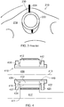
- FIG. 2a and 2b shows a typical carrier 210 from a planetary gearbox 14.
- the planet carrier 210 comprises a plurality of planet gears 212 which are equidistantly distributed at a constant radius around the circumference of the carrier 210. In the example shown, there are five planets gears.
- the planet gears 212 are exposed through the radially outer wall of the planet carrier 210 so that they can be driveably received within a ring gear 216.
- the planet carrier 210 has a central bore in which a sun gear 217 received.
- the planet gears 212 are exposed on the radially inner wall of the central core so as to be driveably engageable with the sun gear 217.
- the carrier 212 may be made up from two parts. Each of the two parts includes an axial end wall 218, 220. The two parts of the carrier 210 are placed in an abutting relation and attached together around a circumferential split line to provide a single rigid structural housing for the planet gears 212. It will be appreciated that the construction of the carrier may vary from this basic structure which is provided as an example only.
- the planet gears 212 are rotatably mounted within the carrier 210 by so-called planet pins 222 which extend between the two axial end walls 218, 220.
- the planet pins 222 in the example shown in Figure 2b pass through apertures in the axial end walls 218, 220 and are retained therein by the combination of interference fit and some other locking mechanism (not shown).
- Such a locking mechanism may include bolts, for example.
- FIG 3 shows a prior art arrangement of the carrier 210 from an axial end view.
- the carrier 210 is shown in a rotating state in which the planet pin 222 is centrifugally loaded as indicated by the thick arrow 224.
- the centrifugal loading placed on the pin 222 is a resultant combination of centrifugal forces acting on the pin 222, the bearing, and the planet gear 212. This can cause a significant deformation in the radially outer rim 230 of the carrier and can also cause transverse elongation of the planet pin 222 which is effectively squashed between the planet gear and carrier rim 230 under the centrifugal loading.
- the centrifugal loading also causes increased strain in the portions which surround the planet pin aperture in the carrier axial wall 218, 220.
- This problem is particularly relevant to large gearboxes such as those found in the aero industry applications and wind turbines, for example.
- Such features may include a preloaded interference fits, high clamping loads on the planet pins 222 with the use of threaded fasteners, or an increase in size of the carrier.
- Another option may be to permanently join the planet pin 222 to the carrier end wall 218, 220, for example by welding, however this is an inferior solution from a maintenance perspective as the gearbox cannot be easily disassembled.
- Figure 4 shows a partial section of a gear box having sun gear 417, received within a circular array of planet gears 412 individually rotatable about a planet gear axis 413 and held in a fixed relation to one another in a planet carrier 410 which in turn is inside a ring gear.
- the sun gear 417 and planet carrier 410 are rotatable about a carrier axis 411 and includes a planet pin 422 for receiving the planet gear 412.
- the carrier 410 has axially opposing end walls 418, 420.
- the pin 422 has a body 432 with an external surface 434 for receiving the planet gear bearing or planet gear, as the case may be.
- the planet pin 422 may be considered to include all or part of the planet bearing for the purpose of the description but they may be separate in a working embodiment.
- the planet pin 422 will typically be a cylindrical body which is elongate, having a longitudinal axis which defines the axis of rotation of the planet gear 412.
- the carrier 410 has a first axial wall 418 and a second axial wall 420 with the planet pin 422 extending therebetween a long a planet pin axis 413.
- Each carrier wall 418, 420 includes a planet pin retention feature 436 located on the radially inner surface of the carrier wall 418, 420 and within a radially outer or external surface 434 of the planet pin 422.
- the planet gear retention feature 436 is a projection which extends from an inner surface (in relation to the carrier) of the respective axial carrier wall 418, 420 and into the body or a wall of the planet pin 414.
- the planet pin retention feature 436 engages with the pin 422 to provide radial retention of the planet pin 422.
- the engagement is provided on at least one radially inner portion of the planet pin 422 with respect to the carrier axis 411 or principal axis of the gear box.
- the centrifugal loading on the planet pin 422 is carried by the portion of carrier wall 218, 220 which is radially inwards of or local to the radially inner portion of the planet pin aperture.
- the projection 436 may take any suitable form such as a single or plurality of pins or stumps, or, as per the example of Figure 4 , may include a rib 436.
- the rib 436 may be elongate so as to extend around the periphery of the pin aperture and have axial and radial depth in the longitudinal section of the planet carrier 410 and with respect to the longitudinal central axis.
- the rib 436 may be curved or arcuate. In the case of an arcuate rib 436, the rib 436 may be centred on the central axis 413 of the pin.
- the rib 436 can fully extend around the periphery of an axial wall aperture so as to be a continuous or fully annular feature.
- the carrier projection 436 provides an engagement surface for engagement with the corresponding feature of the pin 422 and providing radial restraint thereof.
- an engagement surface 437 facing radially inwards towards the carrier axis 411 which abuts a radially opposing surface of the gear pin 422.
- the engagement surface 437 faces radially outwards from the planet pin axis 413, and includes at least one part which is radially inwards of the planet pin axis with respect to the carrier axis 411.
- the rib 436 may extend orthogonally from the inner surface of the carrier axial wall 418, 420 and is thus parallel to the pin axis 413 in section.
- the axial and radial extent of the projection 436 will be determined in accordance with the mechanical requirements which, in part, will be determined by the centrifugal loading it will experience in service.
- the projections may be provided at a common radius from the planet pin axis 413.
- the pin 422 may include a corresponding feature to mateably receive the carrier projection 436.
- the pin may include a flange 442 or a hollow 438, 439 on or in the end face thereof.
- the hollow may take any suitable form such as a central bore 439 of the pin 422, a rebate or recess 438 provided in an external surface of the pin 422.
- the pin projection 442 may be provided in the form of one or more flanges which extend axially (with respect to the longitudinal axis of the pin) from the end of the pin 422.
- the carrier projection 436 may extend around the radially outer portion of the planet pin aperture, it will be appreciated that the centrifugal load is predominantly carried by the radially inner portion of the projection. Hence, it may be possible to have a projection which extends only partially around the planet pin.
- the rib may extend through an arc of less than 180 degrees. Further, the rib may be made from discrete sections of short or stumps ribs where the mechanical constraints allow.
- the carrier 413 shown in Figure 4 is a two part carrier similar to that shown in Figure 2a .
- the first and second axial end walls of the carrier are provided by first and second components which are clamped together at an abutting split line.
- an axial restraint or tether 440 may be included local to the planet pin 422.
- the tether 440 is a two part mechanical clamp which extends between and axially clamps the outer surfaces of the axial end walls 418, 420 to prevent their separation in use.
- there is a mechanical clamp 440 which passes through the central bore 439 of the planet pin 422 and is threadingly engaged to a corresponding nut which is located on the outer surface of the second axial end wall 420.
- the mechanical clamp 440 is in the form of a threaded tube which generally comprises a tubular body having a central bore therethrough.
- the first end of the threaded tube includes a flanged head which abuts the outer surface of the axial wall of the carrier when in situ.
- the second end 444 of the tubular body includes a thread which is received in the corresponding nut 446.
- the nut may be a separate element or may be fixedly attached to the outer surface of the second axial wall 420 of the carrier 413.
- the tube is mounted within the planet pin 414 and is concentric with the planet pin axis 413. It will be appreciated that suitable formations on the head and nut may be provided for engagement with a torqueing tool for example.
- the threaded tube 440 is inserted into the planet pin central bore and torqued to a required level.
- a clearance may be provided between the axial restraint and the planet pin to prevent the centrifugal force being transferred from the radially inner portion of the planet pin 422 to the radially outer and the corresponding portion of the carrier wall.
- the transfer of force in this way may undermine some of the benefit of the pin retention feature.
- the mechanical clamp may be provided in other ways. Further, the mechanical clamp may not be needed if the carrier is of a single piece construction or there are other structural elements local to the planet pin or planet gear which provide a tether to prevent the axial walls drifting apart in service.
- the planet pin 422 may be of a generally tubular construction having a pin wall and a central throughbore.
- the pin wall includes an inner surface, an outer surface and a first and second end faces.
- Each of the end faces may include a hollow portion 438 in which the projection can be received.
- the hollow portion 438 in the example shown in Figure 4 is in the form of a rebate in the end face and inner surface.
- the rebate 438 provides the end face with a hollow defined by a circumferential rim 442 which extends around the radially outer peripheral rim of the end face.
- the hollow may be provided by a channel or hole which extends into the pin body or wall from the end face.
- the hollow may be provided by the central bore 439 of the pin 422. It will be appreciated that the rim shown in Figure 4 may not fully extend around the pin.
- the hollow may be defined or replaced by a flange or other form of projection which receives and abuts the carrier projection 436.
- the flange may be a rib as defined by the hollow which may extend fully or partially around an end face of the pin.
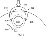
- Figures 5, 6 and 7 show a further example of a planet pin 522 and carrier 510 arrangement in which the pins 522 are received in the pin apertures 523.
- planet pin 522 having a hollow tubular body with inner 544 and outer 546 surfaces defined by a tube wall 548, and an end face 550 having circumferential rim 552 extending only partially around the circumference end face.
- the rim 552 extends through an arc greater than 180 degrees on the outer surface of the wall but is generally semi-circular to provide a cup or u-shaped rim when viewed end on.
- the radial thickness of the wall is substantially constant along its length. However, the terminal ends of the rim taper in from the inner surface of the wall to provide the radially inner surface of the rim 552 with a substantially u-shaped hollow into which a projection can be slidingly received.
- Figure 6 shows a carrier 510 having an annular projection 536 extending in from the inner surface of the axial wall 518 towards the centre of the carrier 510.
- the projection 536 is in the form of a rib having radial depth and axial length and is similar to the one described in connection with Figure 4 .
- Figure 7 shows the assembly of the pin 522 shown in Figure 5 , with the carrier 510 shown in Figure 6 .
- the pin 522 is presented to the carrier projection 536 from a radially outwards direction and slid between the axial end walls 518 of the carrier 510.
- the rib 552 of the pin includes a u-shape, the open end of which is faced radially inwards so that the projection can be received therein.
- a locking mechanism such as a bolt or key can be inserted to prevent any in service rotation of the planet pin.
Landscapes
- Engineering & Computer Science (AREA)
- General Engineering & Computer Science (AREA)
- Mechanical Engineering (AREA)
- Retarders (AREA)
Claims (15)
- Planetenträger (410), der um eine Trägerachse (411) drehbar ist, umfassend:einen Planetenbolzen (422) zum Aufnehmen eines Planetenrads (412), wobei der Planetenbolzen einen Körper mit einer Außenfläche zum Aufnehmen eines Planetenradlagers oder eines Planetenrads aufweist;wobei der Träger (410) eine erste axiale Wand (418) und eine zweite axiale Wand (420) aufweist, wobei sich der Planetenbolzen dazwischen entlang einer Planetenbolzenachse (413) erstreckt;dadurch gekennzeichnet, dass jede der ersten und zweiten axialen Wand (418, 420) ein Planetenbolzen-Rückhaltemerkmal (436) aufweist, das sich an den radial inneren Oberflächen der Trägerwände (418, 420) und innerhalb einer radial äußeren oder externen Oberfläche (434) des Planetenbolzens (422) befindet, und wobei das Planetenbolzen-Rückhaltemerkmal (436) in den Planetenbolzen (422) eingreift, um eine radiale Rückhaltung des Planetenbolzens (422) bereitzustellen, wobei ein Eingriff an mindestens einem radial inneren Abschnitt des Planetenbolzens (422) in Bezug auf die Trägerachse (411) oder die Hauptachse des Getriebes bereitgestellt ist.
- Planetenträger nach Anspruch 1, wobei das Planetenbolzen-Rückhaltemerkmal ein Vorsprung ist, der sich von einer Innenfläche einer oder beider der ersten oder zweiten axialen Wand (418, 420) und zum Körper des Planetenbolzens erstreckt und eine Eingriffsfläche (437) umfasst, die von der Planetenbolzenachse radial nach außen zugewandt ist.
- Planetenträger nach Anspruch 2, wobei die Eingriffsfläche in Bezug auf die Trägerachse radial nach innen von der Planetenbolzenachse liegt.
- Planetenträger nach Anspruch 2 oder 3, wobei der Vorsprung eine bogenförmige oder ringförmige Rippe ist.
- Planetenträger nach Anspruch 4, wobei sich der Vorsprung über mindestens 180 Grad erstreckt und ein Krümmungszentrum aufweist, das konzentrisch zur Planetenbolzenachse ist.
- Planetenträger nach einem der Ansprüche 2 bis 5, bei dem der Planetenbolzen eine Endfläche mit einer oder mehreren Wänden oder Flanschen umfasst, die einen Vorsprungsaufnahmehohlraum (438) definieren, der sich in den Planetenbolzen erstreckt.
- Planetenträger nach Anspruch 6, wobei der Vorsprungsaufnahmehohlraum (438) einen umlaufenden Bolzenrand an der Endfläche des Planetenbolzens definiert.
- Planetenträger nach Anspruch 7, wobei sich der Bolzenrand an einem Umfang des Planetenbolzens befindet.
- Planetenträger nach Anspruch 7 oder 8, wobei sich der Bolzenrand nur teilweise um den Umfang des Bolzens erstreckt, wobei die Abschlussenden des Bolzenrandes eine Öffnung zum Aufnehmen des Vorsprungs bereitstellen.
- Planetenträger nach Anspruch 9, wobei der Bolzenrand U-förmig ist.
- Planetenträger nach Anspruch 9 oder 10, wobei der Planetenbolzen drehbar mit dem Vorsprung in Eingriff steht.
- Planetenträger nach Anspruch 11, wobei einer oder beide des Trägers und des Planetenbolzens einen Verriegelungsmechanismus umfassen, der eine Drehung des Planetenbolzens um die Bolzenachse verhindert, sobald der Planetenbolzen mit dem Planetenbolzen-Rückhaltemerkmal in Eingriff steht.
- Planetenträger nach einem der vorhergehenden Ansprüche, wobei der Träger eine Anordnung eines die erste axiale Wand umfassenden ersten Teils und eines die zweite axiale Wand umfassenden zweiten Teils umfasst.
- Planetenträger nach einem der vorhergehenden Ansprüche, ferner umfassend eine Planetenbolzen-Axialklemme, die sich durch den Planetenbolzen erstreckt und angeordnet ist, um die Trennung der ersten und zweiten axialen Wand zu verhindern.
- Gasturbinentriebwerk, umfassend einen Planetengetriebezug, der den Planetenträger nach einem der Ansprüche 1 bis 14 aufweist.
Applications Claiming Priority (1)
| Application Number | Priority Date | Filing Date | Title |
|---|---|---|---|
| GBGB1614366.1A GB201614366D0 (en) | 2016-08-23 | 2016-08-23 | A mounting arrangement for a planet gear |
Publications (2)
| Publication Number | Publication Date |
|---|---|
| EP3293422A1 EP3293422A1 (de) | 2018-03-14 |
| EP3293422B1 true EP3293422B1 (de) | 2020-10-21 |
Family
ID=57045593
Family Applications (1)
| Application Number | Title | Priority Date | Filing Date |
|---|---|---|---|
| EP17186802.9A Active EP3293422B1 (de) | 2016-08-23 | 2017-08-18 | Montageanordnung für planetengetriebe |
Country Status (3)
| Country | Link |
|---|---|
| US (1) | US10422420B2 (de) |
| EP (1) | EP3293422B1 (de) |
| GB (1) | GB201614366D0 (de) |
Families Citing this family (2)
| Publication number | Priority date | Publication date | Assignee | Title |
|---|---|---|---|---|
| DE102018106693B4 (de) * | 2018-03-21 | 2023-06-15 | Rolls-Royce Deutschland Ltd & Co Kg | Gasturbinentriebwerk für ein Luftfahrzeug und Planetengetriebe |
| CN112682502B (zh) * | 2020-12-30 | 2025-02-07 | 南京高精齿轮集团有限公司 | 一种行星架的结构设计方法及行星架 |
Family Cites Families (18)
| Publication number | Priority date | Publication date | Assignee | Title |
|---|---|---|---|---|
| US2382846A (en) * | 1943-07-03 | 1945-08-14 | Bell Telephone Labor Inc | Differential gearing |
| US2501034A (en) * | 1946-09-17 | 1950-03-21 | Northrop Hendy Co | Epicyclic gear |
| GB1448059A (en) * | 1974-04-18 | 1976-09-02 | Vickers Ltd | Gears |
| DE2652652C3 (de) * | 1976-11-19 | 1981-04-09 | Daimler-Benz Ag, 7000 Stuttgart | Axialsicherung für die Planetenbolzen von Planetenräderwechselgetrieben |
| US4762024A (en) * | 1985-07-30 | 1988-08-09 | Dana Corporation | Shaft retaining means for a differential gear assembly |
| US4756212A (en) * | 1987-01-12 | 1988-07-12 | General Motors Corporation | Planet gear carrier assembly |
| US4898482A (en) * | 1987-06-04 | 1990-02-06 | Stewart Matthew M | Replaceable shim |
| DE10309666A1 (de) | 2003-03-06 | 2004-12-09 | Ina-Schaeffler Kg | Lagefixierung eines Planetenradbolzens |
| DE602006011904D1 (de) * | 2005-08-01 | 2010-03-11 | Timken Co | Epizyklisches antriebssystem mit flexpins |
| US7490460B2 (en) * | 2005-10-19 | 2009-02-17 | General Electric Company | Gas turbine engine assembly and methods of assembling same |
| KR100941713B1 (ko) * | 2007-10-19 | 2010-02-12 | 현대자동차주식회사 | 피니언 샤프트와 캐리어를 구비한 유성기어세트 |
| US8480527B2 (en) | 2008-08-27 | 2013-07-09 | Rolls-Royce Corporation | Gearing arrangement |
| JP5861916B2 (ja) * | 2011-02-01 | 2016-02-16 | 株式会社リコー | 遊星歯車装置および画像形成装置 |
| US8550957B2 (en) | 2011-06-08 | 2013-10-08 | General Electric Company | Gear system and method for using same |
| CN203258045U (zh) | 2013-05-03 | 2013-10-30 | 杭州前进齿轮箱集团股份有限公司 | 一种柔性行星销轴均载装置 |
| DE102013216795A1 (de) | 2013-08-23 | 2015-02-26 | Schaeffler Technologies Gmbh & Co. Kg | Planetentrieb mit einem Planetenträger, Planetenbolzen und mit auf den Planetenbolzen drehbar gelagerten Planetenrädern |
| DE102014200808A1 (de) | 2014-01-17 | 2015-07-23 | Zf Friedrichshafen Ag | Bolzensitz mit Schlupf |
| DE102015207114A1 (de) | 2014-05-14 | 2015-11-19 | Schaeffler Technologies AG & Co. KG | Planetenbolzen zur Schmierung von Planetenradlagern |
-
2016
- 2016-08-23 GB GBGB1614366.1A patent/GB201614366D0/en not_active Ceased
-
2017
- 2017-08-18 EP EP17186802.9A patent/EP3293422B1/de active Active
- 2017-08-18 US US15/680,613 patent/US10422420B2/en active Active
Non-Patent Citations (1)
| Title |
|---|
| None * |
Also Published As
| Publication number | Publication date |
|---|---|
| EP3293422A1 (de) | 2018-03-14 |
| US10422420B2 (en) | 2019-09-24 |
| US20180058571A1 (en) | 2018-03-01 |
| GB201614366D0 (en) | 2016-10-05 |
Similar Documents
| Publication | Publication Date | Title |
|---|---|---|
| US12480427B2 (en) | Turbomachine module equipped with variable pitch vanes and an annular interface shroud | |
| EP3179137B1 (de) | Leistungsgetriebe-stiftanordnung | |
| EP3029358B1 (de) | Leichter und nachgiebiger lagerzapfen | |
| US9353690B2 (en) | Interface with mount features for precise alignment | |
| US11859509B2 (en) | Metallic attachment system integrated into a composite structure | |
| EP2565424B1 (de) | Drehmomentrahmen und asymmetrisches Gleitlager für ein Fangetriebesystem | |
| JP5620519B2 (ja) | 航空機タービンエンジン用二重反転プロペラシステム | |
| EP3199768B1 (de) | Getriebe mit dämpfungsfeder des planentensatzes | |
| US20090155079A1 (en) | Stacked annular components for turbine engines | |
| EP3199840A1 (de) | Getriebeplanetenpressfilmdämpfer | |
| US20190186598A1 (en) | Apparatus and system for thin rim planet gear for aircraft engine power gearbox | |
| US20180347669A1 (en) | Planetary gear system and air turbine starter | |
| CN110234858B (zh) | 用于燃气涡轮发动机的锁紧螺母太阳齿轮 | |
| EP3276153B1 (de) | Gasturbine mit eine sonnenradantriebsanordnung bestehend aus mehreren verschachtelten wellen | |
| US20170191548A1 (en) | Apparatus and system for thin rim planet gear for aircraft engine power gearbox | |
| EP3293422B1 (de) | Montageanordnung für planetengetriebe | |
| EP3246517B1 (de) | Befestigungselementöffnungen zur spannungsverteilung | |
| US10400678B2 (en) | Apparatus and system for light-weight, flexible double-helical gear | |
| EP3273093B1 (de) | Ringradanordnung | |
| US11060419B2 (en) | Planetary gear drive and aircraft gas turbine with a planetary gear drive | |
| EP3800373B1 (de) | Gehäuseanordnung eines planetengetriebesystems | |
| EP3418618B1 (de) | Fitting mit mittlerem gewinde | |
| US11852080B1 (en) | Gearbox assembly | |
| CN111609093A (zh) | 飞行器发动机动力齿轮箱的薄缘行星齿轮的设备和系统 | |
| US20260117707A1 (en) | Turbine engine gearbox assembly |
Legal Events
| Date | Code | Title | Description |
|---|---|---|---|
| PUAI | Public reference made under article 153(3) epc to a published international application that has entered the european phase |
Free format text: ORIGINAL CODE: 0009012 |
|
| STAA | Information on the status of an ep patent application or granted ep patent |
Free format text: STATUS: THE APPLICATION HAS BEEN PUBLISHED |
|
| AK | Designated contracting states |
Kind code of ref document: A1 Designated state(s): AL AT BE BG CH CY CZ DE DK EE ES FI FR GB GR HR HU IE IS IT LI LT LU LV MC MK MT NL NO PL PT RO RS SE SI SK SM TR |
|
| AX | Request for extension of the european patent |
Extension state: BA ME |
|
| STAA | Information on the status of an ep patent application or granted ep patent |
Free format text: STATUS: REQUEST FOR EXAMINATION WAS MADE |
|
| 17P | Request for examination filed |
Effective date: 20180911 |
|
| RBV | Designated contracting states (corrected) |
Designated state(s): AL AT BE BG CH CY CZ DE DK EE ES FI FR GB GR HR HU IE IS IT LI LT LU LV MC MK MT NL NO PL PT RO RS SE SI SK SM TR |
|
| STAA | Information on the status of an ep patent application or granted ep patent |
Free format text: STATUS: EXAMINATION IS IN PROGRESS |
|
| 17Q | First examination report despatched |
Effective date: 20191119 |
|
| RAP1 | Party data changed (applicant data changed or rights of an application transferred) |
Owner name: ROLLS-ROYCE PLC |
|
| GRAP | Despatch of communication of intention to grant a patent |
Free format text: ORIGINAL CODE: EPIDOSNIGR1 |
|
| STAA | Information on the status of an ep patent application or granted ep patent |
Free format text: STATUS: GRANT OF PATENT IS INTENDED |
|
| INTG | Intention to grant announced |
Effective date: 20200716 |
|
| GRAS | Grant fee paid |
Free format text: ORIGINAL CODE: EPIDOSNIGR3 |
|
| GRAA | (expected) grant |
Free format text: ORIGINAL CODE: 0009210 |
|
| STAA | Information on the status of an ep patent application or granted ep patent |
Free format text: STATUS: THE PATENT HAS BEEN GRANTED |
|
| AK | Designated contracting states |
Kind code of ref document: B1 Designated state(s): AL AT BE BG CH CY CZ DE DK EE ES FI FR GB GR HR HU IE IS IT LI LT LU LV MC MK MT NL NO PL PT RO RS SE SI SK SM TR |
|
| REG | Reference to a national code |
Ref country code: GB Ref legal event code: FG4D |
|
| REG | Reference to a national code |
Ref country code: CH Ref legal event code: EP |
|
| REG | Reference to a national code |
Ref country code: IE Ref legal event code: FG4D |
|
| REG | Reference to a national code |
Ref country code: DE Ref legal event code: R096 Ref document number: 602017025748 Country of ref document: DE |
|
| REG | Reference to a national code |
Ref country code: AT Ref legal event code: REF Ref document number: 1326156 Country of ref document: AT Kind code of ref document: T Effective date: 20201115 |
|
| REG | Reference to a national code |
Ref country code: AT Ref legal event code: MK05 Ref document number: 1326156 Country of ref document: AT Kind code of ref document: T Effective date: 20201021 |
|
| REG | Reference to a national code |
Ref country code: NL Ref legal event code: MP Effective date: 20201021 |
|
| PG25 | Lapsed in a contracting state [announced via postgrant information from national office to epo] |
Ref country code: GR Free format text: LAPSE BECAUSE OF FAILURE TO SUBMIT A TRANSLATION OF THE DESCRIPTION OR TO PAY THE FEE WITHIN THE PRESCRIBED TIME-LIMIT Effective date: 20210122 Ref country code: FI Free format text: LAPSE BECAUSE OF FAILURE TO SUBMIT A TRANSLATION OF THE DESCRIPTION OR TO PAY THE FEE WITHIN THE PRESCRIBED TIME-LIMIT Effective date: 20201021 Ref country code: RS Free format text: LAPSE BECAUSE OF FAILURE TO SUBMIT A TRANSLATION OF THE DESCRIPTION OR TO PAY THE FEE WITHIN THE PRESCRIBED TIME-LIMIT Effective date: 20201021 Ref country code: PT Free format text: LAPSE BECAUSE OF FAILURE TO SUBMIT A TRANSLATION OF THE DESCRIPTION OR TO PAY THE FEE WITHIN THE PRESCRIBED TIME-LIMIT Effective date: 20210222 Ref country code: NL Free format text: LAPSE BECAUSE OF FAILURE TO SUBMIT A TRANSLATION OF THE DESCRIPTION OR TO PAY THE FEE WITHIN THE PRESCRIBED TIME-LIMIT Effective date: 20201021 Ref country code: NO Free format text: LAPSE BECAUSE OF FAILURE TO SUBMIT A TRANSLATION OF THE DESCRIPTION OR TO PAY THE FEE WITHIN THE PRESCRIBED TIME-LIMIT Effective date: 20210121 |
|
| REG | Reference to a national code |
Ref country code: LT Ref legal event code: MG4D |
|
| PG25 | Lapsed in a contracting state [announced via postgrant information from national office to epo] |
Ref country code: SE Free format text: LAPSE BECAUSE OF FAILURE TO SUBMIT A TRANSLATION OF THE DESCRIPTION OR TO PAY THE FEE WITHIN THE PRESCRIBED TIME-LIMIT Effective date: 20201021 Ref country code: BG Free format text: LAPSE BECAUSE OF FAILURE TO SUBMIT A TRANSLATION OF THE DESCRIPTION OR TO PAY THE FEE WITHIN THE PRESCRIBED TIME-LIMIT Effective date: 20210121 Ref country code: PL Free format text: LAPSE BECAUSE OF FAILURE TO SUBMIT A TRANSLATION OF THE DESCRIPTION OR TO PAY THE FEE WITHIN THE PRESCRIBED TIME-LIMIT Effective date: 20201021 Ref country code: IS Free format text: LAPSE BECAUSE OF FAILURE TO SUBMIT A TRANSLATION OF THE DESCRIPTION OR TO PAY THE FEE WITHIN THE PRESCRIBED TIME-LIMIT Effective date: 20210221 Ref country code: LV Free format text: LAPSE BECAUSE OF FAILURE TO SUBMIT A TRANSLATION OF THE DESCRIPTION OR TO PAY THE FEE WITHIN THE PRESCRIBED TIME-LIMIT Effective date: 20201021 Ref country code: ES Free format text: LAPSE BECAUSE OF FAILURE TO SUBMIT A TRANSLATION OF THE DESCRIPTION OR TO PAY THE FEE WITHIN THE PRESCRIBED TIME-LIMIT Effective date: 20201021 Ref country code: AT Free format text: LAPSE BECAUSE OF FAILURE TO SUBMIT A TRANSLATION OF THE DESCRIPTION OR TO PAY THE FEE WITHIN THE PRESCRIBED TIME-LIMIT Effective date: 20201021 |
|
| PG25 | Lapsed in a contracting state [announced via postgrant information from national office to epo] |
Ref country code: HR Free format text: LAPSE BECAUSE OF FAILURE TO SUBMIT A TRANSLATION OF THE DESCRIPTION OR TO PAY THE FEE WITHIN THE PRESCRIBED TIME-LIMIT Effective date: 20201021 |
|
| REG | Reference to a national code |
Ref country code: DE Ref legal event code: R097 Ref document number: 602017025748 Country of ref document: DE |
|
| PG25 | Lapsed in a contracting state [announced via postgrant information from national office to epo] |
Ref country code: RO Free format text: LAPSE BECAUSE OF FAILURE TO SUBMIT A TRANSLATION OF THE DESCRIPTION OR TO PAY THE FEE WITHIN THE PRESCRIBED TIME-LIMIT Effective date: 20201021 Ref country code: SK Free format text: LAPSE BECAUSE OF FAILURE TO SUBMIT A TRANSLATION OF THE DESCRIPTION OR TO PAY THE FEE WITHIN THE PRESCRIBED TIME-LIMIT Effective date: 20201021 Ref country code: SM Free format text: LAPSE BECAUSE OF FAILURE TO SUBMIT A TRANSLATION OF THE DESCRIPTION OR TO PAY THE FEE WITHIN THE PRESCRIBED TIME-LIMIT Effective date: 20201021 Ref country code: LT Free format text: LAPSE BECAUSE OF FAILURE TO SUBMIT A TRANSLATION OF THE DESCRIPTION OR TO PAY THE FEE WITHIN THE PRESCRIBED TIME-LIMIT Effective date: 20201021 Ref country code: CZ Free format text: LAPSE BECAUSE OF FAILURE TO SUBMIT A TRANSLATION OF THE DESCRIPTION OR TO PAY THE FEE WITHIN THE PRESCRIBED TIME-LIMIT Effective date: 20201021 Ref country code: EE Free format text: LAPSE BECAUSE OF FAILURE TO SUBMIT A TRANSLATION OF THE DESCRIPTION OR TO PAY THE FEE WITHIN THE PRESCRIBED TIME-LIMIT Effective date: 20201021 |
|
| PLBE | No opposition filed within time limit |
Free format text: ORIGINAL CODE: 0009261 |
|
| STAA | Information on the status of an ep patent application or granted ep patent |
Free format text: STATUS: NO OPPOSITION FILED WITHIN TIME LIMIT |
|
| PG25 | Lapsed in a contracting state [announced via postgrant information from national office to epo] |
Ref country code: DK Free format text: LAPSE BECAUSE OF FAILURE TO SUBMIT A TRANSLATION OF THE DESCRIPTION OR TO PAY THE FEE WITHIN THE PRESCRIBED TIME-LIMIT Effective date: 20201021 |
|
| 26N | No opposition filed |
Effective date: 20210722 |
|
| PG25 | Lapsed in a contracting state [announced via postgrant information from national office to epo] |
Ref country code: IT Free format text: LAPSE BECAUSE OF FAILURE TO SUBMIT A TRANSLATION OF THE DESCRIPTION OR TO PAY THE FEE WITHIN THE PRESCRIBED TIME-LIMIT Effective date: 20201021 Ref country code: AL Free format text: LAPSE BECAUSE OF FAILURE TO SUBMIT A TRANSLATION OF THE DESCRIPTION OR TO PAY THE FEE WITHIN THE PRESCRIBED TIME-LIMIT Effective date: 20201021 |
|
| PG25 | Lapsed in a contracting state [announced via postgrant information from national office to epo] |
Ref country code: SI Free format text: LAPSE BECAUSE OF FAILURE TO SUBMIT A TRANSLATION OF THE DESCRIPTION OR TO PAY THE FEE WITHIN THE PRESCRIBED TIME-LIMIT Effective date: 20201021 |
|
| REG | Reference to a national code |
Ref country code: CH Ref legal event code: PL |
|
| PG25 | Lapsed in a contracting state [announced via postgrant information from national office to epo] |
Ref country code: MC Free format text: LAPSE BECAUSE OF FAILURE TO SUBMIT A TRANSLATION OF THE DESCRIPTION OR TO PAY THE FEE WITHIN THE PRESCRIBED TIME-LIMIT Effective date: 20201021 |
|
| REG | Reference to a national code |
Ref country code: BE Ref legal event code: MM Effective date: 20210831 |
|
| PG25 | Lapsed in a contracting state [announced via postgrant information from national office to epo] |
Ref country code: LI Free format text: LAPSE BECAUSE OF NON-PAYMENT OF DUE FEES Effective date: 20210831 Ref country code: CH Free format text: LAPSE BECAUSE OF NON-PAYMENT OF DUE FEES Effective date: 20210831 |
|
| PG25 | Lapsed in a contracting state [announced via postgrant information from national office to epo] |
Ref country code: IS Free format text: LAPSE BECAUSE OF FAILURE TO SUBMIT A TRANSLATION OF THE DESCRIPTION OR TO PAY THE FEE WITHIN THE PRESCRIBED TIME-LIMIT Effective date: 20210221 Ref country code: LU Free format text: LAPSE BECAUSE OF NON-PAYMENT OF DUE FEES Effective date: 20210818 |
|
| PG25 | Lapsed in a contracting state [announced via postgrant information from national office to epo] |
Ref country code: IE Free format text: LAPSE BECAUSE OF NON-PAYMENT OF DUE FEES Effective date: 20210818 Ref country code: BE Free format text: LAPSE BECAUSE OF NON-PAYMENT OF DUE FEES Effective date: 20210831 |
|
| PG25 | Lapsed in a contracting state [announced via postgrant information from national office to epo] |
Ref country code: HU Free format text: LAPSE BECAUSE OF FAILURE TO SUBMIT A TRANSLATION OF THE DESCRIPTION OR TO PAY THE FEE WITHIN THE PRESCRIBED TIME-LIMIT; INVALID AB INITIO Effective date: 20170818 |
|
| PG25 | Lapsed in a contracting state [announced via postgrant information from national office to epo] |
Ref country code: CY Free format text: LAPSE BECAUSE OF FAILURE TO SUBMIT A TRANSLATION OF THE DESCRIPTION OR TO PAY THE FEE WITHIN THE PRESCRIBED TIME-LIMIT Effective date: 20201021 |
|
| P01 | Opt-out of the competence of the unified patent court (upc) registered |
Effective date: 20230528 |
|
| PG25 | Lapsed in a contracting state [announced via postgrant information from national office to epo] |
Ref country code: MK Free format text: LAPSE BECAUSE OF FAILURE TO SUBMIT A TRANSLATION OF THE DESCRIPTION OR TO PAY THE FEE WITHIN THE PRESCRIBED TIME-LIMIT Effective date: 20201021 |
|
| PG25 | Lapsed in a contracting state [announced via postgrant information from national office to epo] |
Ref country code: TR Free format text: LAPSE BECAUSE OF FAILURE TO SUBMIT A TRANSLATION OF THE DESCRIPTION OR TO PAY THE FEE WITHIN THE PRESCRIBED TIME-LIMIT Effective date: 20201021 |
|
| PG25 | Lapsed in a contracting state [announced via postgrant information from national office to epo] |
Ref country code: MT Free format text: LAPSE BECAUSE OF FAILURE TO SUBMIT A TRANSLATION OF THE DESCRIPTION OR TO PAY THE FEE WITHIN THE PRESCRIBED TIME-LIMIT Effective date: 20201021 |
|
| PGFP | Annual fee paid to national office [announced via postgrant information from national office to epo] |
Ref country code: DE Payment date: 20250827 Year of fee payment: 9 |
|
| PGFP | Annual fee paid to national office [announced via postgrant information from national office to epo] |
Ref country code: GB Payment date: 20250826 Year of fee payment: 9 |
|
| PGFP | Annual fee paid to national office [announced via postgrant information from national office to epo] |
Ref country code: FR Payment date: 20250825 Year of fee payment: 9 |