EP3293424B1 - Appareil d'étanchéité - Google Patents
Appareil d'étanchéité Download PDFInfo
- Publication number
- EP3293424B1 EP3293424B1 EP16792625.2A EP16792625A EP3293424B1 EP 3293424 B1 EP3293424 B1 EP 3293424B1 EP 16792625 A EP16792625 A EP 16792625A EP 3293424 B1 EP3293424 B1 EP 3293424B1
- Authority
- EP
- European Patent Office
- Prior art keywords
- sealing apparatus
- grease
- inclined surface
- seal
- axis
- Prior art date
- Legal status (The legal status is an assumption and is not a legal conclusion. Google has not performed a legal analysis and makes no representation as to the accuracy of the status listed.)
- Active
Links
Images

Classifications
-
- F—MECHANICAL ENGINEERING; LIGHTING; HEATING; WEAPONS; BLASTING
- F16—ENGINEERING ELEMENTS AND UNITS; GENERAL MEASURES FOR PRODUCING AND MAINTAINING EFFECTIVE FUNCTIONING OF MACHINES OR INSTALLATIONS; THERMAL INSULATION IN GENERAL
- F16J—PISTONS; CYLINDERS; SEALINGS
- F16J15/00—Sealings
- F16J15/16—Sealings between relatively-moving surfaces
- F16J15/32—Sealings between relatively-moving surfaces with elastic sealings, e.g. O-rings
- F16J15/3204—Sealings between relatively-moving surfaces with elastic sealings, e.g. O-rings with at least one lip
- F16J15/3232—Sealings between relatively-moving surfaces with elastic sealings, e.g. O-rings with at least one lip having two or more lips
-
- F—MECHANICAL ENGINEERING; LIGHTING; HEATING; WEAPONS; BLASTING
- F16—ENGINEERING ELEMENTS AND UNITS; GENERAL MEASURES FOR PRODUCING AND MAINTAINING EFFECTIVE FUNCTIONING OF MACHINES OR INSTALLATIONS; THERMAL INSULATION IN GENERAL
- F16J—PISTONS; CYLINDERS; SEALINGS
- F16J15/00—Sealings
- F16J15/16—Sealings between relatively-moving surfaces
- F16J15/32—Sealings between relatively-moving surfaces with elastic sealings, e.g. O-rings
- F16J15/3204—Sealings between relatively-moving surfaces with elastic sealings, e.g. O-rings with at least one lip
-
- C—CHEMISTRY; METALLURGY
- C10—PETROLEUM, GAS OR COKE INDUSTRIES; TECHNICAL GASES CONTAINING CARBON MONOXIDE; FUELS; LUBRICANTS; PEAT
- C10M—LUBRICATING COMPOSITIONS; USE OF CHEMICAL SUBSTANCES EITHER ALONE OR AS LUBRICATING INGREDIENTS IN A LUBRICATING COMPOSITION
- C10M169/00—Lubricating compositions characterised by containing as components a mixture of at least two types of ingredient selected from base-materials, thickeners or additives, covered by the preceding groups, each of these compounds being essential
- C10M169/02—Mixtures of base-materials and thickeners
-
- F—MECHANICAL ENGINEERING; LIGHTING; HEATING; WEAPONS; BLASTING
- F02—COMBUSTION ENGINES; HOT-GAS OR COMBUSTION-PRODUCT ENGINE PLANTS
- F02F—CYLINDERS, PISTONS OR CASINGS, FOR COMBUSTION ENGINES; ARRANGEMENTS OF SEALINGS IN COMBUSTION ENGINES
- F02F11/00—Arrangements of sealings in combustion engines
-
- F—MECHANICAL ENGINEERING; LIGHTING; HEATING; WEAPONS; BLASTING
- F02—COMBUSTION ENGINES; HOT-GAS OR COMBUSTION-PRODUCT ENGINE PLANTS
- F02F—CYLINDERS, PISTONS OR CASINGS, FOR COMBUSTION ENGINES; ARRANGEMENTS OF SEALINGS IN COMBUSTION ENGINES
- F02F7/00—Casings, e.g. crankcases
-
- F—MECHANICAL ENGINEERING; LIGHTING; HEATING; WEAPONS; BLASTING
- F16—ENGINEERING ELEMENTS AND UNITS; GENERAL MEASURES FOR PRODUCING AND MAINTAINING EFFECTIVE FUNCTIONING OF MACHINES OR INSTALLATIONS; THERMAL INSULATION IN GENERAL
- F16J—PISTONS; CYLINDERS; SEALINGS
- F16J15/00—Sealings
- F16J15/16—Sealings between relatively-moving surfaces
- F16J15/32—Sealings between relatively-moving surfaces with elastic sealings, e.g. O-rings
- F16J15/324—Arrangements for lubrication or cooling of the sealing itself
-
- F—MECHANICAL ENGINEERING; LIGHTING; HEATING; WEAPONS; BLASTING
- F16—ENGINEERING ELEMENTS AND UNITS; GENERAL MEASURES FOR PRODUCING AND MAINTAINING EFFECTIVE FUNCTIONING OF MACHINES OR INSTALLATIONS; THERMAL INSULATION IN GENERAL
- F16J—PISTONS; CYLINDERS; SEALINGS
- F16J15/00—Sealings
- F16J15/16—Sealings between relatively-moving surfaces
- F16J15/32—Sealings between relatively-moving surfaces with elastic sealings, e.g. O-rings
- F16J15/3244—Sealings between relatively-moving surfaces with elastic sealings, e.g. O-rings with hydrodynamic pumping action
-
- C—CHEMISTRY; METALLURGY
- C10—PETROLEUM, GAS OR COKE INDUSTRIES; TECHNICAL GASES CONTAINING CARBON MONOXIDE; FUELS; LUBRICANTS; PEAT
- C10M—LUBRICATING COMPOSITIONS; USE OF CHEMICAL SUBSTANCES EITHER ALONE OR AS LUBRICATING INGREDIENTS IN A LUBRICATING COMPOSITION
- C10M2203/00—Organic non-macromolecular hydrocarbon compounds and hydrocarbon fractions as ingredients in lubricant compositions
- C10M2203/10—Petroleum or coal fractions, e.g. tars, solvents, bitumen
- C10M2203/102—Aliphatic fractions
- C10M2203/1025—Aliphatic fractions used as base material
-
- C—CHEMISTRY; METALLURGY
- C10—PETROLEUM, GAS OR COKE INDUSTRIES; TECHNICAL GASES CONTAINING CARBON MONOXIDE; FUELS; LUBRICANTS; PEAT
- C10M—LUBRICATING COMPOSITIONS; USE OF CHEMICAL SUBSTANCES EITHER ALONE OR AS LUBRICATING INGREDIENTS IN A LUBRICATING COMPOSITION
- C10M2205/00—Organic macromolecular hydrocarbon compounds or fractions, whether or not modified by oxidation as ingredients in lubricant compositions
- C10M2205/02—Organic macromolecular hydrocarbon compounds or fractions, whether or not modified by oxidation as ingredients in lubricant compositions containing acyclic monomers
- C10M2205/028—Organic macromolecular hydrocarbon compounds or fractions, whether or not modified by oxidation as ingredients in lubricant compositions containing acyclic monomers containing aliphatic monomers having more than four carbon atoms
- C10M2205/0285—Organic macromolecular hydrocarbon compounds or fractions, whether or not modified by oxidation as ingredients in lubricant compositions containing acyclic monomers containing aliphatic monomers having more than four carbon atoms used as base material
-
- C—CHEMISTRY; METALLURGY
- C10—PETROLEUM, GAS OR COKE INDUSTRIES; TECHNICAL GASES CONTAINING CARBON MONOXIDE; FUELS; LUBRICANTS; PEAT
- C10M—LUBRICATING COMPOSITIONS; USE OF CHEMICAL SUBSTANCES EITHER ALONE OR AS LUBRICATING INGREDIENTS IN A LUBRICATING COMPOSITION
- C10M2207/00—Organic non-macromolecular hydrocarbon compounds containing hydrogen, carbon and oxygen as ingredients in lubricant compositions
- C10M2207/10—Carboxylix acids; Neutral salts thereof
- C10M2207/12—Carboxylix acids; Neutral salts thereof having carboxyl groups bound to acyclic or cycloaliphatic carbon atoms
- C10M2207/125—Carboxylix acids; Neutral salts thereof having carboxyl groups bound to acyclic or cycloaliphatic carbon atoms having hydrocarbon chains of eight up to twenty-nine carbon atoms, i.e. fatty acids
- C10M2207/1256—Carboxylix acids; Neutral salts thereof having carboxyl groups bound to acyclic or cycloaliphatic carbon atoms having hydrocarbon chains of eight up to twenty-nine carbon atoms, i.e. fatty acids used as thickening agent
-
- C—CHEMISTRY; METALLURGY
- C10—PETROLEUM, GAS OR COKE INDUSTRIES; TECHNICAL GASES CONTAINING CARBON MONOXIDE; FUELS; LUBRICANTS; PEAT
- C10N—INDEXING SCHEME ASSOCIATED WITH SUBCLASS C10M RELATING TO LUBRICATING COMPOSITIONS
- C10N2020/00—Specified physical or chemical properties or characteristics, i.e. function, of component of lubricating compositions
- C10N2020/01—Physico-chemical properties
- C10N2020/02—Viscosity; Viscosity index
-
- C—CHEMISTRY; METALLURGY
- C10—PETROLEUM, GAS OR COKE INDUSTRIES; TECHNICAL GASES CONTAINING CARBON MONOXIDE; FUELS; LUBRICANTS; PEAT
- C10N—INDEXING SCHEME ASSOCIATED WITH SUBCLASS C10M RELATING TO LUBRICATING COMPOSITIONS
- C10N2030/00—Specified physical or chemical properties which is improved by the additive characterising the lubricating composition, e.g. multifunctional additives
- C10N2030/06—Oiliness; Film-strength; Anti-wear; Resistance to extreme pressure
-
- C—CHEMISTRY; METALLURGY
- C10—PETROLEUM, GAS OR COKE INDUSTRIES; TECHNICAL GASES CONTAINING CARBON MONOXIDE; FUELS; LUBRICANTS; PEAT
- C10N—INDEXING SCHEME ASSOCIATED WITH SUBCLASS C10M RELATING TO LUBRICATING COMPOSITIONS
- C10N2030/00—Specified physical or chemical properties which is improved by the additive characterising the lubricating composition, e.g. multifunctional additives
- C10N2030/36—Seal compatibility, e.g. with rubber
-
- C—CHEMISTRY; METALLURGY
- C10—PETROLEUM, GAS OR COKE INDUSTRIES; TECHNICAL GASES CONTAINING CARBON MONOXIDE; FUELS; LUBRICANTS; PEAT
- C10N—INDEXING SCHEME ASSOCIATED WITH SUBCLASS C10M RELATING TO LUBRICATING COMPOSITIONS
- C10N2040/00—Specified use or application for which the lubricating composition is intended
- C10N2040/02—Bearings
-
- C—CHEMISTRY; METALLURGY
- C10—PETROLEUM, GAS OR COKE INDUSTRIES; TECHNICAL GASES CONTAINING CARBON MONOXIDE; FUELS; LUBRICANTS; PEAT
- C10N—INDEXING SCHEME ASSOCIATED WITH SUBCLASS C10M RELATING TO LUBRICATING COMPOSITIONS
- C10N2050/00—Form in which the lubricant is applied to the material being lubricated
- C10N2050/10—Form in which the lubricant is applied to the material being lubricated semi-solid; greasy
Definitions
- the present invention relates to a sealing apparatus, and particularly relates to a sealing apparatus suitably usable for an internal combustion engine of a vehicle or a general-purpose machine in a low temperature environment.
- a sealing apparatus has been used in an engine of a vehicle such as an automobile to seal a gap between two mutually relatively rotating members.
- the sealing apparatus is used to seal a gap between a rotating shaft such as a crankshaft and a casing through which this shaft is inserted.
- a seal lip portion of the sealing apparatus contacts the shaft, and then, a sealed space is formed in the casing.
- engine oil as a fluid to be sealed acts as a lubricant.
- the sealed fluid acts as a lubricant to thereby suppress wear of the seal lip portion of the sealing apparatus.
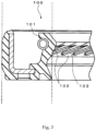
- Fig. 3 is a diagram illustrating a schematic configuration of a conventional sealing apparatus.
- a conventional sealing apparatus 100 at an atmospheric side inclined surface 102 on the opposite side of a sealed fluid side in the seal lip portion 101, a plurality of projections (screw projections 103) extending obliquely with respect to an axis and arranged at equal intervals.
- the screw projections 103 act as a screw pump to prevent the sealed fluid from leaking to an atmospheric side.
- US 2002/0012485 A1 discloses a sealed crankshaft bearing assembly for a two-stroke engine.
- the assembly includes a grease seal disposed between an inner races and an outer race.
- the grease seal includes a rigid support structure generally L-shaped in section, and a flexible sealing member.
- the flexible sealing member has a first and a second circumferential sealing lip as well as a chamber between the two lips that accommodates lubricant therein for lubricating the lips.
- grease or oil is used and the grease seal seals either type of lubricant.
- One specific grease that can be used for lubrication of the bearings is Kliiber Isoflex NB52, no. 004131, available from Klüber in Germany. This grease uses barium complex soap as a thickener and synthetic hydrocarbon oil as type of oil.
- Patent Literature 1 Japanese Patent Application Publication No. 2005-172061
- Patent Literature 2 US 2002/0012485 A1
- the sealed fluid does not flow when the engine starts.
- the sealed fluid does not circulate in the engine and is not supplied to the seal lip portion 101.
- the sealed fluid does not act as the lubricant for the seal lip portion 101, leading to lubrication failure of the seal lip portion 101 and progress in wear of the seal lip portion 101.
- the progress in wear of the seal lip portion 101 may result in wear of the screw projection 103 or a reduction of lip interference, which may deteriorate the pumping performance of the sealing apparatus 100 and may cause leakage of the sealed fluid.
- a sealing apparatus provides a sealing apparatus in accordance with claim 1.
- the sealing apparatus is sealing a gap between two members mutually relatively rotatable about an axis in an internal combustion engine, the sealing apparatus characterized by comprising: an elastic body portion which is an elastic body including an annular attaching portion attached to one of the two members and centered about the axis; and a seal portion in close contact with another of the two members in a manner in which the other of the two members is slidable, wherein the seal portion comprises: an annular seal lip portion centered about the axis; and an annular dust lip centered about the axis on an atmospheric side on an opposite side of a sealed fluid side with respect to the seal lip portion, wherein the seal lip portion comprises a lip tip portion which is an annular projecting body projecting toward the axis, and grease is applied to the seal lip portion, the grease contains at least one of a synthetic hydrocarbon oil and a mineral oil as a base oil and has a low temperature starting torque
- the grease is applied between the lip tip portion and the dust lip.
- the lip tip portion comprises: a sealed fluid side inclined surface which is an inclined surface on the sealed fluid side; an atmospheric side inclined surface which is an inclined surface on the atmospheric side; and a sliding surface contacting the other of the two members between the sealed fluid side inclined surface and the atmospheric side inclined surface in a manner in which the other of the two members is slidable, wherein the grease is applied to at least the sliding surface.
- the grease is applied to at least the sliding surface of the lip tip portion and the atmospheric side inclined surface.
- the grease is applied to a seal lip portion and thus can suppress wear of the seal lip portion due to sliding.
- the grease contains at least one of a synthetic hydrocarbon oil and a mineral oil as a base oil, has a low temperature starting torque of 25 N ⁇ cm or less at -30°C, and thus the fluidity of grease is high even in a low temperature environment. For this reason, in a low temperature environment, the grease is supplied to the sliding surface of the seal lip portion, thus suppressing wear of the seal lip portion in a low temperature environment. The suppression of wear of the seal lip portion can serve to prevent leakage of the sealed fluid.
- grease is applied between the lip tip portion and the dust lip, thus facilitating supply of the grease to the sliding surface of the seal lip portion and suppressing wear of the seal lip portion in a low temperature environment.
- grease is applied to at least the sliding surface of the lip tip portion, thus effectively suppressing wear of the seal lip portion in a low temperature environment.
- grease is applied to at least the sliding surface and an atmospheric side inclined surface.
- Grease is applied to the sliding surface and the grease applied to the atmospheric side inclined surface is supplied to the sliding surface of the seal lip portion, thus more continuously suppressing wear of the sliding surface in a low temperature environment.
- Fig. 1 is a sectional diagram taken along an axis of a sealing apparatus for illustrating a schematic configuration of the sealing apparatus according to an embodiment of the present invention.
- a sealing apparatus 1 includes an elastic body portion 2 made of an annular elastic body and centered about an axis x; and a reinforcing ring 3 made of an annular metal and centered about the axis x.
- the elastic body of the elastic body portion 2 include various rubber materials.
- the various rubber materials include synthetic rubbers such as nitrile rubber (NBR), hydrogenated nitrile rubber (H-NBR), acrylic rubber (ACM), or fluorine rubber (FKM).
- the metal of the reinforcing ring 3 include stainless steel or SPCC (cold rolled steel sheet).
- the sealing apparatus 1 is used to seal a gap between two members mutually relatively rotatable about the axis x.
- the elastic body portion 2 includes an attaching portion 4 fitted in an opening of a portion to be attached such as a casing or housing as one of the two mutually relatively rotatable members; and a seal portion 5 in close contact with an outer peripheral surface of the other of the two members such as a shaft to be inserted into the elastic body portion 2 in a manner in which the outer peripheral surface is slidable.
- the attaching portion 4 is a cylindrical annular portion located on an outer peripheral side of the elastic body portion 2 and centered about the axis x.
- An outer peripheral surface 41 as a peripheral surface on the outer peripheral side of the attaching portion 4 is defined based on an interference portion 42 having a thickness (radial dimension) corresponding to the dimension of the unillustrated opening of the portion to be attached.
- the term "outer side” refers to a direction of arrow a (see Fig. 1 ) in a direction of the axis x
- the term “inner side” refers to a direction of arrow b (see Fig. 1 ) in the direction of the axis x.
- the inner side refers to a direction (sealed fluid side) facing a region where the sealed fluid such as lubricating oil is present
- the outer side refers to a direction (atmospheric side) facing a region where the sealed fluid is not or should not be present
- the term "outer peripheral side” refers to a direction (direction of arrow c in Fig.1 ) away from the axis x in a direction perpendicular to the axis x
- the term “inner peripheral side” refers to a direction (direction of arrow d in Fig.1 ) approaching the axis x.
- the seal portion 5 is a cylindrical annular portion located on the inner peripheral side of the elastic body portion 2 and centered about the axis x.
- the seal portion 5 includes a seal lip portion 51 as illustrated in Fig. 1 .
- the seal portion 5 includes a dust lip portion 52 located on the outer side (atmospheric side) with respect to the seal lip portion 51.
- the dust lip portion 52 is provided to prevent foreign matter such as dust from entering a contact portion between the seal lip portion 51 and a shaft (unillustrated).
- the dust lip portion 52 is an annular member centered about the axis x and extending obliquely from an inner peripheral side end portion of the seal portion 5 toward the outer side in the inner peripheral direction.
- the seal lip portion 51 includes a lip tip portion 53 located on an inner side portion on the inner peripheral side of the seal lip portion 51.
- the lip tip portion 53 is an annular projection body whose shape of the cross section including the axis x (hereinafter may be simply referred to as a cross section) is a wedge shape projecting in the inner peripheral direction and centered about the axis x. More specifically, the lip tip portion 53 includes a sealed fluid side inclined surface 54, a sliding surface 55, and an atmospheric side inclined surface 56 in the order from the inner side (sealed fluid side).
- the above projection body is defined by the above surfaces 54 to 56.
- the sealed fluid side inclined surface 54 is an inclined surface on the sealed fluid side. Specifically, as illustrated in Fig. 1 , the sealed fluid side inclined surface 54 is an annular surface centered about the axis x and a conical surface (tapered surface) extending tapered in the direction of the axis x. The tapered surface of the sealed fluid side inclined surface 54 decreases in diameter as it progresses from the inner side toward the outer side in the direction of the axis x.
- the atmospheric side inclined surface 56 is an inclined surface on the atmospheric side. Specifically, as illustrated in Fig. 1 , the atmospheric side inclined surface 56 is an annular surface centered about the axis x and a conical surface (tapered surface) extending tapered in the direction of the axis x. The tapered surface of the atmospheric side inclined surface 56 increases in diameter as it progresses from the inner side toward the outer side in the direction of the axis x.
- the sliding surface 55 is a cylindrical surface extending between the sealed fluid side inclined surface 54 and the atmospheric side inclined surface 56 contacting the unillustrated shaft in a manner such that the shaft is slidable.
- the atmospheric side inclined surface 56 of the lip tip portion 53 includes a screw projection 57 which has a plurality of projections 58 whose tip ends reach the vicinity of the sliding surface 55.
- the plurality of projections 58 of the screw projection 57 are arranged in parallel with each other at predetermined intervals in the circumferential direction.
- the projections 58 are projections protruding in the inner peripheral direction and extending obliquely with respect to the axis x.
- the shape and size of the projection 58 are conventionally known and are not limited to the above-described shape and size.
- the lip portion 51 includes an annular recessed portion 59 located on an outer peripheral side surface facing the lip tip portion 53.
- an annular spring 6 of the sealing apparatus 1 is accommodated in the recessed portion 59. The spring 6 urges the lip tip portion 53 in the inner peripheral direction.
- the elastic body portion 2 includes a disk portion 21 having a hollow disk shape and centered about the axis x.
- the disk portion 21 connects the attaching portion 4 and the seal portion 5 at each end portion thereof on the outer side.
- the reinforcing ring 3 is an annular member having a substantially L-shaped cross section and centered about the axis x. As illustrated in Fig. 1 , the reinforcing ring 3 is partially covered with the elastic body portion 2 and is integrated with the elastic body portion 2. In the present embodiment, a part of the inner side surface of the reinforcing ring 3 is exposed without being covered with the elastic body portion 2, but a part of the reinforcing ring 3 may be covered with the elastic body portion 2 or the whole of the reinforcing ring 3 may be covered with the elastic body portion 2 as long as the reinforcing ring 3 has a structure capable of reinforcing the elastic body portion 2.
- the reinforcing ring 3 is manufactured by, for example, press working or forging, and most of the elastic body portion 2 is molded with a mold by cross-linking (vulcanization) to be described later. During the cross-linking molding, the reinforcing ring 3 is placed inside the mold, and then the elastic body portion 2 is adhered to the reinforcing ring 3 by cross-linking bonding, and then, the elastic body portion 2 is integrally molded with the reinforcing ring 3.
- cross-linking vulcanization
- grease G is applied to the seal lip portion 51.
- the grease G is applied between the lip tip portion 53 and the dust lip portion 52.
- the grease G may be applied entirely between the lip tip portion 53 and the dust lip portion 52 or may be applied partially between the lip tip portion 53 and the dust lip portion 52.
- the grease G may be applied only to the sliding surface 55 or may be applied only to the sliding surface 55 and the atmospheric side inclined surface 56.
- the grease for use in the present embodiment contains at least one of a synthetic hydrocarbon oil and a mineral oil as a base oil.
- the grease preferably contains a synthetic hydrocarbon oil as the base oil.
- synthetic hydrocarbon oils include poly- ⁇ -olefins, ethylene- ⁇ -olefin copolymers, polybutenes, alkylbenzenes, and alkylnaphthalenes.
- mineral oils include paraffinic mineral oils, olefinic mineral oils and naphthenic mineral oils. These synthetic hydrocarbon oils and mineral oils may be used singly or in mixture.
- the base oil content of the grease is preferably 60 to 90 wt%.
- the grease in addition contains a thickener selected from a group consisting of metal soaps and metal complex soaps.
- the metal soaps include lithium soaps, sodium soaps, potassium soaps, calcium soaps, barium soaps and aluminum soaps.
- the metal complex soaps include lithium complex soaps, calcium complex soaps, and barium complex soaps. These thickeners may be used singly or in mixture.
- the thickener content of the grease is preferably 5 to 50 wt%, and more preferably 10 to 40 wt%.
- the grease may further contain additives such as other thickeners, antioxidants, rust inhibitors, corrosion inhibitors, extreme pressure agents, oiliness agents, solid lubricants, conductivity improvers, and the like, as needed.
- additives such as other thickeners, antioxidants, rust inhibitors, corrosion inhibitors, extreme pressure agents, oiliness agents, solid lubricants, conductivity improvers, and the like, as needed.
- antioxidants examples include phenolic antioxidants such as 2,6-di-tert-butyl-4-methylphenol and 4,4'-methylenebis(2,6-di-tert-butylphenol); amine type antioxidants such as alkyldiphenylamines, triphenylamines, phenyl- ⁇ -naphthylamines, alkylated phenyl- ⁇ -naphthylamines, phenothiazines, alkylated phenothiazines and; furthermore, phosphoric acid type antioxidants, sulfur type antioxidants and the like.
- phenolic antioxidants such as 2,6-di-tert-butyl-4-methylphenol and 4,4'-methylenebis(2,6-di-tert-butylphenol)
- amine type antioxidants such as alkyldiphenylamines, triphenylamines, phenyl- ⁇ -naphthylamines, alkylated phenyl- ⁇ -
- rust inhibitors examples include fatty acids, fatty acid metal salts, fatty acid amines, alkylsulfonic acid metal salts, alkylsulfonic acid amine salts, oxidized paraffins, polyoxyethylene alkyl ethers, and the like.
- corrosion inhibitors examples include penzotriazoles, benzimidazoles, thiadiazoles, and the like.
- extreme pressure agents examples include phosphorus-based compounds such as phosphoric acid esters, phosphorous acid esters, and phosphoric ester amine salts; sulfur compounds such as sulfides and disulfides; sulfur-based metal salts such as dialkyldithiophosphoric acid metal salts and dialkyldithiocarbamic acid metal salts; chlorinated compounds such as chlorinated paraffins and chlorinated diphenyl; and the like.
- oiliness agents examples include fatty acids or esters thereof, higher alcohols, polyhydric alcohols or esters thereof, aliphatic esters, aliphatic amines, fatty acid monoglycerides, a montan wax, an amide-based wax, and the like.
- solid lubricants examples include molybdenum disulfide, carbon black, graphite, boron nitride, silane nitride, melamine cyanurate, and the like.
- the worked penetration of the grease is preferably 265 to 295. Note that the worked penetration is measured at 25°C based on JIS K 2220.
- the low temperature starting torque of the grease is 25 N ⁇ cm or less. Furthermore, the low temperature starting torque of the grease is preferably 12 N ⁇ cm or less. When the low temperature starting torque exceeds 25 N ⁇ cm, the fluidity decreases in a low temperature environment. This leads to insufficient action as the lubricant in an assembled state of the sealing apparatus 1 in a low temperature environment, which is not preferable because this promotes wear of the seal lip portion 51 of the sealing apparatus 1. Note that the low temperature starting torque is measured at -30°C based on JIS K2220.
- the sealing apparatus 1 according to the present embodiment is assumed to be disposed between two mutually relatively rotatable members, namely, a crankcase and a crankshaft of an automobile engine. Specifically, the sealing apparatus 1 is assumed to be disposed in a gap and to seal the gap between a shaft hole of the crankcase and the crankshaft inserted into the shaft hole. Note that the sealing apparatus 1 according to the present invention is not limited to the one disposed between a crankshaft and a crankcase of an automobile engine. The sealing apparatus 1 according to the present invention can be applied to seal a gap between two mutually relatively rotatable members in a vehicle or a general-purpose machine.
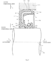
- Fig. 2 is a partial sectional diagram for illustrating the usage state of the sealing apparatus 1 according to the embodiment of the present invention.
- a crankcase 71 includes a shaft hole 72 as a cylindrical opening.
- a crankshaft 73 is inserted into the shaft hole 72.
- the sealing apparatus 1 is attached to a gap 76 and to seal the gap 76 between an inner peripheral surface 74 which is a surface on an inner periphery of the shaft hole 72 and an outer peripheral surface 75 which is a surface of the crankshaft 73. Note that the grease G has been applied to the seal lip portion 51 in advance.
- the sealing apparatus 1 is attached to the crankcase 71 such that the attaching portion 4 is fitted into the shaft hole 72 of the crankcase 71. More specifically, the interference portion 42 of the attaching portion 4 is compressed between the reinforcing ring 3 and the inner peripheral surface 74 of the shaft hole 72, and then the sealing apparatus 1 is fitted and strongly fixed to the crankcase 71.
- the outer peripheral surface 41 of the elastic body portion 2 closely contacts the inner peripheral surface 74 of the shaft hole 72 in a liquid-tight manner.
- the crankshaft 73 is inserted into the seal portion 5, and the lip tip portion 53 (sliding surface 55) of the seal lip portion 51 contacts the outer peripheral surface 75 of the shaft 73.
- the gap 76 is sealed by the fitting of the attaching portion 4 and the contacting of the lip tip portion 53.
- the sealing apparatus 1 of the embodiment of the present invention grease is applied to the seal lip portion 51 and thus the wear of the seal lip portion 51 due to sliding can be suppressed.
- the grease contains at least one of a synthetic hydrocarbon oil and a mineral oil as a base oil and the grease has a low temperature starting torque of 25 N/cm or less, and thus the fluidity of grease is high even in a low temperature environment and the effect of suppressing the wear of the seal lip portion 51 is considerable.
- the suppression of the wear of the seal lip portion 51 can prevent leakage of the sealed fluid.
- the present invention is not limited to the above embodiments of the present invention and may include all aspects included in the concept of the present invention and the scope of the claims.
- the above components may be combined appropriately and selectively to solve at least a part of the above problems and to exert at least a part of the above effects.
- the shape, material, arrangement, size, and the like of each component in the above embodiments can be appropriately changed according to a specific application of the present invention.
- the shapes of the attaching portion 4, the seal portion 5, and the reinforcing ring 3 are not limited to the above shapes.
- a rear differential side oil seal which is an acrylic rubber oil seal having an inner diameter of 37 mm was used as sealing apparatus according to present examples and comparative examples.
- greases used in the sealing apparatus according to the present examples 1 to 3 and the comparative examples 1 to 3 were listed in Table 1 to be described later.
- Lithium soap Li salt of fatty acid monocarboxylic acid having 12 to 24 carbon atoms (it is noted that one contains at least one hydrogen group or one contains no hydrogen group)
- Barium complex soap complex soap of fatty acid dicarboxylic acid and monoaminocarboxylic acid.
- the low temperature starting torque was measured according to JIS K2220 at -30°C.
- Grease was applied to a sliding surface of an acrylic rubber oil seal having an inner diameter of 37 mm and was subjected to a rotation test at -30°C.
- the rotation test was performed in a state in which a lubricating oil (mineral oil gear oil having a viscosity grade of 75 W-90 and a pour point of -23°C) was filled up to the center of the rotating shaft. 100 cycles were repeated, assuming that one cycle refers to a pattern of rotating at a low temperature of -30°C for 10 minutes in the normal rotation direction, then stopping and cooling. Then, the wear width of the sliding surface was observed with a microscope. A wear width of 0.5 mm or less was accepted, and a wear width of more than 0.5 mm was rejected.
- the grease applied to the seal lip portion contains a synthetic hydrocarbon oil as the base oil and has a low temperature starting torque of 25 N ⁇ cm or less, whereby a considerable effect of suppressing the wear of the seal lip portion is exerted even in a low temperature environment of -30°C.
Landscapes
- Engineering & Computer Science (AREA)
- General Engineering & Computer Science (AREA)
- Mechanical Engineering (AREA)
- Chemical & Material Sciences (AREA)
- Combustion & Propulsion (AREA)
- Chemical Kinetics & Catalysis (AREA)
- Fluid Mechanics (AREA)
- General Chemical & Material Sciences (AREA)
- Oil, Petroleum & Natural Gas (AREA)
- Organic Chemistry (AREA)
- Physics & Mathematics (AREA)
- Sealing With Elastic Sealing Lips (AREA)
- Sealing Devices (AREA)
Claims (6)
- Appareil d'étanchéité (1) pour assurer l'étanchéité d'un espace (76) entre deux éléments (71, 73) pouvant tourner l'un par rapport à l'autre autour d'un axe (x) dans un moteur à combustion interne, l'appareil d'étanchéité (1) comprenant :une partie de corps (2) élastique qui est un corps élastique comportant une partie de fixation (4) annulaire devant être fixée à l'un (71) des deux éléments (71, 73) et centrée autour de l'axe (x) ; et une partie d'étanchéité (5) devant être en contact étroit avec un autre (73) des deux éléments (71, 73) d'une manière dans laquelle l'autre (71) des deux éléments (71, 73) peut coulisser, dans lequella partie d'étanchéité (5) comprend : une partie lèvre d'étanchéité (51) annulaire centrée autour de l'axe (x) ; et une lèvre antipoussière (52) annulaire centrée autour de l'axe (x) sur un côté atmosphérique sur un côté opposé d'un côté fluide étanche par rapport à la partie lèvre d'étanchéité (51), dans lequella partie lèvre d'étanchéité (51) comprend une partie pointe de lèvre (53) qui est un corps saillant annulaire faisant saillie vers l'axe (x), etde la graisse est appliquée sur la partie lèvre d'étanchéité (51), la graisse, de façon à supprimer l'usure de la partie lèvre d'étanchéité (51) dans un environnement à basse température, contient au moins l'une d'une huile hydrocarbonée synthétique et d'une huile minérale en tant qu'huile de base ainsi qu'au moins un choisi dans un groupe constitué par des savons métalliques et un savon complexe métallique en tant qu'épaississant, et a un couple de démarrage à basse température de 25 N·cm ou moins à -30 °C.
- Appareil d'étanchéité (1) selon la revendication 1, caractérisé en ce que la graisse est appliquée entre la partie pointe de lèvre (53) et la lèvre antipoussière (52).
- Appareil d'étanchéité (1) selon la revendication 2, caractérisé en ce que la partie pointe de lèvre (53) comprend : une surface inclinée (54) côté fluide étanche qui est une surface inclinée destinée à être placée sur le côté fluide étanche ; une surface inclinée (56) côté atmosphérique qui est une surface inclinée destinée à être placée sur le côté atmosphérique ; et une surface de coulissement (55) pour venir en contact avec l'autre (73) des deux éléments (71, 73) entre la surface inclinée (54) côté fluide étanche et la surface inclinée (56) côté atmosphérique d'une manière dans laquelle l'autre (73) des deux éléments (71, 73) peut coulisser, dans lequel la graisse est appliquée sur au moins la surface de coulissement (55).
- Appareil d'étanchéité (1) selon la revendication 3, caractérisé en ce que la graisse est appliquée sur au moins la surface de coulissement (55) de la partie pointe de lèvre (53) et la surface inclinée (56) côté atmosphérique.
- Appareil d'étanchéité (1) selon l'une des revendications 1 à 4, caractérisé en ce que l'huile minérale est une huile minérale paraffinique.
- Appareil d'étanchéité (1) selon l'une des revendications 1 à 5, caractérisé en ce que l'huile hydrocarbonée synthétique est une poly-α-oléfine.
Applications Claiming Priority (2)
| Application Number | Priority Date | Filing Date | Title |
|---|---|---|---|
| JP2015096239 | 2015-05-11 | ||
| PCT/JP2016/063654 WO2016181900A1 (fr) | 2015-05-11 | 2016-05-06 | Dispositif d'étanchéité |
Publications (3)
| Publication Number | Publication Date |
|---|---|
| EP3293424A1 EP3293424A1 (fr) | 2018-03-14 |
| EP3293424A4 EP3293424A4 (fr) | 2019-02-13 |
| EP3293424B1 true EP3293424B1 (fr) | 2023-02-01 |
Family
ID=57248063
Family Applications (1)
| Application Number | Title | Priority Date | Filing Date |
|---|---|---|---|
| EP16792625.2A Active EP3293424B1 (fr) | 2015-05-11 | 2016-05-06 | Appareil d'étanchéité |
Country Status (7)
| Country | Link |
|---|---|
| US (1) | US10605368B2 (fr) |
| EP (1) | EP3293424B1 (fr) |
| JP (1) | JP6830060B2 (fr) |
| CN (1) | CN107532721A (fr) |
| CA (1) | CA2985453C (fr) |
| RU (1) | RU2673949C1 (fr) |
| WO (1) | WO2016181900A1 (fr) |
Families Citing this family (7)
| Publication number | Priority date | Publication date | Assignee | Title |
|---|---|---|---|---|
| CN111465788B (zh) * | 2017-12-27 | 2022-09-20 | Nok株式会社 | 密封装置 |
| CN111712659B (zh) * | 2018-07-24 | 2023-03-21 | Nok株式会社 | 密封装置 |
| JP7368936B2 (ja) * | 2018-09-27 | 2023-10-25 | 株式会社バルカー | シール部材付き継手 |
| CN113167387A (zh) * | 2019-03-20 | 2021-07-23 | Nok株式会社 | 密封装置 |
| CN113474568B (zh) * | 2019-05-08 | 2024-01-05 | Nok株式会社 | 密封装置 |
| JP7804054B2 (ja) * | 2022-02-24 | 2026-01-21 | Nok株式会社 | 密封装置 |
| CN117072313B (zh) * | 2023-09-06 | 2025-03-25 | 宁波市特种设备检验研究院 | 一种叉车内燃机的密封装置 |
Citations (2)
| Publication number | Priority date | Publication date | Assignee | Title |
|---|---|---|---|---|
| CN203823070U (zh) * | 2013-11-21 | 2014-09-10 | 无锡恩福油封有限公司 | 油封 |
| JP2015075180A (ja) * | 2013-10-09 | 2015-04-20 | 日本精工株式会社 | ハブユニット軸受 |
Family Cites Families (13)
| Publication number | Priority date | Publication date | Assignee | Title |
|---|---|---|---|---|
| JPS60184461U (ja) * | 1984-05-17 | 1985-12-06 | エヌオーケー株式会社 | オイルシ−ル |
| RU2052698C1 (ru) * | 1992-04-20 | 1996-01-20 | Юрий Леонидович Кузнецов | Уплотнительная манжета |
| US6712519B2 (en) * | 2000-07-28 | 2004-03-30 | Bombardier-Rotax Gmbh | Sealed bearing |
| GB0202841D0 (en) * | 2002-02-07 | 2002-03-27 | Johnson Electric Sa | Blower motor |
| JP2005172061A (ja) * | 2003-12-09 | 2005-06-30 | Nok Corp | 密封装置 |
| RU74579U1 (ru) * | 2008-02-12 | 2008-07-10 | Александр Вячеславович Выборнов | Каплеуловитель стержневого типа |
| JP5593677B2 (ja) * | 2009-10-29 | 2014-09-24 | 日本精工株式会社 | 鉄道車軸軸受用グリース組成物及び鉄道車軸支持用転がり軸受 |
| US8969269B2 (en) * | 2011-06-24 | 2015-03-03 | Chevron U.S.A. Inc. | Lubricating grease composition |
| JP5800148B2 (ja) * | 2011-12-21 | 2015-10-28 | Nok株式会社 | エンジンリアシール |
| JP2013133902A (ja) * | 2011-12-27 | 2013-07-08 | Nsk Ltd | ハブ軸受用シール装置 |
| JP2015048904A (ja) * | 2013-09-02 | 2015-03-16 | Nok株式会社 | 密封装置 |
| JP3189592U (ja) * | 2014-01-07 | 2014-03-20 | Nok株式会社 | オイルシール |
| CN104327926A (zh) * | 2014-10-25 | 2015-02-04 | 中国石油化工股份有限公司 | 一种汽车车门开度限位器润滑脂组合物及制备方法 |
-
2016
- 2016-05-06 JP JP2017517912A patent/JP6830060B2/ja active Active
- 2016-05-06 WO PCT/JP2016/063654 patent/WO2016181900A1/fr not_active Ceased
- 2016-05-06 RU RU2017142762A patent/RU2673949C1/ru active
- 2016-05-06 EP EP16792625.2A patent/EP3293424B1/fr active Active
- 2016-05-06 CA CA2985453A patent/CA2985453C/fr active Active
- 2016-05-06 CN CN201680026154.5A patent/CN107532721A/zh active Pending
-
2017
- 2017-11-06 US US15/804,171 patent/US10605368B2/en active Active
Patent Citations (2)
| Publication number | Priority date | Publication date | Assignee | Title |
|---|---|---|---|---|
| JP2015075180A (ja) * | 2013-10-09 | 2015-04-20 | 日本精工株式会社 | ハブユニット軸受 |
| CN203823070U (zh) * | 2013-11-21 | 2014-09-10 | 无锡恩福油封有限公司 | 油封 |
Non-Patent Citations (1)
| Title |
|---|
| KLÜBER: "Product Information ISOFLEX TOPAS NB 52, NB 152 - Synthetic rolling and plain bearing greases", 24 November 2011 (2011-11-24), pages 1 - 4, XP055738960, Retrieved from the Internet <URL:http://www.powerlubeind.com/sites/default/files/default_images/downloads/LubeSpec2014/TDS/Kluber/Kluber_Isoflex_Topas_NB_52_NB_152_tds.pdf> [retrieved on 20201012] * |
Also Published As
| Publication number | Publication date |
|---|---|
| JP6830060B2 (ja) | 2021-02-17 |
| JPWO2016181900A1 (ja) | 2018-03-08 |
| EP3293424A1 (fr) | 2018-03-14 |
| US20180058587A1 (en) | 2018-03-01 |
| CN107532721A (zh) | 2018-01-02 |
| RU2673949C1 (ru) | 2018-12-03 |
| US10605368B2 (en) | 2020-03-31 |
| CA2985453A1 (fr) | 2016-11-17 |
| WO2016181900A1 (fr) | 2016-11-17 |
| EP3293424A4 (fr) | 2019-02-13 |
| CA2985453C (fr) | 2019-09-24 |
Similar Documents
| Publication | Publication Date | Title |
|---|---|---|
| EP3293424B1 (fr) | Appareil d'étanchéité | |
| CN101835998B (zh) | 滚动轴承及滚动轴承用密封部件 | |
| US7287910B2 (en) | Angular ball bearing and rolling bearing | |
| JP6470851B2 (ja) | 等速ジョイント用グリース組成物 | |
| JP5450934B2 (ja) | グリース組成物 | |
| US20190271359A1 (en) | Sealing apparatus and sealing structure | |
| JP2006258234A (ja) | 潤滑剤密封装置 | |
| JP2002323053A (ja) | 転がり軸受 | |
| JP2015206434A (ja) | 転動装置用シール部材 | |
| CN102144106A (zh) | 滚动轴承 | |
| WO2016052596A1 (fr) | Palier à roulement | |
| CN106104033A (zh) | 滚动轴承 | |
| JP2010156392A (ja) | 転がり軸受 | |
| JP2010185516A (ja) | ボールねじ | |
| JP2018135958A (ja) | トランスミッション用転がり軸受装置 | |
| JP2018071603A (ja) | 密封装置 | |
| JP2022155414A (ja) | 密封型転がり軸受 | |
| JP4614808B2 (ja) | 転がり軸受 | |
| JP2018071605A (ja) | 密封装置 | |
| JP2005023954A (ja) | 転がり軸受 | |
| JP4277521B2 (ja) | テンタークリップ用転がり軸受 | |
| JP2019137806A (ja) | 等速ジョイント用グリース組成物 | |
| JP2007112866A (ja) | 直送装置用グリース組成物及び直動装置 | |
| JP2006077205A (ja) | 直動装置用グリース組成物及び直動装置 | |
| JP2008069927A (ja) | 潤滑剤供給方法、案内装置及びこれを備えた製造装置 |
Legal Events
| Date | Code | Title | Description |
|---|---|---|---|
| STAA | Information on the status of an ep patent application or granted ep patent |
Free format text: STATUS: THE INTERNATIONAL PUBLICATION HAS BEEN MADE |
|
| PUAI | Public reference made under article 153(3) epc to a published international application that has entered the european phase |
Free format text: ORIGINAL CODE: 0009012 |
|
| STAA | Information on the status of an ep patent application or granted ep patent |
Free format text: STATUS: REQUEST FOR EXAMINATION WAS MADE |
|
| 17P | Request for examination filed |
Effective date: 20171205 |
|
| AK | Designated contracting states |
Kind code of ref document: A1 Designated state(s): AL AT BE BG CH CY CZ DE DK EE ES FI FR GB GR HR HU IE IS IT LI LT LU LV MC MK MT NL NO PL PT RO RS SE SI SK SM TR |
|
| AX | Request for extension of the european patent |
Extension state: BA ME |
|
| DAV | Request for validation of the european patent (deleted) | ||
| DAX | Request for extension of the european patent (deleted) | ||
| A4 | Supplementary search report drawn up and despatched |
Effective date: 20190115 |
|
| RIC1 | Information provided on ipc code assigned before grant |
Ipc: F16J 15/324 20160101ALN20190110BHEP Ipc: F02F 7/00 20060101ALI20190110BHEP Ipc: F02F 11/00 20060101ALI20190110BHEP Ipc: F16J 15/3204 20160101AFI20190110BHEP Ipc: C10M 101/00 20060101ALI20190110BHEP Ipc: F16J 15/3244 20160101ALI20190110BHEP Ipc: F16J 15/3212 20160101ALI20190110BHEP |
|
| STAA | Information on the status of an ep patent application or granted ep patent |
Free format text: STATUS: EXAMINATION IS IN PROGRESS |
|
| 17Q | First examination report despatched |
Effective date: 20201019 |
|
| RIC1 | Information provided on ipc code assigned before grant |
Ipc: F16J 15/324 20160101ALN20220630BHEP Ipc: C10N 50/10 20060101ALI20220630BHEP Ipc: C10N 40/02 20060101ALI20220630BHEP Ipc: C10N 30/00 20060101ALI20220630BHEP Ipc: C10N 30/06 20060101ALI20220630BHEP Ipc: C10N 20/02 20060101ALI20220630BHEP Ipc: C10M 169/02 20060101ALI20220630BHEP Ipc: C10M 101/00 20060101ALI20220630BHEP Ipc: F16J 15/3244 20160101ALI20220630BHEP Ipc: F16J 15/3212 20160101ALI20220630BHEP Ipc: F02F 11/00 20060101ALI20220630BHEP Ipc: F02F 7/00 20060101ALI20220630BHEP Ipc: F16J 15/3204 20160101AFI20220630BHEP |
|
| GRAP | Despatch of communication of intention to grant a patent |
Free format text: ORIGINAL CODE: EPIDOSNIGR1 |
|
| STAA | Information on the status of an ep patent application or granted ep patent |
Free format text: STATUS: GRANT OF PATENT IS INTENDED |
|
| INTG | Intention to grant announced |
Effective date: 20220823 |
|
| GRAS | Grant fee paid |
Free format text: ORIGINAL CODE: EPIDOSNIGR3 |
|
| GRAA | (expected) grant |
Free format text: ORIGINAL CODE: 0009210 |
|
| STAA | Information on the status of an ep patent application or granted ep patent |
Free format text: STATUS: THE PATENT HAS BEEN GRANTED |
|
| AK | Designated contracting states |
Kind code of ref document: B1 Designated state(s): AL AT BE BG CH CY CZ DE DK EE ES FI FR GB GR HR HU IE IS IT LI LT LU LV MC MK MT NL NO PL PT RO RS SE SI SK SM TR |
|
| REG | Reference to a national code |
Ref country code: GB Ref legal event code: FG4D |
|
| REG | Reference to a national code |
Ref country code: CH Ref legal event code: EP Ref country code: AT Ref legal event code: REF Ref document number: 1547021 Country of ref document: AT Kind code of ref document: T Effective date: 20230215 |
|
| REG | Reference to a national code |
Ref country code: DE Ref legal event code: R096 Ref document number: 602016077705 Country of ref document: DE |
|
| REG | Reference to a national code |
Ref country code: IE Ref legal event code: FG4D |
|
| REG | Reference to a national code |
Ref country code: LT Ref legal event code: MG9D |
|
| REG | Reference to a national code |
Ref country code: NL Ref legal event code: MP Effective date: 20230201 |
|
| REG | Reference to a national code |
Ref country code: AT Ref legal event code: MK05 Ref document number: 1547021 Country of ref document: AT Kind code of ref document: T Effective date: 20230201 |
|
| PG25 | Lapsed in a contracting state [announced via postgrant information from national office to epo] |
Ref country code: RS Free format text: LAPSE BECAUSE OF FAILURE TO SUBMIT A TRANSLATION OF THE DESCRIPTION OR TO PAY THE FEE WITHIN THE PRESCRIBED TIME-LIMIT Effective date: 20230201 Ref country code: PT Free format text: LAPSE BECAUSE OF FAILURE TO SUBMIT A TRANSLATION OF THE DESCRIPTION OR TO PAY THE FEE WITHIN THE PRESCRIBED TIME-LIMIT Effective date: 20230601 Ref country code: NO Free format text: LAPSE BECAUSE OF FAILURE TO SUBMIT A TRANSLATION OF THE DESCRIPTION OR TO PAY THE FEE WITHIN THE PRESCRIBED TIME-LIMIT Effective date: 20230501 Ref country code: NL Free format text: LAPSE BECAUSE OF FAILURE TO SUBMIT A TRANSLATION OF THE DESCRIPTION OR TO PAY THE FEE WITHIN THE PRESCRIBED TIME-LIMIT Effective date: 20230201 Ref country code: LV Free format text: LAPSE BECAUSE OF FAILURE TO SUBMIT A TRANSLATION OF THE DESCRIPTION OR TO PAY THE FEE WITHIN THE PRESCRIBED TIME-LIMIT Effective date: 20230201 Ref country code: LT Free format text: LAPSE BECAUSE OF FAILURE TO SUBMIT A TRANSLATION OF THE DESCRIPTION OR TO PAY THE FEE WITHIN THE PRESCRIBED TIME-LIMIT Effective date: 20230201 Ref country code: HR Free format text: LAPSE BECAUSE OF FAILURE TO SUBMIT A TRANSLATION OF THE DESCRIPTION OR TO PAY THE FEE WITHIN THE PRESCRIBED TIME-LIMIT Effective date: 20230201 Ref country code: ES Free format text: LAPSE BECAUSE OF FAILURE TO SUBMIT A TRANSLATION OF THE DESCRIPTION OR TO PAY THE FEE WITHIN THE PRESCRIBED TIME-LIMIT Effective date: 20230201 Ref country code: AT Free format text: LAPSE BECAUSE OF FAILURE TO SUBMIT A TRANSLATION OF THE DESCRIPTION OR TO PAY THE FEE WITHIN THE PRESCRIBED TIME-LIMIT Effective date: 20230201 |
|
| PG25 | Lapsed in a contracting state [announced via postgrant information from national office to epo] |
Ref country code: SE Free format text: LAPSE BECAUSE OF FAILURE TO SUBMIT A TRANSLATION OF THE DESCRIPTION OR TO PAY THE FEE WITHIN THE PRESCRIBED TIME-LIMIT Effective date: 20230201 Ref country code: PL Free format text: LAPSE BECAUSE OF FAILURE TO SUBMIT A TRANSLATION OF THE DESCRIPTION OR TO PAY THE FEE WITHIN THE PRESCRIBED TIME-LIMIT Effective date: 20230201 Ref country code: IS Free format text: LAPSE BECAUSE OF FAILURE TO SUBMIT A TRANSLATION OF THE DESCRIPTION OR TO PAY THE FEE WITHIN THE PRESCRIBED TIME-LIMIT Effective date: 20230601 Ref country code: GR Free format text: LAPSE BECAUSE OF FAILURE TO SUBMIT A TRANSLATION OF THE DESCRIPTION OR TO PAY THE FEE WITHIN THE PRESCRIBED TIME-LIMIT Effective date: 20230502 Ref country code: FI Free format text: LAPSE BECAUSE OF FAILURE TO SUBMIT A TRANSLATION OF THE DESCRIPTION OR TO PAY THE FEE WITHIN THE PRESCRIBED TIME-LIMIT Effective date: 20230201 |
|
| PG25 | Lapsed in a contracting state [announced via postgrant information from national office to epo] |
Ref country code: SM Free format text: LAPSE BECAUSE OF FAILURE TO SUBMIT A TRANSLATION OF THE DESCRIPTION OR TO PAY THE FEE WITHIN THE PRESCRIBED TIME-LIMIT Effective date: 20230201 Ref country code: RO Free format text: LAPSE BECAUSE OF FAILURE TO SUBMIT A TRANSLATION OF THE DESCRIPTION OR TO PAY THE FEE WITHIN THE PRESCRIBED TIME-LIMIT Effective date: 20230201 Ref country code: EE Free format text: LAPSE BECAUSE OF FAILURE TO SUBMIT A TRANSLATION OF THE DESCRIPTION OR TO PAY THE FEE WITHIN THE PRESCRIBED TIME-LIMIT Effective date: 20230201 Ref country code: DK Free format text: LAPSE BECAUSE OF FAILURE TO SUBMIT A TRANSLATION OF THE DESCRIPTION OR TO PAY THE FEE WITHIN THE PRESCRIBED TIME-LIMIT Effective date: 20230201 Ref country code: CZ Free format text: LAPSE BECAUSE OF FAILURE TO SUBMIT A TRANSLATION OF THE DESCRIPTION OR TO PAY THE FEE WITHIN THE PRESCRIBED TIME-LIMIT Effective date: 20230201 |
|
| REG | Reference to a national code |
Ref country code: DE Ref legal event code: R097 Ref document number: 602016077705 Country of ref document: DE |
|
| PG25 | Lapsed in a contracting state [announced via postgrant information from national office to epo] |
Ref country code: SK Free format text: LAPSE BECAUSE OF FAILURE TO SUBMIT A TRANSLATION OF THE DESCRIPTION OR TO PAY THE FEE WITHIN THE PRESCRIBED TIME-LIMIT Effective date: 20230201 |
|
| PLBE | No opposition filed within time limit |
Free format text: ORIGINAL CODE: 0009261 |
|
| STAA | Information on the status of an ep patent application or granted ep patent |
Free format text: STATUS: NO OPPOSITION FILED WITHIN TIME LIMIT |
|
| REG | Reference to a national code |
Ref country code: CH Ref legal event code: PL |
|
| 26N | No opposition filed |
Effective date: 20231103 |
|
| PG25 | Lapsed in a contracting state [announced via postgrant information from national office to epo] |
Ref country code: MC Free format text: LAPSE BECAUSE OF FAILURE TO SUBMIT A TRANSLATION OF THE DESCRIPTION OR TO PAY THE FEE WITHIN THE PRESCRIBED TIME-LIMIT Effective date: 20230201 |
|
| REG | Reference to a national code |
Ref country code: BE Ref legal event code: MM Effective date: 20230531 |
|
| PG25 | Lapsed in a contracting state [announced via postgrant information from national office to epo] |
Ref country code: SI Free format text: LAPSE BECAUSE OF FAILURE TO SUBMIT A TRANSLATION OF THE DESCRIPTION OR TO PAY THE FEE WITHIN THE PRESCRIBED TIME-LIMIT Effective date: 20230201 Ref country code: MC Free format text: LAPSE BECAUSE OF FAILURE TO SUBMIT A TRANSLATION OF THE DESCRIPTION OR TO PAY THE FEE WITHIN THE PRESCRIBED TIME-LIMIT Effective date: 20230201 Ref country code: LU Free format text: LAPSE BECAUSE OF NON-PAYMENT OF DUE FEES Effective date: 20230506 Ref country code: LI Free format text: LAPSE BECAUSE OF NON-PAYMENT OF DUE FEES Effective date: 20230531 Ref country code: CH Free format text: LAPSE BECAUSE OF NON-PAYMENT OF DUE FEES Effective date: 20230531 |
|
| REG | Reference to a national code |
Ref country code: IE Ref legal event code: MM4A |
|
| PG25 | Lapsed in a contracting state [announced via postgrant information from national office to epo] |
Ref country code: IE Free format text: LAPSE BECAUSE OF NON-PAYMENT OF DUE FEES Effective date: 20230506 |
|
| PG25 | Lapsed in a contracting state [announced via postgrant information from national office to epo] |
Ref country code: IE Free format text: LAPSE BECAUSE OF NON-PAYMENT OF DUE FEES Effective date: 20230506 |
|
| PG25 | Lapsed in a contracting state [announced via postgrant information from national office to epo] |
Ref country code: IT Free format text: LAPSE BECAUSE OF FAILURE TO SUBMIT A TRANSLATION OF THE DESCRIPTION OR TO PAY THE FEE WITHIN THE PRESCRIBED TIME-LIMIT Effective date: 20230201 Ref country code: BE Free format text: LAPSE BECAUSE OF NON-PAYMENT OF DUE FEES Effective date: 20230531 |
|
| PG25 | Lapsed in a contracting state [announced via postgrant information from national office to epo] |
Ref country code: BG Free format text: LAPSE BECAUSE OF FAILURE TO SUBMIT A TRANSLATION OF THE DESCRIPTION OR TO PAY THE FEE WITHIN THE PRESCRIBED TIME-LIMIT Effective date: 20230201 |
|
| PG25 | Lapsed in a contracting state [announced via postgrant information from national office to epo] |
Ref country code: BG Free format text: LAPSE BECAUSE OF FAILURE TO SUBMIT A TRANSLATION OF THE DESCRIPTION OR TO PAY THE FEE WITHIN THE PRESCRIBED TIME-LIMIT Effective date: 20230201 |
|
| PGFP | Annual fee paid to national office [announced via postgrant information from national office to epo] |
Ref country code: GB Payment date: 20250327 Year of fee payment: 10 |
|
| PGFP | Annual fee paid to national office [announced via postgrant information from national office to epo] |
Ref country code: DE Payment date: 20250402 Year of fee payment: 10 |
|
| PGFP | Annual fee paid to national office [announced via postgrant information from national office to epo] |
Ref country code: FR Payment date: 20250401 Year of fee payment: 10 |
|
| PG25 | Lapsed in a contracting state [announced via postgrant information from national office to epo] |
Ref country code: CY Free format text: LAPSE BECAUSE OF FAILURE TO SUBMIT A TRANSLATION OF THE DESCRIPTION OR TO PAY THE FEE WITHIN THE PRESCRIBED TIME-LIMIT; INVALID AB INITIO Effective date: 20160506 |
|
| PG25 | Lapsed in a contracting state [announced via postgrant information from national office to epo] |
Ref country code: HU Free format text: LAPSE BECAUSE OF FAILURE TO SUBMIT A TRANSLATION OF THE DESCRIPTION OR TO PAY THE FEE WITHIN THE PRESCRIBED TIME-LIMIT; INVALID AB INITIO Effective date: 20160506 |
|
| PG25 | Lapsed in a contracting state [announced via postgrant information from national office to epo] |
Ref country code: TR Free format text: LAPSE BECAUSE OF FAILURE TO SUBMIT A TRANSLATION OF THE DESCRIPTION OR TO PAY THE FEE WITHIN THE PRESCRIBED TIME-LIMIT Effective date: 20230201 |