EP3293436B1 - Dispositif de couplage a relier a un mamelon de graissage - Google Patents
Dispositif de couplage a relier a un mamelon de graissage Download PDFInfo
- Publication number
- EP3293436B1 EP3293436B1 EP16188311.1A EP16188311A EP3293436B1 EP 3293436 B1 EP3293436 B1 EP 3293436B1 EP 16188311 A EP16188311 A EP 16188311A EP 3293436 B1 EP3293436 B1 EP 3293436B1
- Authority
- EP
- European Patent Office
- Prior art keywords
- sliding sleeve
- sleeve
- main body
- coupling device
- clamping jaws
- Prior art date
- Legal status (The legal status is an assumption and is not a legal conclusion. Google has not performed a legal analysis and makes no representation as to the accuracy of the status listed.)
- Active
Links
Images

Classifications
-
- F—MECHANICAL ENGINEERING; LIGHTING; HEATING; WEAPONS; BLASTING
- F16—ENGINEERING ELEMENTS AND UNITS; GENERAL MEASURES FOR PRODUCING AND MAINTAINING EFFECTIVE FUNCTIONING OF MACHINES OR INSTALLATIONS; THERMAL INSULATION IN GENERAL
- F16N—LUBRICATING
- F16N21/00—Conduits; Junctions; Fittings for lubrication apertures
- F16N21/04—Nozzles for connection of lubricating equipment to nipples
-
- F—MECHANICAL ENGINEERING; LIGHTING; HEATING; WEAPONS; BLASTING
- F16—ENGINEERING ELEMENTS AND UNITS; GENERAL MEASURES FOR PRODUCING AND MAINTAINING EFFECTIVE FUNCTIONING OF MACHINES OR INSTALLATIONS; THERMAL INSULATION IN GENERAL
- F16L—PIPES; JOINTS OR FITTINGS FOR PIPES; SUPPORTS FOR PIPES, CABLES OR PROTECTIVE TUBING; MEANS FOR THERMAL INSULATION IN GENERAL
- F16L37/00—Couplings of the quick-acting type
- F16L37/08—Couplings of the quick-acting type in which the connection between abutting or axially overlapping ends is maintained by locking members
- F16L37/12—Couplings of the quick-acting type in which the connection between abutting or axially overlapping ends is maintained by locking members using hooks, pawls, or other movable or insertable locking members
- F16L37/127—Couplings of the quick-acting type in which the connection between abutting or axially overlapping ends is maintained by locking members using hooks, pawls, or other movable or insertable locking members using hooks hinged about an axis
Definitions
- the invention relates to a coupling device for connecting to a grease nipple in the region of a grease nipple head.
- Coupling devices are part of a hand lever press according to DIN 1283, for example, in which of the actual, manually operated press via a high-pressure hose a fluid, which is in particular lubricating grease, the coupling device is supplied.
- a hand lever press by means of which machines and equipment can be lubricated, is the subject of DIN 1283, November 1990 issue.
- Lubricating nipples are known in a variety of designs, for example as a cone grease nipple according to DIN 71412, ball grease nipple according to DIN 3402, funnel grease nipple according to DIN 3405 and flat grease nipple according to DIN 3404. Special importance here have cone grease nipple according to DIN 71412, November 1987 issue.
- the grease nipple head as Conical head formed. It has on the one, a screw thread of the grease nipple facing away from a truncated cone portion, which tapers to the free end of the grease nipple.
- truncated cone section adjoins an intermediate portion which has an outward curvature. This intermediate section tapers towards the screw thread.
- the grease nipples, especially cone grease nipples are suitable for greasing by means of manually operated lubrication presses, as well as with lubricating presses which can be actuated by means of external force.
- the connection of the grease nipple with the coupling device is positive. As a result, Abschmiervor réelle in inclined position of the coupling device to hard to reach lubrication points are possible.
- the coupling device has a main body which has an inlet opening and an outlet opening and a passage connecting the inlet opening and the outlet opening. Further, this coupling device, based on the passage, has externally mounted in the main body pivotally mounted coupling jaws, which are arranged around the passage. These coupling jaws protrude beyond the outlet opening and are pivoted in a first position, swung out to engage behind the grease nipple head, as well as in a second position, for releasing the grease nipple head. In the main body a sliding sleeve is slidably mounted.
- the sliding sleeve is against a spring force by means of a manually adjustable, mounted in the base body and the sliding sleeve actuating means of a first position in which it determines the jaws in the first position, in a second position in which it releases the jaws located in the first position , convertible.
- the spring force is applied by means of a helical compression spring, which is directly supported on a shoulder of the base body and on the sliding sleeve and surrounds the base body.
- the coupling device is manually taken to connect to the grease nipple and manually pivoted in the base body and in the sliding sleeve pivot lever pivoted over the pivot lever, the sliding sleeve in the direction of the inlet opening of the body, and thus the sliding sleeve due to a the outlet opening of the base body away conically widening inner contour of the sliding sleeve a space for Swiveling the jaws releases in the second position, so that a cone lubricating nipple when inserting into the coupling device can press the jaws out, in its second position.
- the coupling device for connection to a grease nipple in the region of a grease nipple head known.
- the coupling device has a main body, which has an inlet opening and an outlet opening and a passage connecting the inlet opening and the outlet opening, furthermore, with reference to the passage, clamping jaws mounted outside in the base body. The jaws are pivoted in a first position, to engage behind the grease nipple head, and swung out in a second position, to release the grease nipple head.
- a sliding sleeve is slidably mounted to the main body against a spring force, from a first position in which the sliding sleeve defines the jaws in their first position, in a second position in which the sliding sleeve releases the jaws located in the first position.
- the jaws are not around the passage arranged around it, but it is the jaws of axially extending grooves of the body taken so that a radially projecting portion of the body remains between two adjacent jaws.
- the spring means which is designed as a helical compression spring, acts in the region of one end on an approach of the sliding sleeve and in the region of the other end both on the jaws and on the base body.
- a coupling device for connecting to a conical lubricating nipple is further from the DE 28 05 829 A1 and the DE 295 09 667 U1 known.
- Object of the present invention is to provide the coupling device according to the US 8,955,544 B2
- a coupling device having the features of the preamble of claim 1, educate so that the coupling can be done easily with the grease nipple, the coupled connection is ensured even at very high pressures of the fluid and even under the very high pressures pending a safe and easy uncoupling of the coupling device is possible.
- the sliding sleeve has an inner contact portion which is arranged parallel to the direction of movement of the sliding sleeve during its displacement.
- the inner contact portion is located in the first position of the jaws on parallel to the inner contact portion positioned mating contact portions of the jaws.
- the coupling device is used in particular in a conical grease nipple according to the above-mentioned DIN 71412 or SAE J-534 use.
- the coupling device is part of a hand lever press, according to DIN 1283 or another type of power-operated lubricating press, and in this case connected to a pressure line, in particular a pressure hose of the lubricating press.
- a spring means which biases the jaws in their first position.
- the jaws are transferred to its second position.
- the grease nipple head especially when forming the grease nipple as conical nipple whose leading in the direction of insertion Truncated cone section, contacts the jaws and spreads them, against the action of the spring means to the outside in the second position.
- the coupling device is designed such that between the main body and the sliding sleeve, a biasing sleeve is arranged, which is displaceable in the direction of movement of the sliding sleeve.
- the biasing sleeve acts on the jaws and biases them in their first position.
- the spring means is effective between the sliding sleeve and the biasing sleeve.
- the spring means is preferably designed as a helical compression spring. This can thus be structurally compact and arranged in an annular space between the sliding sleeve and the hollow body.
- the pivotal mounting of the jaws is structurally particularly simple and functional by the jaws are pivotally mounted in the region of the inlet opening of the main body facing ends in an outer groove of the body, fixed in the direction of movement of the sliding sleeve.
- the biasing sleeve acts in a pivoting moment generating distance to the pivot axis of the respective jaw on this.
- This distance is defined by a lever arm, via which the spring-biased biasing sleeve introduces a force in the respective jaws and thus acts on this in the direction of the first position of the jaw.
- the clamping sleeve preferably has an encircling free space on the inside for receiving the clamping jaws in their second position.
- the jaws When moving the sliding sleeve in its second position, in which the sliding sleeve thus releases the jaws located in the first position, the jaws are positioned in a region adjacent to the circumferential clearance, so that the jaws can pivot radially outward in the relative displacement to the grease nipple head.
- the free space is designed such that a pivoting of the jaws beyond the second position is limited, thus only until it reaches the second position is possible.
- jaws there are provided in particular identically designed jaws. Preferably, four jaws are provided, each extending over an angle of 90 °.
- the jaws are in particular designed such that they have in the region facing away from the inlet opening of the body ends a radially inwardly directed approach for engaging behind the grease nipple head in the first position of the jaws.
- the inwardly directed ends of the clamping jaws are arranged completely within the sliding sleeve in the first and second position of the clamping jaws. Accordingly, an effective protection against radially outwardly leaking lubricant when separating grease nipple and coupling device is ensured. This applies even more so when towards the end of the separation process, thus when the sliding sleeve is in its second end position in which it is moved far away from the inlet opening of the main body, the sliding sleeve is further advanced over the separation point of grease nipple and coupling device ,
- the base body receives in the region of the passage in the base body and / or an intermediate sleeve slidably mounted elastic sealing sleeve, which under the action of a spring force is biased in the direction of the outlet opening of the base body against a body-side stop.
- This elastic sealing sleeve seals to the main body and / or to the grease nipple head, specifically towards its end face, wherein when inserting the grease nipple in the coupling device of the grease nipple head slightly displaces the elastic sealing sleeve against the spring force.
- the sealing sleeve bears against the grease nipple head by spring force, in a state in which the clamping jaws engage behind the grease nipple head and thus position it axially relative to the coupling device.
- the spring force exerted on the sealing sleeve is generated by a helical compression spring.
- This is effective in particular between the sealing sleeve and the base body. It is supported in particular on the sealing body and a valve ball. This ball locks in the closed position one of the inlet opening of the main body associated portion of the passage.
- This section has a much smaller diameter than the one immediately to the ball in the direction of the outlet opening subsequent portion of the passage.
- the intermediate sleeve is preferably arranged between the sealing sleeve and the base body.
- the intermediate sleeve has in this case on the outside in the longitudinal direction extending guides for rolling elements, in particular for balls. These rolling elements are set in the sliding direction of the intermediate sleeve and radially outward. In particular, the determination takes place radially outwardly by means of the biasing sleeve.
- the intermediate sleeve and thus the sealing sleeve when coupling the grease nipple with the coupling device or the decoupling of these parts can move slightly axially and thus influences the coupling or uncoupling process, in the meantime, the grease nipple permanently on displacement the sealing sleeve rests against this.
- the displacement of the sealing sleeve is given by the possible displacement of the intermediate sleeve due to the interaction of the rolling elements with the guides.
- the manually adjustable adjusting means for displacing the sliding sleeve is designed in particular as a pivoting lever.
- This pivot lever is pivotally mounted in the base body and, at a distance from the pivot axis in the base body, pivotally mounted in the sliding sleeve.
- the coupling device is grasped with one hand, in particular four fingers of the hand encompassing the base body in the region of the pivoting lever and the fifth finger, in particular the thumb of the hand, acting on the pivot lever and thereby pressing or releasing against the base body, so that in the last-mentioned case the pivot lever is pivoted back under the action of the spring acting on the sliding sleeve.
- the main body is preferably designed such that it has a threaded portion in the region of the inlet opening for screwing with a grease-press-side coupling element.
- a coupling part is provided which has two mutually rotatable sections.
- the sliding sleeve starting from its side facing away from the inlet opening of the main body side over a length of more than 20 mm, in particular up to 60 mm, provided with a constant outer diameter having a maximum of 15 mm.
- Such an outer diameter of 15 mm makes it possible to connect the coupling device with such grease nipples, which are not directly accessible, but are protected in a standardized hole depression are arranged, which is only slightly larger in diameter than 15 mm.
- pressures of the lubricant can be controlled from over 400 bar up to 1 000 bar. Even at these high pressures a secure permanent coupling of coupling device and grease nipple, preferably cone lubrication nipple, permanently guaranteed, especially due to the parallel arranged the direction of movement of the sliding sleeve contact portion of the sliding sleeve and this parallel positioned mating contact portions of the jaws in their first position. This also makes it possible to easily solve the connection of coupling device and grease nipple.
- the point of attachment of the jaws on the body is chosen so that the spring means bias the spring jaws in their first position.
- the spring-loaded sealing body ensures a particularly high density in the connection area of the grease nipple head and coupling device.
- the passage through the seal body, thus the diameter of the bore passing through the seal body is matched to the through hole in the grease nipple head and thus the grease nipple.
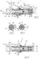
- the coupling device 1 is used to connect to a grease nipple 2 in the region of a grease nipple head 3.
- This grease nipple is in particular a conical grease nipple according to DIN 71 412, issue November 1987.
- the conical grease nipples can in different forms, shape A, shape B, shape C. be educated.
- the grease nipple has the grease nipple head 3, facing away from a threaded portion 4 of the grease nipple 2, has a truncated cone portion 5, to which, towards the threaded portion 4, an outwardly curved intermediate portion 6 connects, which represents a portion of a sphere.
- This grease nipple 2 does not have to protrude over a component which is screwed in, but instead this component can have a blind hole, in the region of which the grease nipple 2 is screwed.
- This blind hole has, for example, a diameter which is slightly larger than 15 mm.
- the coupling device 1 has a main body 7. This has an inlet opening 8 and an outlet opening 9 and a passage 10 connecting the inlet opening 8 and the outlet opening 9. Furthermore, the coupling device 1, with reference to the passage 10, externally mounted in the base body 7 pivotally mounted coupling jaws 11, specifically four identical coupling jaws 11, which are arranged around the passage 10 around.
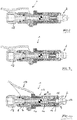
- the clutch shoes 11 protrude beyond the outlet port 9 and are in a first position as shown in FIGS Fig. 4, 6, 7 . 9, 10 and 11 is illustrated, swung in and in a second position, as in the Fig. 8 is illustrated, swung out.
- the coupling device 1 further has a sliding sleeve 12 which is displaceably mounted in the base body 7. This is against a spring force, which is applied by a helical compression spring 13, by means of a manually adjustable, pivotally mounted in the base body 7 and in the sliding sleeve 12 adjusting means 14, from a first position of the sliding sleeve 12, as shown in the Fig. 4 and 10 is illustrated, in which the sliding sleeve 12 defines the jaws 11 in its first position, in a second position of the sliding sleeve 12, illustrated in the Fig. 7 to 9 in which the sliding sleeve 12 releases the clamping jaws 11 located in the first position.
- the sliding sleeve 12 has an inner contact portion 15 which in the direction of movement according to double arrow A in Fig. 11
- the inner contact portion 15 rests in the first position of the clamping jaws 11 on parallel to the inner contact portion 15 positioned mating contact portions 17 of the jaws 11 at the sliding sleeve 12 is arranged at the displacement thereof, thus parallel to a longitudinal center axis 16 of the coupling device.
- the sliding sleeve 12 is moved away when moving in its second position from the inlet opening 8 of the base body 7.
- the inner contact portion 15 and the mating contact portions 17 are out of contact.
- the main body is essentially rotationally symmetrical with respect to its longitudinal central axis 16. Its end having the inlet opening 8 is formed with a receptacle for a rotary connection 18. This is fixed via a retaining ring 19 axially with respect to the base body 7 and sealed by a sealing ring 20 to the base body 7 out.
- the rotary connector 18 can be rotated arbitrarily with respect to the base body 7 about its longitudinal central axis 16.
- the rotary connection 18 has, in the region of its end facing away from the main body 7, a threaded connection 21 for fixed screwing to a complementary connection part of a pressure line, which is connected to a lubricating press for dispensing lubricant. Lubricant is thus conveyed by means of the lubricating press in the direction of arrow B from the rotary connection 18 through the coupling device 1 to the lubricating nipple 2.
- the base body 7 passes through in its end portion facing the rotary connection 18 a bearing axis 21, in which the actuating means 14 designed as a hand lever is mounted.
- the hand lever has two side edges 22, also a connecting web 23 on the side facing away from the bearing axis 21 of the base body 7.
- a further bearing shaft 24 is mounted, which is mounted parallel to the bearing axis 21 in the sliding sleeve 12.
- the coupling device 1 is gripped in the region of the web 23 and on the side of the main body 7 facing away from the web 23 and actuated in such a way that the web 23 is pivoted in the direction of the main body 7, this leads to the sliding sleeve 12 protruding from the inlet opening 8 in FIG Direction of the arrow B is moved and thus the inner contact portion 15 of the sliding sleeve 12 out of contact with the mating contact portions 17 of the jaws 11 passes.
- the helical compression spring 13 which is effective in the direction of the longitudinal central axis 16, stretched between the sliding sleeve 12 and a biasing sleeve 25. This constantly biased biasing sleeve 25 acts on the jaws 11 a.
- the sliding sleeve 12 is formed in two parts and consists of a front sleeve-shaped sliding part 26 and a rear, screwed into the sliding part 26 sliding part 27. Both sliding parts 26, 27 are rotationally symmetrical. The sliding part 27 is guided radially inward in an outer cylindrical shell portion 28 of the main body 7.
- the sliding part 26 has in the region of the inlet opening 8 of the base body 7 opposite end, thus in the region of the front end, a radially inwardly directed circumferential projection 29. This engages behind the clamping jaws 11 in the region of the inlet opening 8 facing away from end surfaces 53 and is applied to these in the first position of the jaws 11 at.
- the jaws 11 have in the region facing away from the inlet opening 8 a radially inwardly directed projection 30 for engaging behind the grease nipple head 3 in the region of the intermediate portion 6 in the first position of the jaws 11.
- These inwardly directed lugs 29 of the jaws 11 are arranged in the first position of the jaws 11 within the sliding sleeve 12 and thus within the sliding part 26.
- the clamping jaws 11 are pivotally mounted in the region of the inlet opening 8 of the main body 7 facing ends in an outer groove 31 of the base body 7, specifically the outer portion 31 passing through the shell portion 28 and this largely fixed in the base body 7 in the direction of movement of the sliding sleeve 12.
- the thickness of the outer groove 31 is slightly larger than the dimension of a projection 32 of the respective jaw 11 in this direction, so that the respective jaws is slightly movable in the direction of the double arrows A back and forth, whereby pivoting of the jaws 11 is possible.
- the sliding part 27 of the sliding sleeve 12 is the sliding part 27 of the sliding sleeve 12 to a movement of the sliding sleeve 12 in the direction of the inlet opening 8 limiting projection 33 of the body 7 at.
- the rotationally symmetrical preload sleeve 25 has a rear end face 34 on which the helical compression spring 13 abuts, also in the front region a circumferential radially inner recess 35 having a longitudinal portion 36 which engages longitudinally extending outer portions 38 of the jaws 11, and a transverse Section 37, which contacts 13 rear portions 39 of the jaws 11 under the action of the force of the compression coil spring.
- the depth of the outer groove 31 and the design of the outer groove 31 and projection 32 of the jaws 11 causes the respective jaws 11 in the region of the peripheral edge 40 of the base body is pivotable about this.
- the force acting on the projection 32 of the respective clamping jaw 11 via the spring-loaded pretensioning sleeve 25 is arranged at such an effective distance from the edge 40 that the respective clamping jaw 11, under the action of the pretensioning sleeve 25 in the direction of the in Fig. 11 shown first position of the jaw 11 is biased, thus the jaws are always anxious under the action of the biasing sleeve 25 moment, with their approach 30 to pivot radially inward.
- the sliding sleeve 12 can be moved freely forward and backward.
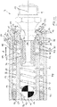
- the passage 10 through the base body 7 has a passage section 42 whose diameter is substantially smaller than a passage section 43 of the passage 10 adjoining the outlet opening 9.
- This passage section 43 also has a circular cross-section the axis is the longitudinal central axis 16.
- the passage section 42 is closable by means of a check valve. Shown is a ball 45 acted upon by a helical compression spring 44, which abuts on the main body 7 in the region of the passage section 42.
- This helical compression spring 44 is supported at the other end on a sealing sleeve 46 made of elastic material.
- the groove 48 has an extension in the longitudinal direction A, which is greater than the diameter of the respective ball 49, and is tuned such that the intermediate sleeve 47 and thus the sealing sleeve 46 by a defined amount during insertion of the lubricating nipple 2 against the force of the spring 44 are displaceable.
- the sealing sleeve 46 has an annular end face 51 which extends perpendicular to the longitudinal central axis 16 and forms the mating contact surface for the free end face of the truncated cone portion 5 of the grease nipple head 3.
- the intermediate sleeve 47 in its the truncated cone portion 5 facing region provided with a slope 52.
- the sealing sleeve 46 is biased by the helical compression spring 44 against the variable stop, which results from the interaction of the sealing sleeve 46, intermediate sleeve 47, groove 48, balls 49, hole 50 and body 7.
- Fig. 4 shows the clutch device 1 in the initial state, thus before connecting to a lubricating nipple 2.
- the sliding sleeve 12 to the rear thus in the direction of the inlet opening 8 of the actuating means 14 against the projection 33 moves.
- the jaws 11 are in their first position and it can not pivot the jaws 11 in the region of their lugs 30 radially outward, because they are prevented due to the abutment of the inner contact portion 15 of the sliding sleeve 12 to the mating contact portions 17 of the jaws 11 thereto.
- the truncated cone section 5 contacts the sealing sleeve 46 in the area of its end face 51 and displaces it against the force of the helical compression spring 44, which in turn acts on the ball 45 of the non-return valve.
- the displacement of the sealing sleeve 46 is possible due to the bearing of the sealing sleeve 46 in the intermediate sleeve 47 and the displaceability of the intermediate sleeve in the base body 7 due to the interaction of the grooves 48 and the balls 49.
- the biasing sleeve 25 in this case also has the task to fix the balls 49 in the direction radially outward.
- the forwardly moving sliding sleeve 12 first causes the exit region of the sealing sleeve 46 and the clamping jaws 11 to be covered particularly well and to provide splash protection with respect to the lubricant. Further, when uncoupling the coupling device 1, the sealing sleeve 46, which is under the bias of the helical compression spring 44, tracked and is thus in the initial stage of removing the grease nipple head 3 on this. Furthermore, because of the relatively small diameter of the passage section 42, pressure surges from the lubricating press, which are also present in the region of the rotary connection 18 due to the high pressure at the lubricating press, are minimized. As a result, the stress on the components within the base body 7, specifically ball 45, helical compression spring 44 and sealing sleeve 46 is minimized.
- the check valve with the ball 45 has the task of preventing leakage of lubricant when the coupling device is connected to a lubricant press, without being exerted on this pressure.
- the coupling device 1 can also be used with a lubricating nipple 2, which is arranged set back in a component, with an externally accessible bore section in the component, which has a diameter which is slightly larger than 15 mm.
Landscapes
- Engineering & Computer Science (AREA)
- General Engineering & Computer Science (AREA)
- Mechanical Engineering (AREA)
- Quick-Acting Or Multi-Walled Pipe Joints (AREA)
Claims (12)
- Dispositif d'accouplement (1) pour la connexion à un raccord de lubrification (2) dans la région d'une tête de raccord de lubrification (3), comprenant un corps de base (7) qui présente une ouverture d'entrée (8) et une ouverture de sortie (9) ainsi qu'un passage (10) reliant l'ouverture d'entrée (8) et l'ouverture de sortie (9), et comprenant en outre des mâchoires de serrage (11) supportées de manière pivotante dans le corps de base (7), situées à l'extérieur par rapport au passage (10), qui sont disposées autour du passage (10), les mâchoires de serrage (11) faisant saillie au-delà de l'ouverture de sortie (9) et étant refermées par pivotement dans une première position, pour venir en prise par l'arrière avec la tête de raccord de lubrification (3), et étant ouvertes par pivotement dans une deuxième position pour libérer la tête de raccord de lubrification (3), et comprenant en outre un manchon coulissant (12) supporté de manière déplaçable dans le corps de base (7), le manchon coulissant (12) pouvant être transféré à l'encontre d'une force de ressort au moyen d'un actionneur (14) supporté dans le corps de base (7) et dans le manchon coulissant (12) depuis une première position dans laquelle le manchon coulissant (12) fixe les mâchoires de serrage (11) dans leur première position, dans une deuxième position dans laquelle le manchon coulissant (12) libère les mâchoires de serrage (11) se trouvant dans la première position, caractérisé en ce que le manchon coulissant (12) présente une portion de contact intérieure (15) qui est disposée parallèlement à la direction de déplacement (A) du manchon coulissant (12) lors de son déplacement, la portion de contact intérieure (15) s'appliquant, dans la première position des mâchoires de serrage (11), contre des portions de contact conjuguées (17) des mâchoires de serrage (11) positionnées parallèlement à la portion de contact intérieure (15), et le manchon coulissant (12), lors de son déplacement dans sa deuxième position, étant déplacé depuis la position d'entrée (8) du corps de base (7) dans une position hors contact de la portion de contact intérieure (15) et des portions de contact conjuguées (17), un moyen de ressort (13) étant prévu, lequel précontraint les mâchoires de serrage (11) dans leur première position, une douille de précontrainte (25) étant disposée entre le corps de base (7) et le manchon coulissant (12), laquelle peut être déplacée dans la direction de déplacement (A) du manchon coulissant (12), la douille de précontrainte (25) agissant sur les mâchoires de serrage (11) et les précontraignant dans leur première position, le moyen de ressort (13) agissant entre le manchon coulissant (12) et la douille de précontrainte (25), les mâchoires de serrage (11) étant supportées de manière pivotante dans la région d'extrémités tournées vers l'ouverture d'entrée (8) du corps de base (7) dans une rainure extérieure (31) du corps de base (7), de manière fixée dans la direction de déplacement (A) du manchon coulissant (12), et la douille de précontrainte (25) agissant sur la mâchoire de serrage (11) respective à une distance à l'axe de pivotement (40) de ladite mâchoire de serrage générant un couple de pivotement.
- Accouplement selon la revendication 1, caractérisé en ce qu'un moyen de ressort (13) réalisé sous forme de ressort de compression à boudin agit entre le manchon coulissant (12) et la douille de précontrainte (25).
- Dispositif d'accouplement selon l'une quelconque des revendications 1 à 2, caractérisé en ce que le manchon coulissant (12) présente à l'intérieur un espace libre périphérique (41) pour recevoir les mâchoires de serrage (11) dans leur deuxième position, en particulier l'espace libre (41) étant configuré de telle sorte qu'un mouvement de pivotement des mâchoires de serrage (11) au-delà de leur deuxième position soit bloqué.
- Dispositif d'accouplement selon l'une quelconque des revendications 1 à 3, caractérisé en ce que les mâchoires de serrage (11) présentent, dans la région d'extrémités tournées vers l'ouverture d'entrée (8), une pièce (30) orientée radialement vers l'intérieur pour venir en prise par l'arrière avec la tête de raccord de lubrification (3) dans la première position des mâchoires de serrage (11) .
- Dispositif d'accouplement selon la revendication 4, caractérisé en ce que les mâchoires de serrage (11) sont disposées, dans la région de leurs extrémités opposées à l'ouverture d'entrée (8), dans la première et la deuxième position des mâchoires de serrage (11), complètement à l'intérieur du manchon coulissant (12).
- Dispositif d'accouplement selon la revendication 5, caractérisé en ce que le manchon coulissant (12) présente, dans la région de son extrémité opposée à l'ouverture d'entrée (8) du corps de base (7), une pièce (29) orientée radialement vers l'intérieur, en particulier périphérique, la pièce (29) venant en prise par l'arrière avec les mâchoires de serrage (11) dans la région de surfaces frontales (54) opposées à l'ouverture d'entrée (8) du corps de base (7), en particulier dans les premières positions du manchon coulissant (12) et des mâchoires de serrage (11), s'appliquant sur ces surfaces frontales (54).
- Dispositif d'accouplement selon l'une quelconque des revendications 1 à 6, caractérisé en ce que le corps de base (7), dans la région du passage (10), reçoit une douille d'étanchéité élastique (46) supportée de manière déplaçable dans le corps de base (7) et/ou dans une douille intermédiaire (47), laquelle douille d'étanchéité est précontrainte sous l'effet d'une force de ressort, dans la direction de l'ouverture de sortie (9) du corps de base (7), contre une butée du côté du corps de base (48, 49, 50, 7).
- Dispositif d'accouplement selon la revendication 7, caractérisé en ce que la force de ressort agissant sur la douille d'étanchéité (46) est produite par un ressort de compression à boudin (44) qui agit entre la douille d'étanchéité (46) et le corps de base (7), en particulier le ressort de compression à boudin (44) s'appuie contre la douille d'étanchéité (46) et contre une bille (45), la bille (45), dans la position de fermeture, fermant une portion (42) du passage (10) tournée vers l'ouverture d'entrée (8) du corps de base (7).
- Dispositif d'accouplement selon l'une quelconque des revendications 1 à 8, caractérisé en ce qu'une portion amont (42) du passage (10) présente un diamètre plus petit qu'une portion aval (43) du passage (10).
- Dispositif d'accouplement selon l'une quelconque des revendications 7 à 9, caractérisé en ce que la douille intermédiaire (47), en particulier une douille intermédiaire métallique (47), est disposée entre la douille d'étanchéité (46) et le corps de base (7), la douille intermédiaire (47) présentant des guides (48) pour des éléments de roulement (49), en particulier pour des billes (49), s'étendant à l'extérieur dans sa direction longitudinale, qui sont fixés dans la direction de coulissement (A) de la douille intermédiaire (47) et radialement vers l'extérieur, en particulier qui sont fixés radialement vers l'extérieur au moyen de la douille de précontrainte (25).
- Dispositif d'accouplement selon l'une quelconque des revendications 1 à 10, caractérisé en ce que l'actionneur (14) est un actionneur réglable manuellement (14), en particulier un levier pivotant, qui est supporté de manière pivotante dans le corps de base (7), et, à distance de l'axe de pivotement (21) dans le corps de base (7), est supporté de manière pivotante dans le manchon coulissant (12).
- Dispositif d'accouplement selon l'une quelconque des revendications 1 à 11, caractérisé en ce que le manchon coulissant (12), partant de son extrémité opposée à l'ouverture d'entrée (8) du corps de base (7), jusqu'à une longueur de plus de 20 mm, en particulier jusqu'à 60 mm, présente un diamètre extérieur constant de 15 mm maximum.
Priority Applications (3)
| Application Number | Priority Date | Filing Date | Title |
|---|---|---|---|
| ES16188311T ES2700429T3 (es) | 2016-09-12 | 2016-09-12 | Dispositivo de acoplamiento para la unión a un racor de engrase |
| EP16188311.1A EP3293436B1 (fr) | 2016-09-12 | 2016-09-12 | Dispositif de couplage a relier a un mamelon de graissage |
| PCT/EP2017/071947 WO2018046396A1 (fr) | 2016-09-12 | 2017-09-01 | Dispositif de raccordement servant à la liaison à un raccord fileté de graissage |
Applications Claiming Priority (1)
| Application Number | Priority Date | Filing Date | Title |
|---|---|---|---|
| EP16188311.1A EP3293436B1 (fr) | 2016-09-12 | 2016-09-12 | Dispositif de couplage a relier a un mamelon de graissage |
Publications (2)
| Publication Number | Publication Date |
|---|---|
| EP3293436A1 EP3293436A1 (fr) | 2018-03-14 |
| EP3293436B1 true EP3293436B1 (fr) | 2018-08-29 |
Family
ID=56920572
Family Applications (1)
| Application Number | Title | Priority Date | Filing Date |
|---|---|---|---|
| EP16188311.1A Active EP3293436B1 (fr) | 2016-09-12 | 2016-09-12 | Dispositif de couplage a relier a un mamelon de graissage |
Country Status (3)
| Country | Link |
|---|---|
| EP (1) | EP3293436B1 (fr) |
| ES (1) | ES2700429T3 (fr) |
| WO (1) | WO2018046396A1 (fr) |
Cited By (2)
| Publication number | Priority date | Publication date | Assignee | Title |
|---|---|---|---|---|
| EP4491916A1 (fr) * | 2023-07-12 | 2025-01-15 | Sartorius Stedim Biotech GmbH | Dispositif d'accouplement destiné à être couplé à un dispositif à diaphragme, dispositif à diaphragme et procédé |
| DE102024130256A1 (de) | 2024-10-17 | 2026-04-23 | Rudolf Schlenker | Kupplung zur Ankoppelung an einen Nippel |
Families Citing this family (6)
| Publication number | Priority date | Publication date | Assignee | Title |
|---|---|---|---|---|
| TWM545862U (zh) * | 2017-04-12 | 2017-07-21 | King Cho Machinery Industrial Co Ltd | 黃油槍的接嘴結構 |
| EP3781858A4 (fr) * | 2018-04-18 | 2021-12-22 | Univer-Co (2013) Inc. | Coupleur de pistolet graisseur |
| CN109114407B (zh) * | 2018-10-12 | 2024-08-30 | 山西汾西矿业(集团)有限责任公司 | 黄油枪内涨式注油嘴 |
| CN111594742A (zh) * | 2020-05-28 | 2020-08-28 | 诸暨荣德机械有限公司 | 固定式爪片油脂枪连接器 |
| CN113915511A (zh) * | 2021-11-04 | 2022-01-11 | 中冶长天国际工程有限责任公司 | 一种加注枪的安装座、加注机构及加注设备 |
| CN115218109B (zh) * | 2022-08-02 | 2024-05-21 | 永康市富宇汽保工具有限公司 | 一种电动黄油枪接头 |
Family Cites Families (4)
| Publication number | Priority date | Publication date | Assignee | Title |
|---|---|---|---|---|
| US2070013A (en) * | 1935-04-29 | 1937-02-09 | Min A Max Co Inc | Lubricating apparatus |
| DE2805829A1 (de) | 1978-02-11 | 1979-08-16 | Mato Masch & Metallwaren | Greifmundstueck fuer hydraulik- schmiernippel |
| DE29509667U1 (de) | 1995-06-21 | 1995-08-24 | Reiner Chemische Fabrik GmbH, 67685 Weilerbach | Verbindungsschlauch für Schmierpressen o.dgl. |
| EP2531766B1 (fr) * | 2009-12-01 | 2016-11-09 | Gurtech (PTY) Ltd | Coupleur de graisse amélioré |
-
2016
- 2016-09-12 EP EP16188311.1A patent/EP3293436B1/fr active Active
- 2016-09-12 ES ES16188311T patent/ES2700429T3/es active Active
-
2017
- 2017-09-01 WO PCT/EP2017/071947 patent/WO2018046396A1/fr not_active Ceased
Cited By (3)
| Publication number | Priority date | Publication date | Assignee | Title |
|---|---|---|---|---|
| EP4491916A1 (fr) * | 2023-07-12 | 2025-01-15 | Sartorius Stedim Biotech GmbH | Dispositif d'accouplement destiné à être couplé à un dispositif à diaphragme, dispositif à diaphragme et procédé |
| WO2025012220A1 (fr) * | 2023-07-12 | 2025-01-16 | Sartorius Stedim Biotech Gmbh | Dispositif d'accouplement destiné à être accouplé à un dispositif à membrane, dispositif à membrane et procédé |
| DE102024130256A1 (de) | 2024-10-17 | 2026-04-23 | Rudolf Schlenker | Kupplung zur Ankoppelung an einen Nippel |
Also Published As
| Publication number | Publication date |
|---|---|
| EP3293436A1 (fr) | 2018-03-14 |
| ES2700429T3 (es) | 2019-02-15 |
| WO2018046396A1 (fr) | 2018-03-15 |
Similar Documents
| Publication | Publication Date | Title |
|---|---|---|
| EP3293436B1 (fr) | Dispositif de couplage a relier a un mamelon de graissage | |
| DE112008000328B4 (de) | Schnellverbindungsverbinder mit Toleranzanpassung | |
| DE2923902C2 (fr) | ||
| DE60220623T2 (de) | Rohrverbindungen | |
| DE60305236T2 (de) | Verbindungsvorrichtung zur Verbindung von zwei Rohren | |
| DE102014010570B4 (de) | Kupplungsteil für eine Kupplung für Druckmittelleitungen | |
| EP3485192B1 (fr) | Accouplement à verrouillage | |
| WO2008145435A1 (fr) | Connecteur électrique doté d'un élément d'étanchéité | |
| DE202008002265U1 (de) | Vorrichtung zum Aufweiten von Rohren | |
| DE60017999T2 (de) | Verbindungsmittel für Anschliessen eines Rohres an röhrenförmigen Körper | |
| EP2843279B1 (fr) | Organe d'arrêt | |
| DE102015222640A1 (de) | Kupplungselement für eine Kupplung zur Verbindung von Druckmittelleitungen | |
| WO2009007165A1 (fr) | Tuyau d'air de charge | |
| EP0754899B1 (fr) | Soupape sphérique avec raccord rapide | |
| DE2820168C2 (de) | Dichtung für eine Ventilspindel | |
| DE102013102384B4 (de) | Koaxiale Hochdruckkupplung mit beim Kupplungsvorgang wirksamer Abdichtung von Steckerteil und Aufnahmeteil | |
| EP2505895A1 (fr) | Elément de raccordement d'un raccord de conduit à moyen de pression | |
| EP4390207B1 (fr) | Pièce d'accouplement pour un accouplement hydraulique | |
| EP3475601B1 (fr) | Système de raccordement permettant de réaliser un raccord tournant pour un élément de raccordement | |
| EP2103859A1 (fr) | Embrayage constitué d'éléments d'embrayage | |
| DE19809852C2 (de) | Anschlußvorrichtung für Sanitär-Rohrleitungen | |
| EP1095225A1 (fr) | Emboitement auto-etanche avec garniture pour verrouillage | |
| DE102018128252A1 (de) | Spannbolzen zum lösbaren Verbinden von Bauteilen | |
| EP3839318B1 (fr) | Élément à vis et système | |
| DE102011078480A1 (de) | Geber für ein hydraulisches Betätigungselement |
Legal Events
| Date | Code | Title | Description |
|---|---|---|---|
| PUAI | Public reference made under article 153(3) epc to a published international application that has entered the european phase |
Free format text: ORIGINAL CODE: 0009012 |
|
| 17P | Request for examination filed |
Effective date: 20170913 |
|
| AK | Designated contracting states |
Kind code of ref document: A1 Designated state(s): AL AT BE BG CH CY CZ DE DK EE ES FI FR GB GR HR HU IE IS IT LI LT LU LV MC MK MT NL NO PL PT RO RS SE SI SK SM TR |
|
| AX | Request for extension of the european patent |
Extension state: BA ME |
|
| GRAP | Despatch of communication of intention to grant a patent |
Free format text: ORIGINAL CODE: EPIDOSNIGR1 |
|
| INTG | Intention to grant announced |
Effective date: 20180403 |
|
| GRAS | Grant fee paid |
Free format text: ORIGINAL CODE: EPIDOSNIGR3 |
|
| GRAA | (expected) grant |
Free format text: ORIGINAL CODE: 0009210 |
|
| AK | Designated contracting states |
Kind code of ref document: B1 Designated state(s): AL AT BE BG CH CY CZ DE DK EE ES FI FR GB GR HR HU IE IS IT LI LT LU LV MC MK MT NL NO PL PT RO RS SE SI SK SM TR |
|
| REG | Reference to a national code |
Ref country code: GB Ref legal event code: FG4D Free format text: NOT ENGLISH |
|
| REG | Reference to a national code |
Ref country code: CH Ref legal event code: EP |
|
| REG | Reference to a national code |
Ref country code: AT Ref legal event code: REF Ref document number: 1035531 Country of ref document: AT Kind code of ref document: T Effective date: 20180915 |
|
| REG | Reference to a national code |
Ref country code: IE Ref legal event code: FG4D Free format text: LANGUAGE OF EP DOCUMENT: GERMAN |
|
| REG | Reference to a national code |
Ref country code: DE Ref legal event code: R096 Ref document number: 502016001803 Country of ref document: DE |
|
| REG | Reference to a national code |
Ref country code: FR Ref legal event code: PLFP Year of fee payment: 3 |
|
| REG | Reference to a national code |
Ref country code: NL Ref legal event code: FP |
|
| REG | Reference to a national code |
Ref country code: LT Ref legal event code: MG4D |
|
| PG25 | Lapsed in a contracting state [announced via postgrant information from national office to epo] |
Ref country code: GR Free format text: LAPSE BECAUSE OF FAILURE TO SUBMIT A TRANSLATION OF THE DESCRIPTION OR TO PAY THE FEE WITHIN THE PRESCRIBED TIME-LIMIT Effective date: 20181130 Ref country code: RS Free format text: LAPSE BECAUSE OF FAILURE TO SUBMIT A TRANSLATION OF THE DESCRIPTION OR TO PAY THE FEE WITHIN THE PRESCRIBED TIME-LIMIT Effective date: 20180829 Ref country code: LT Free format text: LAPSE BECAUSE OF FAILURE TO SUBMIT A TRANSLATION OF THE DESCRIPTION OR TO PAY THE FEE WITHIN THE PRESCRIBED TIME-LIMIT Effective date: 20180829 Ref country code: SE Free format text: LAPSE BECAUSE OF FAILURE TO SUBMIT A TRANSLATION OF THE DESCRIPTION OR TO PAY THE FEE WITHIN THE PRESCRIBED TIME-LIMIT Effective date: 20180829 Ref country code: BG Free format text: LAPSE BECAUSE OF FAILURE TO SUBMIT A TRANSLATION OF THE DESCRIPTION OR TO PAY THE FEE WITHIN THE PRESCRIBED TIME-LIMIT Effective date: 20181129 Ref country code: FI Free format text: LAPSE BECAUSE OF FAILURE TO SUBMIT A TRANSLATION OF THE DESCRIPTION OR TO PAY THE FEE WITHIN THE PRESCRIBED TIME-LIMIT Effective date: 20180829 Ref country code: NO Free format text: LAPSE BECAUSE OF FAILURE TO SUBMIT A TRANSLATION OF THE DESCRIPTION OR TO PAY THE FEE WITHIN THE PRESCRIBED TIME-LIMIT Effective date: 20181129 Ref country code: IS Free format text: LAPSE BECAUSE OF FAILURE TO SUBMIT A TRANSLATION OF THE DESCRIPTION OR TO PAY THE FEE WITHIN THE PRESCRIBED TIME-LIMIT Effective date: 20181229 |
|
| REG | Reference to a national code |
Ref country code: CH Ref legal event code: NV Representative=s name: BOVARD AG PATENT- UND MARKENANWAELTE, CH |
|
| REG | Reference to a national code |
Ref country code: ES Ref legal event code: FG2A Ref document number: 2700429 Country of ref document: ES Kind code of ref document: T3 Effective date: 20190215 |
|
| PG25 | Lapsed in a contracting state [announced via postgrant information from national office to epo] |
Ref country code: LV Free format text: LAPSE BECAUSE OF FAILURE TO SUBMIT A TRANSLATION OF THE DESCRIPTION OR TO PAY THE FEE WITHIN THE PRESCRIBED TIME-LIMIT Effective date: 20180829 Ref country code: HR Free format text: LAPSE BECAUSE OF FAILURE TO SUBMIT A TRANSLATION OF THE DESCRIPTION OR TO PAY THE FEE WITHIN THE PRESCRIBED TIME-LIMIT Effective date: 20180829 Ref country code: AL Free format text: LAPSE BECAUSE OF FAILURE TO SUBMIT A TRANSLATION OF THE DESCRIPTION OR TO PAY THE FEE WITHIN THE PRESCRIBED TIME-LIMIT Effective date: 20180829 |
|
| PG25 | Lapsed in a contracting state [announced via postgrant information from national office to epo] |
Ref country code: EE Free format text: LAPSE BECAUSE OF FAILURE TO SUBMIT A TRANSLATION OF THE DESCRIPTION OR TO PAY THE FEE WITHIN THE PRESCRIBED TIME-LIMIT Effective date: 20180829 Ref country code: IT Free format text: LAPSE BECAUSE OF FAILURE TO SUBMIT A TRANSLATION OF THE DESCRIPTION OR TO PAY THE FEE WITHIN THE PRESCRIBED TIME-LIMIT Effective date: 20180829 Ref country code: RO Free format text: LAPSE BECAUSE OF FAILURE TO SUBMIT A TRANSLATION OF THE DESCRIPTION OR TO PAY THE FEE WITHIN THE PRESCRIBED TIME-LIMIT Effective date: 20180829 Ref country code: CZ Free format text: LAPSE BECAUSE OF FAILURE TO SUBMIT A TRANSLATION OF THE DESCRIPTION OR TO PAY THE FEE WITHIN THE PRESCRIBED TIME-LIMIT Effective date: 20180829 Ref country code: PL Free format text: LAPSE BECAUSE OF FAILURE TO SUBMIT A TRANSLATION OF THE DESCRIPTION OR TO PAY THE FEE WITHIN THE PRESCRIBED TIME-LIMIT Effective date: 20180829 |
|
| PG25 | Lapsed in a contracting state [announced via postgrant information from national office to epo] |
Ref country code: DK Free format text: LAPSE BECAUSE OF FAILURE TO SUBMIT A TRANSLATION OF THE DESCRIPTION OR TO PAY THE FEE WITHIN THE PRESCRIBED TIME-LIMIT Effective date: 20180829 Ref country code: SK Free format text: LAPSE BECAUSE OF FAILURE TO SUBMIT A TRANSLATION OF THE DESCRIPTION OR TO PAY THE FEE WITHIN THE PRESCRIBED TIME-LIMIT Effective date: 20180829 Ref country code: SM Free format text: LAPSE BECAUSE OF FAILURE TO SUBMIT A TRANSLATION OF THE DESCRIPTION OR TO PAY THE FEE WITHIN THE PRESCRIBED TIME-LIMIT Effective date: 20180829 |
|
| REG | Reference to a national code |
Ref country code: DE Ref legal event code: R097 Ref document number: 502016001803 Country of ref document: DE |
|
| REG | Reference to a national code |
Ref country code: BE Ref legal event code: MM Effective date: 20180930 |
|
| REG | Reference to a national code |
Ref country code: IE Ref legal event code: MM4A |
|
| PG25 | Lapsed in a contracting state [announced via postgrant information from national office to epo] |
Ref country code: LU Free format text: LAPSE BECAUSE OF NON-PAYMENT OF DUE FEES Effective date: 20180912 Ref country code: MC Free format text: LAPSE BECAUSE OF FAILURE TO SUBMIT A TRANSLATION OF THE DESCRIPTION OR TO PAY THE FEE WITHIN THE PRESCRIBED TIME-LIMIT Effective date: 20180829 |
|
| PLBE | No opposition filed within time limit |
Free format text: ORIGINAL CODE: 0009261 |
|
| STAA | Information on the status of an ep patent application or granted ep patent |
Free format text: STATUS: NO OPPOSITION FILED WITHIN TIME LIMIT |
|
| PG25 | Lapsed in a contracting state [announced via postgrant information from national office to epo] |
Ref country code: IE Free format text: LAPSE BECAUSE OF NON-PAYMENT OF DUE FEES Effective date: 20180912 |
|
| 26N | No opposition filed |
Effective date: 20190531 |
|
| PG25 | Lapsed in a contracting state [announced via postgrant information from national office to epo] |
Ref country code: SI Free format text: LAPSE BECAUSE OF FAILURE TO SUBMIT A TRANSLATION OF THE DESCRIPTION OR TO PAY THE FEE WITHIN THE PRESCRIBED TIME-LIMIT Effective date: 20180829 Ref country code: BE Free format text: LAPSE BECAUSE OF NON-PAYMENT OF DUE FEES Effective date: 20180930 |
|
| PG25 | Lapsed in a contracting state [announced via postgrant information from national office to epo] |
Ref country code: MT Free format text: LAPSE BECAUSE OF FAILURE TO SUBMIT A TRANSLATION OF THE DESCRIPTION OR TO PAY THE FEE WITHIN THE PRESCRIBED TIME-LIMIT Effective date: 20180829 |
|
| PG25 | Lapsed in a contracting state [announced via postgrant information from national office to epo] |
Ref country code: TR Free format text: LAPSE BECAUSE OF FAILURE TO SUBMIT A TRANSLATION OF THE DESCRIPTION OR TO PAY THE FEE WITHIN THE PRESCRIBED TIME-LIMIT Effective date: 20180829 |
|
| PG25 | Lapsed in a contracting state [announced via postgrant information from national office to epo] |
Ref country code: PT Free format text: LAPSE BECAUSE OF FAILURE TO SUBMIT A TRANSLATION OF THE DESCRIPTION OR TO PAY THE FEE WITHIN THE PRESCRIBED TIME-LIMIT Effective date: 20180829 |
|
| PG25 | Lapsed in a contracting state [announced via postgrant information from national office to epo] |
Ref country code: HU Free format text: LAPSE BECAUSE OF FAILURE TO SUBMIT A TRANSLATION OF THE DESCRIPTION OR TO PAY THE FEE WITHIN THE PRESCRIBED TIME-LIMIT; INVALID AB INITIO Effective date: 20160912 Ref country code: MK Free format text: LAPSE BECAUSE OF NON-PAYMENT OF DUE FEES Effective date: 20180829 Ref country code: CY Free format text: LAPSE BECAUSE OF FAILURE TO SUBMIT A TRANSLATION OF THE DESCRIPTION OR TO PAY THE FEE WITHIN THE PRESCRIBED TIME-LIMIT Effective date: 20180829 |
|
| REG | Reference to a national code |
Ref country code: CH Ref legal event code: U11 Free format text: ST27 STATUS EVENT CODE: U-0-0-U10-U11 (AS PROVIDED BY THE NATIONAL OFFICE) Effective date: 20251001 |
|
| PGFP | Annual fee paid to national office [announced via postgrant information from national office to epo] |
Ref country code: NL Payment date: 20250918 Year of fee payment: 10 |
|
| PGFP | Annual fee paid to national office [announced via postgrant information from national office to epo] |
Ref country code: GB Payment date: 20250919 Year of fee payment: 10 |
|
| PGFP | Annual fee paid to national office [announced via postgrant information from national office to epo] |
Ref country code: FR Payment date: 20250922 Year of fee payment: 10 Ref country code: AT Payment date: 20250919 Year of fee payment: 10 |
|
| PGFP | Annual fee paid to national office [announced via postgrant information from national office to epo] |
Ref country code: DE Payment date: 20251027 Year of fee payment: 10 |
|
| PGFP | Annual fee paid to national office [announced via postgrant information from national office to epo] |
Ref country code: CH Payment date: 20251001 Year of fee payment: 10 |
|
| PGFP | Annual fee paid to national office [announced via postgrant information from national office to epo] |
Ref country code: ES Payment date: 20251028 Year of fee payment: 10 |