EP3293452A1 - Leuchtenverbindungsanordnung - Google Patents
Leuchtenverbindungsanordnung Download PDFInfo
- Publication number
- EP3293452A1 EP3293452A1 EP17189653.3A EP17189653A EP3293452A1 EP 3293452 A1 EP3293452 A1 EP 3293452A1 EP 17189653 A EP17189653 A EP 17189653A EP 3293452 A1 EP3293452 A1 EP 3293452A1
- Authority
- EP
- European Patent Office
- Prior art keywords
- pcb
- lead
- hole
- base plate
- lighting fixture
- Prior art date
- Legal status (The legal status is an assumption and is not a legal conclusion. Google has not performed a legal analysis and makes no representation as to the accuracy of the status listed.)
- Withdrawn
Links
- 238000004891 communication Methods 0.000 claims abstract description 8
- 238000000034 method Methods 0.000 claims description 10
- CEOCDNVZRAIOQZ-UHFFFAOYSA-N pentachlorobenzene Chemical compound ClC1=CC(Cl)=C(Cl)C(Cl)=C1Cl CEOCDNVZRAIOQZ-UHFFFAOYSA-N 0.000 claims 11
- SXHLTVKPNQVZGL-UHFFFAOYSA-N 1,2-dichloro-3-(3-chlorophenyl)benzene Chemical compound ClC1=CC=CC(C=2C(=C(Cl)C=CC=2)Cl)=C1 SXHLTVKPNQVZGL-UHFFFAOYSA-N 0.000 description 33
- 230000000712 assembly Effects 0.000 description 7
- 238000000429 assembly Methods 0.000 description 7
- NIXOWILDQLNWCW-UHFFFAOYSA-N acrylic acid group Chemical group C(C=C)(=O)O NIXOWILDQLNWCW-UHFFFAOYSA-N 0.000 description 1
- XAGFODPZIPBFFR-UHFFFAOYSA-N aluminium Chemical compound [Al] XAGFODPZIPBFFR-UHFFFAOYSA-N 0.000 description 1
- 229910052782 aluminium Inorganic materials 0.000 description 1
- -1 but not limited to Substances 0.000 description 1
- 239000003086 colorant Substances 0.000 description 1
- 150000001875 compounds Chemical class 0.000 description 1
- 239000004020 conductor Substances 0.000 description 1
- 239000000356 contaminant Substances 0.000 description 1
- 238000005516 engineering process Methods 0.000 description 1
- 230000007613 environmental effect Effects 0.000 description 1
- 239000007789 gas Substances 0.000 description 1
- 238000005286 illumination Methods 0.000 description 1
- 239000011261 inert gas Substances 0.000 description 1
- 238000009434 installation Methods 0.000 description 1
- 239000012212 insulator Substances 0.000 description 1
- 238000004519 manufacturing process Methods 0.000 description 1
- 239000000463 material Substances 0.000 description 1
- 238000012986 modification Methods 0.000 description 1
- 230000004048 modification Effects 0.000 description 1
- 238000007789 sealing Methods 0.000 description 1
- 238000005476 soldering Methods 0.000 description 1
Images

Classifications
-
- F—MECHANICAL ENGINEERING; LIGHTING; HEATING; WEAPONS; BLASTING
- F21—LIGHTING
- F21V—FUNCTIONAL FEATURES OR DETAILS OF LIGHTING DEVICES OR SYSTEMS THEREOF; STRUCTURAL COMBINATIONS OF LIGHTING DEVICES WITH OTHER ARTICLES, NOT OTHERWISE PROVIDED FOR
- F21V23/00—Arrangement of electric circuit elements in or on lighting devices
- F21V23/06—Arrangement of electric circuit elements in or on lighting devices the elements being coupling devices, e.g. connectors
-
- F—MECHANICAL ENGINEERING; LIGHTING; HEATING; WEAPONS; BLASTING
- F21—LIGHTING
- F21S—NON-PORTABLE LIGHTING DEVICES; SYSTEMS THEREOF; VEHICLE LIGHTING DEVICES SPECIALLY ADAPTED FOR VEHICLE EXTERIORS
- F21S8/00—Lighting devices intended for fixed installation
- F21S8/04—Lighting devices intended for fixed installation intended only for mounting on a ceiling or the like overhead structures
-
- F—MECHANICAL ENGINEERING; LIGHTING; HEATING; WEAPONS; BLASTING
- F21—LIGHTING
- F21S—NON-PORTABLE LIGHTING DEVICES; SYSTEMS THEREOF; VEHICLE LIGHTING DEVICES SPECIALLY ADAPTED FOR VEHICLE EXTERIORS
- F21S8/00—Lighting devices intended for fixed installation
- F21S8/04—Lighting devices intended for fixed installation intended only for mounting on a ceiling or the like overhead structures
- F21S8/06—Lighting devices intended for fixed installation intended only for mounting on a ceiling or the like overhead structures by suspension
-
- F—MECHANICAL ENGINEERING; LIGHTING; HEATING; WEAPONS; BLASTING
- F21—LIGHTING
- F21V—FUNCTIONAL FEATURES OR DETAILS OF LIGHTING DEVICES OR SYSTEMS THEREOF; STRUCTURAL COMBINATIONS OF LIGHTING DEVICES WITH OTHER ARTICLES, NOT OTHERWISE PROVIDED FOR
- F21V21/00—Supporting, suspending, or attaching arrangements for lighting devices; Hand grips
- F21V21/008—Suspending from a cable or suspension line
-
- F—MECHANICAL ENGINEERING; LIGHTING; HEATING; WEAPONS; BLASTING
- F21—LIGHTING
- F21V—FUNCTIONAL FEATURES OR DETAILS OF LIGHTING DEVICES OR SYSTEMS THEREOF; STRUCTURAL COMBINATIONS OF LIGHTING DEVICES WITH OTHER ARTICLES, NOT OTHERWISE PROVIDED FOR
- F21V23/00—Arrangement of electric circuit elements in or on lighting devices
- F21V23/003—Arrangement of electric circuit elements in or on lighting devices the elements being electronics drivers or controllers for operating the light source, e.g. for a LED array
-
- F—MECHANICAL ENGINEERING; LIGHTING; HEATING; WEAPONS; BLASTING
- F21—LIGHTING
- F21V—FUNCTIONAL FEATURES OR DETAILS OF LIGHTING DEVICES OR SYSTEMS THEREOF; STRUCTURAL COMBINATIONS OF LIGHTING DEVICES WITH OTHER ARTICLES, NOT OTHERWISE PROVIDED FOR
- F21V27/00—Cable-stowing arrangements structurally associated with lighting devices, e.g. reels
- F21V27/02—Cable inlets
-
- F—MECHANICAL ENGINEERING; LIGHTING; HEATING; WEAPONS; BLASTING
- F21—LIGHTING
- F21V—FUNCTIONAL FEATURES OR DETAILS OF LIGHTING DEVICES OR SYSTEMS THEREOF; STRUCTURAL COMBINATIONS OF LIGHTING DEVICES WITH OTHER ARTICLES, NOT OTHERWISE PROVIDED FOR
- F21V29/00—Protecting lighting devices from thermal damage; Cooling or heating arrangements specially adapted for lighting devices or systems
- F21V29/50—Cooling arrangements
- F21V29/70—Cooling arrangements characterised by passive heat-dissipating elements, e.g. heat-sinks
-
- F—MECHANICAL ENGINEERING; LIGHTING; HEATING; WEAPONS; BLASTING
- F21—LIGHTING
- F21V—FUNCTIONAL FEATURES OR DETAILS OF LIGHTING DEVICES OR SYSTEMS THEREOF; STRUCTURAL COMBINATIONS OF LIGHTING DEVICES WITH OTHER ARTICLES, NOT OTHERWISE PROVIDED FOR
- F21V29/00—Protecting lighting devices from thermal damage; Cooling or heating arrangements specially adapted for lighting devices or systems
- F21V29/50—Cooling arrangements
- F21V29/70—Cooling arrangements characterised by passive heat-dissipating elements, e.g. heat-sinks
- F21V29/74—Cooling arrangements characterised by passive heat-dissipating elements, e.g. heat-sinks with fins or blades
- F21V29/77—Cooling arrangements characterised by passive heat-dissipating elements, e.g. heat-sinks with fins or blades with essentially identical diverging planar fins or blades, e.g. with fan-like or star-like cross-section
- F21V29/773—Cooling arrangements characterised by passive heat-dissipating elements, e.g. heat-sinks with fins or blades with essentially identical diverging planar fins or blades, e.g. with fan-like or star-like cross-section the planes containing the fins or blades having the direction of the light emitting axis
-
- F—MECHANICAL ENGINEERING; LIGHTING; HEATING; WEAPONS; BLASTING
- F21—LIGHTING
- F21V—FUNCTIONAL FEATURES OR DETAILS OF LIGHTING DEVICES OR SYSTEMS THEREOF; STRUCTURAL COMBINATIONS OF LIGHTING DEVICES WITH OTHER ARTICLES, NOT OTHERWISE PROVIDED FOR
- F21V31/00—Gas-tight or water-tight arrangements
- F21V31/005—Sealing arrangements therefor
-
- F—MECHANICAL ENGINEERING; LIGHTING; HEATING; WEAPONS; BLASTING
- F21—LIGHTING
- F21V—FUNCTIONAL FEATURES OR DETAILS OF LIGHTING DEVICES OR SYSTEMS THEREOF; STRUCTURAL COMBINATIONS OF LIGHTING DEVICES WITH OTHER ARTICLES, NOT OTHERWISE PROVIDED FOR
- F21V29/00—Protecting lighting devices from thermal damage; Cooling or heating arrangements specially adapted for lighting devices or systems
- F21V29/50—Cooling arrangements
- F21V29/502—Cooling arrangements characterised by the adaptation for cooling of specific components
- F21V29/503—Cooling arrangements characterised by the adaptation for cooling of specific components of light sources
-
- F—MECHANICAL ENGINEERING; LIGHTING; HEATING; WEAPONS; BLASTING
- F21—LIGHTING
- F21V—FUNCTIONAL FEATURES OR DETAILS OF LIGHTING DEVICES OR SYSTEMS THEREOF; STRUCTURAL COMBINATIONS OF LIGHTING DEVICES WITH OTHER ARTICLES, NOT OTHERWISE PROVIDED FOR
- F21V29/00—Protecting lighting devices from thermal damage; Cooling or heating arrangements specially adapted for lighting devices or systems
- F21V29/50—Cooling arrangements
- F21V29/502—Cooling arrangements characterised by the adaptation for cooling of specific components
- F21V29/508—Cooling arrangements characterised by the adaptation for cooling of specific components of electrical circuits
-
- F—MECHANICAL ENGINEERING; LIGHTING; HEATING; WEAPONS; BLASTING
- F21—LIGHTING
- F21V—FUNCTIONAL FEATURES OR DETAILS OF LIGHTING DEVICES OR SYSTEMS THEREOF; STRUCTURAL COMBINATIONS OF LIGHTING DEVICES WITH OTHER ARTICLES, NOT OTHERWISE PROVIDED FOR
- F21V5/00—Refractors for light sources
- F21V5/04—Refractors for light sources of lens shape
- F21V5/048—Refractors for light sources of lens shape the lens being a simple lens adapted to cooperate with a point-like source for emitting mainly in one direction and having an axis coincident with the main light transmission direction, e.g. convergent or divergent lenses, plano-concave or plano-convex lenses
-
- F—MECHANICAL ENGINEERING; LIGHTING; HEATING; WEAPONS; BLASTING
- F21—LIGHTING
- F21V—FUNCTIONAL FEATURES OR DETAILS OF LIGHTING DEVICES OR SYSTEMS THEREOF; STRUCTURAL COMBINATIONS OF LIGHTING DEVICES WITH OTHER ARTICLES, NOT OTHERWISE PROVIDED FOR
- F21V7/00—Reflectors for light sources
-
- F—MECHANICAL ENGINEERING; LIGHTING; HEATING; WEAPONS; BLASTING
- F21—LIGHTING
- F21W—INDEXING SCHEME ASSOCIATED WITH SUBCLASSES F21K, F21L, F21S and F21V, RELATING TO USES OR APPLICATIONS OF LIGHTING DEVICES OR SYSTEMS
- F21W2131/00—Use or application of lighting devices or systems not provided for in codes F21W2102/00-F21W2121/00
- F21W2131/40—Lighting for industrial, commercial, recreational or military use
-
- F—MECHANICAL ENGINEERING; LIGHTING; HEATING; WEAPONS; BLASTING
- F21—LIGHTING
- F21W—INDEXING SCHEME ASSOCIATED WITH SUBCLASSES F21K, F21L, F21S and F21V, RELATING TO USES OR APPLICATIONS OF LIGHTING DEVICES OR SYSTEMS
- F21W2131/00—Use or application of lighting devices or systems not provided for in codes F21W2102/00-F21W2121/00
- F21W2131/40—Lighting for industrial, commercial, recreational or military use
- F21W2131/406—Lighting for industrial, commercial, recreational or military use for theatres, stages or film studios
-
- F—MECHANICAL ENGINEERING; LIGHTING; HEATING; WEAPONS; BLASTING
- F21—LIGHTING
- F21W—INDEXING SCHEME ASSOCIATED WITH SUBCLASSES F21K, F21L, F21S and F21V, RELATING TO USES OR APPLICATIONS OF LIGHTING DEVICES OR SYSTEMS
- F21W2131/00—Use or application of lighting devices or systems not provided for in codes F21W2102/00-F21W2121/00
- F21W2131/40—Lighting for industrial, commercial, recreational or military use
- F21W2131/407—Lighting for industrial, commercial, recreational or military use for indoor arenas
-
- F—MECHANICAL ENGINEERING; LIGHTING; HEATING; WEAPONS; BLASTING
- F21—LIGHTING
- F21Y—INDEXING SCHEME ASSOCIATED WITH SUBCLASSES F21K, F21L, F21S and F21V, RELATING TO THE FORM OR THE KIND OF THE LIGHT SOURCES OR OF THE COLOUR OF THE LIGHT EMITTED
- F21Y2105/00—Planar light sources
-
- F—MECHANICAL ENGINEERING; LIGHTING; HEATING; WEAPONS; BLASTING
- F21—LIGHTING
- F21Y—INDEXING SCHEME ASSOCIATED WITH SUBCLASSES F21K, F21L, F21S and F21V, RELATING TO THE FORM OR THE KIND OF THE LIGHT SOURCES OR OF THE COLOUR OF THE LIGHT EMITTED
- F21Y2115/00—Light-generating elements of semiconductor light sources
- F21Y2115/10—Light-emitting diodes [LED]
Definitions
- the present disclosure relates to lighting fixtures and, more specifically, to connector assemblies for connecting driver units to driven units.
- Lighting fixtures for high bay facilities are designed for use in buildings with high ceilings or "high bays" such as warehouses, manufacturing facilities, retail stores, or the like where the ceilings can be between 20 and 60 feet high.
- High bay facilities typically mount lighting fixtures at or near the ceiling. At such heights, lighting fixtures used in high bay facilities require increased illumination output compared to lighting solutions used in standard offices or homes that have ceilings between 8 and 14 feet high.
- LED lighting fixtures require an LED driver to be connected to one or more LEDs which produces the light.
- the one or more LEDs can be assembled and arranged on a printed circuit board (PCB).
- the LED driver is typically remote from the PCB and is connected to the PCB by one or more lead wires.
- a lighting fixture in an aspect of the present disclosure, includes a driver, a heat sink assembly, a light generating assembly, a first connection assembly, and a first lead.
- the heat sink assembly is coupled to the driver and includes a base plate that defines a first through hole.
- the light generating assembly is secured to the base plate and includes a PCB, a plurality of LEDs, and a board cover.
- the PCB defines a first board hole therethrough.
- the plurality of LEDs are secured direction to the PCB.
- the board cover is positioned over the PCB and is fastened to the base plate.
- the first connection assembly includes a first connector that is secured directly to the PCB and that is in electrical communication with the plurality of LEDs.
- the first lead extends from the driver, through the first through hole, through the first board hole, and being captured by the first connector.
- the first connection assembly includes a lead seal that is positioned within the first through hole to form a seal with an inner wall of the base plate defining the first through hole and an outer surface of the first lead.
- the lead seal may form a seal with a surface of the PCB.
- the first through hole is aligned with the first board hole.
- the board cover may isolate the PCB from an environment surrounding the light generating assembly.
- the lighting fixture includes a top cover coupled to the heat sink.
- the lighting fixture may also include a driver bracket directly secured to the top cover and the driver may be directly secured to the driver bracket.
- the top cover may be configured to secure the lighting fixture to a mounting surface.
- the lighting fixture includes a reflector secured to the base plate.
- the light generating assembly may be at least partially disposed within the reflector.
- the board cover is a lens.
- the board cover may define a cavity with the base plate.
- the cavity may have a pressure different from the pressure of the environment surrounding the light generating assembly.
- the lighting fixture includes a second lead and a second connection assembly.
- the second connection assembly includes a second connector that is secured directly to the PCB and is in electrical communication with the plurality of LEDs.
- the base plate may define a second through hole and the PCB may define a second board hole therethrough.
- the second through hole and the second board hole may be coaxially aligned with one another.
- the second lead may extend from the driver, through the second through hole, and through the second board hole.
- the second connector may capture the second lead to electrically connect the second connector to the PCB.
- first and/or the second connector may permit the first and second lead, respectively, to move in a first direction and prevent the first and second lead, respectively, from moving in a second opposite direction.
- a method of assembly a lighting fixture includes passing a first lead through a first board hole in a PCB such that an exposed end portion of the first lead is captured between opposed legs of a first connector secured to the PCB, securing the PCB to a base plate of a heat sink assembly, and securing a board cover to the base plate with the PCB disposed in a cavity defined between the board cover and the base plate.
- the first connection being in electrical communication with one or more LEDs of the PCB.
- securing the PCB to the base plate of the heat sink assembly occurs before passing the first lead through the first board hole in the PCB.
- Securing the board cover to the base plate may occur before passing the first lead through the first board hole in the PCB.
- the method includes creating a pressure differential in the cavity relative to the environment outside of the cavity.
- the present disclosure relates generally to connector assemblies for connecting a LED driver to a PCB having one or more LEDs.
- the connection assembly allows lead wires from the LED driver to pass through a heat sink and the PCB permitting a robust and compact installation package.
- the lead wires can pass through seals in a heat sink plate such that the PCB is isolated from the surrounding environment. Isolating the PCB from the surrounding environment may increase the longevity of the PCB and/or the LEDs. In addition, isolating the PCB from the surrounding environment may improve the performance of the LEDs. Further, isolating the PCB from the surrounding environment may prevent contaminants from entering the PCB cavity.
- top and bottom refer to the orientation of the figures with “top” being closer to a mounting structure for the lighting fixture and “bottom” being further from the mounting structure for the lighting fixture.
- the lighting fixture 100 includes a top cover 110, a driver bracket 120, a driver 130, a heat sink assembly 140, a light generating assembly 10, and a reflector/refractor 150.
- the top cover 110 secures the lighting fixture 100 to a mounting structure including, but not limited to, a ceiling, a rafter, or a catwalk.
- the top cover 110 may include a mount 112 that pivotally supports the lighting fixture 100 to the mounting structure.
- the top cover 110 has a frustoconical shape; however, it is contemplated that the top cover 110 may be in a variety of shapes including, but not limited to, a cube, a cuboid, a cylinder, a hexagonal prism, a pyramid, or a triangular prism cubic.
- a lighting fixture having a top cover of varying shapes reference may be made to U.S. Patent Application Serial No. 29/576,779, filed September 7, 2016 , the entire contents of which are hereby incorporated by reference.
- the driver bracket 120 is secured to a top portion of the heat sink assembly 140 and supports the driver 130. It is envisioned that the driver bracket 120 may be secured between the top cover 110 and a top of the heat sink assembly 140.
- the driver 130 may be an LED driver configured to convert input energy to output energy suitable for the PCB assembly.
- the input energy may be alternating current and the output energy may be direct current.
- drivers suitable for the lighting fixture 100 are available from Philips Lighting Electronics N.A. under part numbers LED-INTA-0700C-210-DO, LED-INTA-0700C-210-F-O, XH-150C070V210CNF1, and 929000702202.
- the driver 130 is supported within the heat sink assembly 140 such that heat from the driver 130 is dissipated to the environment by the heat sink assembly 140.
- the heat sink assembly 140 can include a plurality of radiating fins configured to dissipate heat from the driver 130 and/or the light generating assembly 10.
- the heat sink assembly 140 may be passive, relying on environmental convection.
- a positive or first lead 134 and a negative or second lead 136 extend from the driver 130 and pass through the heat sink assembly 140 to the light generating assembly 10.
- the lighting fixture 100 may include between 1 and about 4 drivers 130.
- the lighting fixture 100 may have an external driver (not shown) that provides suitable energy to light generating assemblies (e.g., light generating assembly 10) of one or multiple lighting fixtures 100.
- the light generating assembly 10 includes a printed circuit board (PCB) 20 and a board cover or lens 50.
- the PCB 20 is coupled to a bottom portion of the heat sink assembly 140 and the lens 50 is fastened to the bottom portion of the heat sink assembly 140.
- the reflector/refractor 150 is coupled to the heat sink assembly 140 and is configured to direct light away from the mounting structure and/or refract light to disperse and/or diffuse light.
- the reflector 150 may be constructed from a variety of materials including, but not limited to, plastic, acrylic, or aluminum.
- the PCB 20 of the light generating assembly 10 is secured to a base plate 142 of the heat sink 140 by a plurality of fasteners 28 (one shown). It is envisioned that a thermal compound may be applied between the PCB 20 and the base plate 142 to enhance thermal conductivity therebetween.
- the PCB 20 includes LEDs 40 disposed therein or thereon and arranged in a pattern or array. The LEDs 40 are each in electrical communication with the first and second leads 134, 136 and are configured to generate light in response to energy provided by the driver 130 via the first and second leads 134, 136.
- LEDs 40 are chosen at different color temperatures to provide a desired color of light.
- the LEDs 40 may be chosen to generate light of a desired output color or colors in a range of about 3500K to about 5000K. In some embodiments, the LEDs 40 may be chosen to generate light in an output color below 3500K or above 5000K.
- the PCB 20 may be configured with LEDs 40 configured to generate a total of about 18,000 lumens to about 24,000 lumens of light. Alternatively, the PCB 20 may include LEDs 40 configured to generate a total of less than 18,000 lumens or above 24,000 lumens.
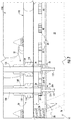
- connector assemblies 30, 32 are included, which connect the PCB 20 and the heat sink 140 via the first and second leads 134, 136.
- the connector assemblies 30, 32 each include lead seals 148 and connectors 34, 36.
- the first and second leads 134, 136 pass through the base plate 142 and the PCB 20 and are each secured to the PCB 20 by respective first and second connectors 34, 36.
- the base plate 142 defines a first through hole 144 and a second through hole 146 that are respectively aligned with a first board hole 24 and a second board hole 26 defined in the PCB 20.
- a lead seal 148 is secured within a corresponding one of the first and second through holes 144, 146 and defines a passage 149 for receiving and sealing about an outer surface of a respective one of the first and second leads 134, 136.
- Each of the lead seals 148 may also form a seal with an upper surface of the PCB 20 about a respective one of the first and second board holes 24, 26.
- An exemplary lead seal is available from Delphi Automotive LLP under part number 15366021.
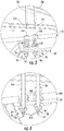
- the first connector 34 is positioned over the first board hole 24 and receives an exposed end portion 135 of the first lead 134 to form an electrical connection between the first lead 134 and the PCB 20.
- the second connector 36 is positioned over the second board hole 26 and receives an exposed end portion 137 of the second lead 136 to form an electrical connection between the second lead 136 and the PCB 20.
- Each of the first and second connectors 34, 36 allows a respective one of the first and second leads 134, 136 to pass through an opening 312 defined in a base 310 and to be captured between opposed legs 314.
- the opening 312 may be sized and dimensioned to allow an exposed end portion (e.g., first exposed end portion 135 or second exposed end 137) to pass through the base 310 while preventing the entire lead (e.g., first lead 134 or second lead 136) from passing through the base 310.
- the opposed legs 314 allow the respective exposed end portion 135, 137 to pass through in a first direction (e.g., down as shown in FIG.
- Such a connector allows one of the first and second leads 134, 136 to be attached to the PCB 20 in a single "push-in" step without additional soldering to form an electrical connection between the driver 130 and the PCB 20.
- suitable connectors are available from AVX Corporation under part numbers 70-9296-001-103-006 and 70-9296-001-123-006.
- the lens 50 is disposed over the PCB 20 and secured to the baseplate 142 with fasteners 58 (one shown).
- the lens 50 may form a seal with the baseplate 142 about the PCB 20 to seal or substantially seal the PCB 20 from the environment.
- a gasket or seal (not explicitly shown) may be positioned between the baseplate 142 and the lens 50 to form a seal between the baseplate 142 and the lens 50.
- the lens 50, the base plate 142, and the lead seals 148 may isolate the PCB 20 including the LEDs 40 within a cavity 52 defined between the lens 50 and the base plate 142.
- the PCB 20 and LEDs 40 are isolated from the environment surrounding the lighting fixture 100 while permitting energy to pass from the driver 130 to the LEDs 40.
- light generated by the LEDs 40 passes through the lens 50 and heat from the PCB 20, LEDs 40, lens 50, and reflector 150 passes through the base plate 142 and into the heat sink 140.
- Isolating the PCB 20 and the LEDs 40 may increase the service life of the PCB 20 and the LEDs 40.
- isolating the PCB 20 and the LEDs 40 may enhance the performance of the PCB 20 and the LEDs 40.
- the cavity may be a vacuum or may include an gas, e.g., an inert gas, at a pressure greater than an environment surrounding the light generating assembly 10.
- the reflector 150 is secured to the baseplate 142 with the lens 50 positioned within an opening 152 in the reflector 150.
- the lens 50 may direct light generated by the LEDs 40 into the reflector 150 such that light generated by the LEDs 40 is directed in a desired pattern.
- the lens 50 may also diffuse or filter light generated by the LEDs 40.
- the first and second leads 134, 136 have a portion of an insulator of the respective lead 134, 136 removed or striped to expose a conductor of the respective lead 134, 136 as an exposed end portion 135, 137, respectively.
- the exposed end portion 135 of the first lead 134 is then passed through the first through hole 144 in the base plate 142, a passage 149 of one of the lead seals 148, the first board hole 24 in the PCB 20, and between the legs 314 of the first connector 34.
- the exposed end portion 137 of the second lead 136 is then passed through the second through hole 146 in the base plate 142, a passage 149 of the other the lead seal 148, the second board hole 26 in the PCB 20, and captured between the legs 314 of the second connector 36.
- the PCB 20 can be secured to the base plate 142 before or after the first and second leads 134, 136 are captured between the legs 314 of the first and second connectors 34, 36, respectively.
- the lens 150 can be secured to the base plate 142 before or after the first and second leads 134, 136 being captured in the first and second connectors 34, 36, respectively.
- the exposed end portion 135 of the first lead 134 can be passed through the first board hole 24 in the PCB 20 and captured between the legs 314 of the first connector 34 and the exposed end portion 137 of the second lead 136 can be passed through the second board hole 26 in the PCB 20 and captured between the legs 134 of the second connector 36.
- the other end of the leads 134, 136 are each passed through a passage 149 of a lead seal 148 that is positioned within one of the first or second through holes 144, 146 in the base plate 142.
- the PCB 20 can then be secured to the base plate 142 and the lens 150 can be secured to the base plate 142 over the PCB 20.
Landscapes
- Engineering & Computer Science (AREA)
- General Engineering & Computer Science (AREA)
- Microelectronics & Electronic Packaging (AREA)
- Arrangement Of Elements, Cooling, Sealing, Or The Like Of Lighting Devices (AREA)
- Non-Portable Lighting Devices Or Systems Thereof (AREA)
Applications Claiming Priority (1)
| Application Number | Priority Date | Filing Date | Title |
|---|---|---|---|
| US15/258,582 US20180066834A1 (en) | 2016-09-07 | 2016-09-07 | Lighting fixture connection assembly |
Publications (1)
| Publication Number | Publication Date |
|---|---|
| EP3293452A1 true EP3293452A1 (de) | 2018-03-14 |
Family
ID=59968910
Family Applications (1)
| Application Number | Title | Priority Date | Filing Date |
|---|---|---|---|
| EP17189653.3A Withdrawn EP3293452A1 (de) | 2016-09-07 | 2017-09-06 | Leuchtenverbindungsanordnung |
Country Status (2)
| Country | Link |
|---|---|
| US (1) | US20180066834A1 (de) |
| EP (1) | EP3293452A1 (de) |
Families Citing this family (3)
| Publication number | Priority date | Publication date | Assignee | Title |
|---|---|---|---|---|
| USD838894S1 (en) * | 2016-04-15 | 2019-01-22 | Zopoise Technology (Zhuzhou) Co., Ltd. | High bay lamp |
| USD803460S1 (en) * | 2016-04-22 | 2017-11-21 | Hubbell Incorporated | Bay luminaire |
| CN109855021A (zh) * | 2019-01-04 | 2019-06-07 | 嘉兴星创科技有限公司 | 一种led诱鱼灯 |
Citations (4)
| Publication number | Priority date | Publication date | Assignee | Title |
|---|---|---|---|---|
| US20100277917A1 (en) * | 2009-05-01 | 2010-11-04 | Xinxin Shan | Electrically insulated led lights |
| DE102010014128A1 (de) * | 2010-04-07 | 2011-10-13 | Vivid Chi Matter And Light Gmbh | Pendelleuchte |
| EP2554895A1 (de) * | 2010-03-30 | 2013-02-06 | Toshiba Lighting&Technology Corporation | Röhrenlampe und beleuchtungsausrüstung damit |
| US20140139108A1 (en) * | 2012-11-16 | 2014-05-22 | Permlight Products, Inc. | Light emitting apparatus |
-
2016
- 2016-09-07 US US15/258,582 patent/US20180066834A1/en not_active Abandoned
-
2017
- 2017-09-06 EP EP17189653.3A patent/EP3293452A1/de not_active Withdrawn
Patent Citations (4)
| Publication number | Priority date | Publication date | Assignee | Title |
|---|---|---|---|---|
| US20100277917A1 (en) * | 2009-05-01 | 2010-11-04 | Xinxin Shan | Electrically insulated led lights |
| EP2554895A1 (de) * | 2010-03-30 | 2013-02-06 | Toshiba Lighting&Technology Corporation | Röhrenlampe und beleuchtungsausrüstung damit |
| DE102010014128A1 (de) * | 2010-04-07 | 2011-10-13 | Vivid Chi Matter And Light Gmbh | Pendelleuchte |
| US20140139108A1 (en) * | 2012-11-16 | 2014-05-22 | Permlight Products, Inc. | Light emitting apparatus |
Also Published As
| Publication number | Publication date |
|---|---|
| US20180066834A1 (en) | 2018-03-08 |
Similar Documents
| Publication | Publication Date | Title |
|---|---|---|
| US11009218B2 (en) | Surface mounted light fixture and heat dissipating structure for same | |
| US8602608B2 (en) | Light module | |
| US10203103B2 (en) | LED luminaire having enhanced thermal management | |
| CN101952638B (zh) | 发光二极管模块和互连系统 | |
| US7976335B2 (en) | LED connector assembly with heat sink | |
| US8777449B2 (en) | Lighting devices comprising solid state light emitters | |
| US8894253B2 (en) | Heat transfer bracket for lighting fixture | |
| US8714785B2 (en) | Cap, socket device, and luminaire | |
| US10234127B2 (en) | LED luminaire having enhanced thermal management | |
| US11898706B2 (en) | Illuminating device | |
| US20070242461A1 (en) | LED based light engine | |
| CA2735632C (en) | Multiple led bulb with thermal management features | |
| US20120051068A1 (en) | Light module | |
| US9781798B2 (en) | LED-based illumination systems having sense and communication capability | |
| US8878435B2 (en) | Remote thermal compensation assembly | |
| MX2012004674A (es) | Accesorio luminoso de pared. | |
| US8492977B2 (en) | Lighting unit using a retro-formed component | |
| US10012371B2 (en) | Solid state lighting apparatus including isolated solid state lighting driver circuits and related solid state lighting covers, housings, and lenses | |
| US9759387B2 (en) | Dual optical interface LED lamp | |
| US12018822B2 (en) | Surface mounted light fixture and heat dissipating structure for same | |
| EP3293452A1 (de) | Leuchtenverbindungsanordnung | |
| EP3141086B1 (de) | Led-basierte beleuchtungsvorrichtung mit reflektorelement und detektor für ein kommunikationssystem | |
| EP3611429A1 (de) | Led-basierte beleuchtungssysteme mit erfassungs- und kommunikationsfähigkeit | |
| CN202629679U (zh) | Led灯系统 | |
| JP2016122557A (ja) | Led照明装置 |
Legal Events
| Date | Code | Title | Description |
|---|---|---|---|
| PUAI | Public reference made under article 153(3) epc to a published international application that has entered the european phase |
Free format text: ORIGINAL CODE: 0009012 |
|
| STAA | Information on the status of an ep patent application or granted ep patent |
Free format text: STATUS: THE APPLICATION HAS BEEN PUBLISHED |
|
| AK | Designated contracting states |
Kind code of ref document: A1 Designated state(s): AL AT BE BG CH CY CZ DE DK EE ES FI FR GB GR HR HU IE IS IT LI LT LU LV MC MK MT NL NO PL PT RO RS SE SI SK SM TR |
|
| AX | Request for extension of the european patent |
Extension state: BA ME |
|
| STAA | Information on the status of an ep patent application or granted ep patent |
Free format text: STATUS: REQUEST FOR EXAMINATION WAS MADE |
|
| 17P | Request for examination filed |
Effective date: 20180914 |
|
| RBV | Designated contracting states (corrected) |
Designated state(s): AL AT BE BG CH CY CZ DE DK EE ES FI FR GB GR HR HU IE IS IT LI LT LU LV MC MK MT NL NO PL PT RO RS SE SI SK SM TR |
|
| RIC1 | Information provided on ipc code assigned before grant |
Ipc: F21V 27/02 20060101AFI20181217BHEP Ipc: F21V 29/70 20150101ALI20181217BHEP Ipc: F21V 23/06 20060101ALI20181217BHEP Ipc: F21S 8/06 20060101ALI20181217BHEP Ipc: F21V 21/008 20060101ALI20181217BHEP Ipc: F21S 8/04 20060101ALI20181217BHEP |
|
| GRAP | Despatch of communication of intention to grant a patent |
Free format text: ORIGINAL CODE: EPIDOSNIGR1 |
|
| STAA | Information on the status of an ep patent application or granted ep patent |
Free format text: STATUS: GRANT OF PATENT IS INTENDED |
|
| INTG | Intention to grant announced |
Effective date: 20190206 |
|
| STAA | Information on the status of an ep patent application or granted ep patent |
Free format text: STATUS: THE APPLICATION IS DEEMED TO BE WITHDRAWN |
|
| 18D | Application deemed to be withdrawn |
Effective date: 20190618 |