EP3293500A2 - Balance dotée des coupelles permettant le pesage et la décharge des composants de fibres sur une bande de mixage - Google Patents
Balance dotée des coupelles permettant le pesage et la décharge des composants de fibres sur une bande de mixage Download PDFInfo
- Publication number
- EP3293500A2 EP3293500A2 EP17189892.7A EP17189892A EP3293500A2 EP 3293500 A2 EP3293500 A2 EP 3293500A2 EP 17189892 A EP17189892 A EP 17189892A EP 3293500 A2 EP3293500 A2 EP 3293500A2
- Authority
- EP
- European Patent Office
- Prior art keywords
- retaining
- flaps
- flap
- container
- bottom flap
- Prior art date
- Legal status (The legal status is an assumption and is not a legal conclusion. Google has not performed a legal analysis and makes no representation as to the accuracy of the status listed.)
- Withdrawn
Links
- 238000005303 weighing Methods 0.000 title claims abstract description 21
- 239000000470 constituent Substances 0.000 title 1
- 239000000835 fiber Substances 0.000 claims abstract description 80
- 230000000717 retained effect Effects 0.000 claims abstract description 8
- 230000007246 mechanism Effects 0.000 claims description 24
- 230000001133 acceleration Effects 0.000 claims description 9
- 239000002184 metal Substances 0.000 claims description 2
- 238000009826 distribution Methods 0.000 description 18
- 230000014759 maintenance of location Effects 0.000 description 9
- 239000000463 material Substances 0.000 description 8
- 238000004519 manufacturing process Methods 0.000 description 4
- 238000009987 spinning Methods 0.000 description 4
- 230000009471 action Effects 0.000 description 3
- 229920000742 Cotton Polymers 0.000 description 2
- 230000035508 accumulation Effects 0.000 description 2
- 238000009825 accumulation Methods 0.000 description 2
- 239000002657 fibrous material Substances 0.000 description 2
- 239000000203 mixture Substances 0.000 description 2
- 239000000126 substance Substances 0.000 description 2
- 230000007704 transition Effects 0.000 description 2
- 239000002699 waste material Substances 0.000 description 2
- 230000005540 biological transmission Effects 0.000 description 1
- 239000003795 chemical substances by application Substances 0.000 description 1
- 230000000694 effects Effects 0.000 description 1
- 230000001788 irregular Effects 0.000 description 1
- 239000004745 nonwoven fabric Substances 0.000 description 1
- 230000008092 positive effect Effects 0.000 description 1
- 238000002360 preparation method Methods 0.000 description 1
- 238000007493 shaping process Methods 0.000 description 1
- 239000004753 textile Substances 0.000 description 1
Images


Classifications
-
- G—PHYSICS
- G01—MEASURING; TESTING
- G01G—WEIGHING
- G01G21/00—Details of weighing apparatus
- G01G21/22—Weigh pans or other weighing receptacles; Weighing platforms
-
- D—TEXTILES; PAPER
- D01—NATURAL OR MAN-MADE THREADS OR FIBRES; SPINNING
- D01G—PRELIMINARY TREATMENT OF FIBRES, e.g. FOR SPINNING
- D01G13/00—Mixing, e.g. blending, fibres; Mixing non-fibrous materials with fibres
-
- G—PHYSICS
- G01—MEASURING; TESTING
- G01G—WEIGHING
- G01G13/00—Weighing apparatus with automatic feed or discharge for weighing-out batches of material
- G01G13/16—Means for automatically discharging weigh receptacles under control of the weighing mechanism
- G01G13/18—Means for automatically discharging weigh receptacles under control of the weighing mechanism by valves or flaps in the container bottom
Definitions
- the present invention relates to a tray scale for weighing and dropping fiber components onto a mixing belt having an open-topped container comprising a plurality of side walls and a bottom, the bottom being formed by a single pivotally hinged bottom flap formed from one adjacent one of the side walls Closed position is rotatable in an open position folded away from this side wall, or wherein the bottom is formed by two rotatably hinged bottom flaps, which are rotatable away from a contiguous inner closed position away from each other in an outer open position.
- the present invention relates to a tray scale for weighing and dropping fiber components onto a mixing belt having an upwardly open container comprising a plurality of side walls and a bottom, the bottom being formed by a single pivotally hinged bottom flap formed from one on one of the Side walls adjacent closed position in a folded away from this side wall open position is rotatable, or wherein the bottom is divided into two longitudinally container and is formed by two rotatably hinged bottom flaps, which are rotatable from an adjacent inner closed position away from each other in an outer open position, with a control mechanism for Closing and opening the single bottom flap or the two bottom flaps of the two-part bottom and with an electronic control for controlling the control mechanism.
- the present invention relates to a mixing device for fiber components with a mixing belt and at least one tray balance arranged above the mixing belt.
- Mixing devices are used to produce accurate and intensive blends, for example, for the spinning and nonwovens industries.
- Mixed are various chemical fibers, cotton and chemical fibers, various recovered waste fibers, cotton and recovered waste fibers.
- tray scales which are usually arranged centrally above the mixing belt, and this leads to high fiber accumulations in a short time in the case of several machines arranged one behind the other. This can be disadvantageous misalignments by not completely emptied scale container and in the middle to high material densities occur with disturbances in the material transport and in the opening on the downstream mixing roller.
- a bowl balance is proposed for weighing and dropping fiber components onto a mixing belt.
- Such tray scales are especially intended for weighing box feeders in the spinning and non-food industries.
- the bowl scale comprises an open-topped container.
- the container has a plurality of side walls and a bottom split in the container longitudinal direction.
- the bottom is formed by a single rotatably hinged bottom flap, which is rotatable from a voltage applied to one of the side walls closed position in an away from this side wall open position.
- the bottom is divided into two parts in the container longitudinal direction and formed by two, in particular on the side walls, rotatably hinged bottom flaps.
- the two bottom flaps are rotatable away from a contiguous inner closed position away from each other in an outer open position. In the closed position, the container is closed at the bottom, so that fiber components can be filled through its upper opening and then weighed. In the open position, the container is open at the bottom, so that the filled and weighed fiber components can be dropped onto the mixing belt.
- the single bottom flap or at least one of the two bottom flaps of the two-piece bottom has at its bottom surface, i. in the area of the bottom surface, at least in one area a retaining means.
- the retaining means is designed and / or arranged such that by means of the latter when opening the associated bottom flap part of the fiber components can be retained by means of positive and / or frictional engagement up to a partial opening angle.
- the amount and the location of the distributable fiber components can be influenced as a function of the opening angle.
- the holding means up to a partial opening angle in the interior of the container. Only when the re-energizing of the predetermined partial opening angle is exceeded, the retained fiber components can overcome the retention means and be unloaded on the mixing belt. This is further due to the rotation of the at least one bottom flap at a position displaced to the first unloading in the transverse direction of the mixing belt.
- the retention means can thus advantageously achieve a more homogeneous distribution of the fiber components in the transverse direction of the mixing belt. In this way, a complete emptying of the scale can be ensured because bulk cones are avoided. Furthermore, disturbances in material transport are avoided. Furthermore, a very cost-effective scale can be created hereby, by means of which a very good distribution can be achieved.
- the retaining means is spaced from the bulk edge. In this way it can be ensured that the fiber components located between the pouring edge and the retaining means are dropped off directly and the fiber components arranged behind the retaining means or in the region of the retaining means are retained by the latter up to a certain opening angle. As a result, differently sized amounts of the fiber components can be dropped in different areas of the mixing belt.
- the retaining means is a retaining structure.
- the retention structure can be, for example, a corrugation, a grain and / or a corrugation, ie wave-shaped structure.
- the retaining structure is designed such that it preferably has a higher roughness and / or a higher coefficient of friction compared to a retention agent-free region of the bottom surface.
- the retaining means is at least one retaining element.
- the retaining element may be, for example, a survey and / or depression.
- a plurality of retaining elements arranged one behind the other can form a retaining structure.
- the retaining elements preferably extend parallel to the longitudinal center plane and / or over the entire length of the associated bottom flap, i. in particular the individual bottom flap or one of the two bottom flaps of the two-part bottom.
- the retaining structure and / or the retaining element is formed integrally with the bottom flap.
- the bottom flap may for example be pressed so that it has a waveform.
- the retaining structure and / or the retaining element may be incorporated in the bottom surface of the bottom flap, which would be the case in particular in the case of a retaining structure designed as a corrugation.
- the retaining structure and / or the retaining element connected to the bottom flap in particular glued, screwed, welded and / or pressed, is.
- the retaining structure and / or the retaining element has a, in particular planar, concave and / or convex retaining surface, which is preferably arranged perpendicular to the bottom surface or is inclined to this.
- the retaining surface is formed as a surface of the retaining structure. In this case, the retaining surface may have a regular and / or irregular structure.
- the individual bottom flap or at least one of the two bottom flaps of the two-part bottom is at least partially formed as a sheet metal bent part.
- the single bottom flap or at least one of the two bottom flaps of the two-part bottom has a constant wall thickness.
- the individual bottom flap or at least one of the two bottom flaps of the two-part bottom is shaped and / or so assembled from several individual parts, in particular welded together, that the bottom flap in a region of the retaining element and / or the retention structure has forming form.
- the retaining surface of the retaining element is provided with the retaining structure.
- the retaining element of one of the two bottom flaps extends into the region of the other bottom fl ap.
- At least one of the bottom flaps starting from the pouring edge outwards, has a plurality of retaining means, in particular retaining structures and / or retaining elements, arranged one behind the other.
- the bowl scale comprises an open-topped container.
- the container has a plurality of side walls and a bottom split in the container longitudinal direction.
- the bottom is divided into two parts in the container longitudinal direction and formed by two, in particular on the side walls, rotatably hinged bottom flaps.
- the two bottom flaps are rotatable away from a contiguous inner closed position away from each other in an outer open position. In the closed position, the container is closed at the bottom, so that through its upper opening Fiber components can be filled and then weighed. In the open position, the container is open at the bottom, so that the filled and weighed fiber components can be dropped onto the mixing belt.
- the two bottom flaps are asymmetrically formed with respect to each other such that they have different sized bottom surfaces.
- the container is not filled homogeneously with the fiber components. Instead, an uneven distribution of the fiber components already forms inside the container. If, for example, when filling a one-sided increased filling of the container takes place, it is advantageous if in this area the bottom flap is arranged with the lower bottom surface, since the filling height is higher in this area. In the area of the lower filling level, therefore, the bottom flap with the larger bottom surface is arranged.
- both bottom flaps take a mutually aligned volume of the fiber components.
- a more homogeneous distribution of the fiber components in the transverse direction of the mixing belt during unloading can be effected as a result.
- the unloading location in the transverse direction of the mixing belt at the beginning of the opening phase can be influenced by the two mutually asymmetrical bottom flaps.
- the capacity of the two bottom flaps can be influenced.
- the two bottom surfaces are of equal length to each other in the longitudinal direction of the container and / or in the transverse direction of the container. As a result, advantageously, the capacity of the respective bottom flap can be influenced.
- the two bottom flaps abut each other in the closed position in the region of a parting plane at least in one section. In this way it can be ensured that the two bottom flaps close securely in their area of contact, so that the fiber components are held inside the container.
- the parting plane has a translatory offset to a longitudinal center plane of the container. In this way, a correspondingly asymmetrical design of the two bottom flaps can be achieved so that they have a mutually different volume of the container. In this way, an inhomogeneous filling of the scale can be counteracted, which in turn has a positive effect on a homogeneous distribution of the fiber components in the transverse direction of the mixing belt.
- the bottom surface, in particular a first subregion, of at least one of the two bottom flaps is inclined in such a way that, in a closed cross-sectional view of the container, it falls off and / or rises in the closed position from the pouring edge.
- the ejection angle can be influenced by the fiber components emerge from the discharge opening in the opening phase of the tray scale.
- the bottom surface of at least one of the two bottom flaps has a second partial region adjoining the first partial region.
- this second portion is for inclined first portion opposite, so that a kink is formed between these two.
- the bottom surface is preferably flat, concave and / or convex.
- At least one of the two bottom flaps has a side surface adjoining the respective bottom surface.
- the side surface is preferably inclined so that, with the bottom flap closed, the container tapers in the direction of the bottom, preferably funnel-shaped.
- the bottom flaps are articulated on two opposite side surfaces, in particular front side surfaces, in a respective articulation point.
- the articulation points of the two bottom flaps are arranged symmetrically to the longitudinal center plane. Additionally or alternatively, it is advantageous if the two bottom flaps are pivotable about the same maximum opening angle.
- the two bottom flaps have a maximum opening width formed between their respective pouring edge and the dividing plane.
- the two bottom flaps have maximum opening widths of different sizes.
- the tray scale comprises an upwardly open container comprising a plurality of sidewalls and a bottom, the bottom being formed by a single pivotally hinged bottom flap formed from one at one of the Side walls adjacent closed position is rotatable in a folded away from this side wall open position, or wherein the bottom is divided into two longitudinally spaced container and is formed by two rotatably hinged bottom flaps, which are rotatable away from a contiguous inner closed position away in an outer open position.
- the tray scale comprises a control mechanism for closing and opening the single bottom flap or the two bottom flaps of the two-part bottom.
- the tray scale has an electronic controller for controlling the control mechanism.
- the control mechanism is designed and / or the controller is programmed such that a rotational speed and / or a rotational acceleration of the individual bottom flap or at least one of the two bottom flaps of the two-part bottom depending on the opening angle is controllable.
- the control mechanism is designed and / or the controller programmed so that the opening angle of the individual bottom flap or at least one of the two bottom flaps of the two-part bottom is controlled as a function of time. In this way, advantageously, the discharge quantity of the fiber components in the mixing belt transverse direction in a partial region of the mixing belt can be influenced.
- controller is programmed in such a way that the rotational speed and / or the rotational acceleration are kept constant, increased and / or reduced at least in an angular interval when the bottom flap is opened.
- control mechanism and / or the control are designed such that the opening angle can be adjusted and / or controlled steplessly or in discrete steps.
- the controller is programmed such that the bottom flap is opened up to a first angular position and held in this first angular position within a first time window and / or subsequently opened up to a second angular position and / or in this second angular position held within a second time window.
- control mechanism comprises at least one, in particular discretely or continuously adjustable, actuator and / or that the two bottom flaps have a common actuator or in each case a separately controllable actuator.
- the scale comprises a, in particular mechanical, pneumatic and / or hydraulic, control mechanism which is designed such that the rotational speed of at least one bottom flap in dependence of the opening angle is controllable.
- the tray balance comprises an electronic control which is programmed such that the rotational speed of at least one bottom flap is controllable as a function of the opening angle.
- the scale has a weighing unit, by means of which the filled into the container fiber components can be weighed.
- the two bottom flaps have a common actuator by means of which both bottom flaps can be actuated simultaneously.
- the bottom flaps each have a separately controllable actuator. As a result, the two bottom flaps can be controlled independently of each other, so that each bottom flap the amount of fiber components to be thrown off can be influenced.
- a mixing device for fiber components with a mixing belt and at least one tray balance arranged above the mixing belt.
- the scale is formed according to the preceding description, wherein said components may be present individually or in any combination.
- a more homogeneous distribution of the fiber components can advantageously be achieved in the transverse direction of the mixing belt.
- the mixing device comprises at least two shell balances arranged one behind the other in the longitudinal extension of the mixing belt and / or stationary.
- the at least two tray scales arranged one behind the other are rotated by 180 ° relative to each other about a vertical axis of the mixing belt.
- the dividing plane of the first scale can thus be offset to the right in comparison to the central axis of the mixing strip and the second mixing balance, which is however twisted by 180 °, can be offset to the right.
- the two shell scales are arranged offset to a transverse axis of the mixing belt.
- FIG. 1 shows a tray balance 1 for weighing and dropping fiber components on a mixing belt not shown here.
- the tray scales comprises an upwardly open container 2. About an upper opening 3, this container 2 can be filled by a weighing box feeder also not shown here with fiber components, such as a textile fiber mixture of fiber flakes.
- the container 2 comprises a plurality of side walls 4, 5, 6, 7, which form a closed container frame 8.
- the container frame 8 is formed rectangular, which has two opposite longitudinal side walls 4, 5 and two opposite end-side side walls 6, 7.
- the longitudinal side walls 4, 5 are in this case longer than the two end-side side walls 6, 7 are formed.
- the container 2 comprises a bottom 9. This closes the container frame 8 downwards.
- the bottom 9 is formed by two bottom flaps 10, 11.
- the two bottom flaps 10, 11 are rotatably mounted on the container frame 8, in particular according to the present embodiment, on the two end-side side walls 6, 7, in a respective pivot point 12, 13.
- the two bottom flaps 10, 11 are rotated away from each other outwards.
- the rotational movement of the two bottom flaps 10, 11 is controlled by a controller 39.
- FIGS. 2a and 2b shows the two pivot points 12, 13 of the two bottom flaps 10, 11 arranged symmetrically to a longitudinal center plane 15 of the scale 1 scale.
- the actuator 14 is according to the present embodiment is not directly connected to the respective bottom flap 10, 11, but indirectly via a not explained in detail mechanism explained. Due to the mutually symmetrical force application points 16, 17 and articulation points 12, 13, the two bottom flaps are each rotatable by a same maximum opening angle ⁇ .
- the two bottom flaps 10, 11 formed asymmetrically to each other. As a result, these have different sized compared to each other bottom surfaces 18, 19. As in particular from FIG. 2a shows, therefore, one of the two bottom flaps 10 is narrower and the other bottom flap 11 is wider. In the in FIG. 2a shown closed position, the two bottom flaps 10, 11 together on a substantially to the longitudinal center plane 15 of the container 2 symmetrical basic shape. However, the two bottom flaps 10, 11 are different in size, so that they are asymmetrical to each other. For this purpose, a parting plane 20 of the two bottom flaps 10, 11 does not extend in the longitudinal center plane 15. Instead, the parting plane 20 points according to FIG FIG. 2a to the longitudinal center plane 15 of the container 2 to a translational offset V on.
- the fiber component located in the container 2 can advantageously be achieved more homogeneously over the width of the mixing tape not shown here.
- a bulk cone is formed by the tray scales, which are usually arranged centrally above the mixing belt. This can result in several consecutively arranged tray scales in a short time to high fiber accumulations.
- disadvantageous misalignments by not fully emptied shell scales and medium to high material densities with disturbances in the material transport and in the opening at the downstream mixing roller can occur in a disadvantageous manner.
- FIG. 1 and 2a shows, the two bottom surfaces 18, 19 of the two bottom flaps 10, 11 to each other in the container longitudinal direction of equal length. Due to the asymmetrical design, however, they are in the transverse direction of the container FIG. 2a formed differently wide.
- the first bottom surface 18 of the first bottom flap 10 is inclined with respect to the horizontal.
- the first bottom surface 18 accordingly drops outward from a pouring edge 21 of the bottom flap, ie in the direction of the first left-hand side wall 4.
- the second bottom surface 19 of the second bottom flap 11 has a first and second portion 23, 24.
- the first subregion 23 is formed analogously to the first bottom surface 18 of the first bottom flap 10.
- the first portion 23 falls from the second pouring edge 22, starting from the outside.
- the second portion 24 is inclined in opposite directions compared to the first portion 23.
- a kink 25 is formed between the first and second partial regions 23, 24.
- the second bottom surface 19 has a substantially concave shape.
- the two bottom flaps 10, 11 in addition to their bottom surfaces 18, 19 each have a side surface 26, 27.
- the two side surfaces 26, 27 close to the outside to the respective bottom surface 18, 19 at.
- the two side surfaces 26, 27 are inclined relative to each other with respect to a vertical, so that these in the in FIG. 2a shown side view substantially funnel-shaped in the direction of the two bottom surfaces 18, 19 run.
- the bottom surfaces 18, 19, in particular their subregions 23, 24, and / or the side surfaces 26, 27 may be formed as a flat surface as shown. However, it is also conceivable that they have a convex or concave shape in cross section.
- an edge may be formed at the transition between the respective side surfaces 26, 27 into the respective bottom surfaces 18, 19, an edge may be formed. Alternatively, the transition can also be formed by a rounding.
- FIG. 2b shows FIG. 2b the tray balance 1 in the open position.
- the two bottom flaps 10, 11 are rotated away from each other by their maximum opening angle ⁇ .
- each of the two bottom flaps 10, 11 on between their respective bulkhead 21, 22 and the parting plane 20 formed maximum opening width A, B on. Due to the asymmetrical configuration of the two bottom flaps 10, 11, the maximum opening widths A, B are different in size. According to the present embodiment, the maximum opening width A of the first bottom flap 10 is smaller than the maximum opening width B of the second bottom flap 11.
- the two could be in FIG. 1 .
- 2a and 2b illustrated bottom flaps 10, 11 in an embodiment not shown here but also be symmetrical to each other.
- the bottom 9 is formed by a single rotatably hinged bottom flap, which consists of a voltage applied to one of the side walls closed position is rotatable in an open position folded away from this side wall.
- FIGS. 3a, 3b, 3c an embodiment of a bottom flap 11 is shown in different rotational positions.
- the bottom flap 11 may be a single rotatably hinged bottom flap 11 which is rotatable from a voltage applied to one of the side walls 4 closed position in an away from this side wall 4 open position.
- the bottom flap 11 may also be one of two bottom flaps of a bottom 9 divided into two parts in the container longitudinal direction. The two bottom flaps can be symmetrical or asymmetrical to one another.
- FIG. 3a shows the bottom flap 11 in the closed position. In this closed position, the illustrated bottom flap 11 cooperates with another bottom flap 10, such as in FIG. 2a shown.
- FIG. 3a shows the bottom flap 11 in the closed position. In this closed position, the illustrated bottom flap 11 cooperates with another bottom flap 10, such as in FIG. 2a shown.
- additional bottom flap 10 does not necessarily have to be formed asymmetrically to the illustrated bottom flap 11.
- bottom flap 11 also interact a substantially symmetrical from the outer basic shape bottom flap.
- the present not shown additional bottom flap 10 according to the in the FIGS. 1 and 2 illustrated embodiment formed.
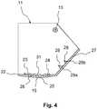
- it can also be a single bottom flap 11, which cooperates with one of the side walls 4. The above alternatives also apply to the FIG. 4 shown bottom flap 11 too.
- FIGS. 3a, 3b, 3c As well as 4 illustrated embodiments of the bottom flap 11 are for features that compared to the in FIG. 1 . 2a, 2b represented in its configuration and / or mode of action identical and / or at least comparable, the same reference numerals used. Unless these are explained again in detail, their design corresponds and / or mode of action of the embodiment and / or mode of action of the features already described above.
- FIG. 3a the bottom flap 11 on its bottom surface 19, a retaining means 28. That in the FIGS. 1 . 2a and 2b illustrated first embodiment, in particular the first and / or second bottom flap 10, 11, may also have a trained according to the following description retaining means 28.
- this retaining means 28 is formed as a retaining element 29.
- the retaining element 29 is spaced from the pouring edge 22.
- the retaining element 29 is formed as a survey. It preferably extends over the entire length of the associated bottom flap 11.
- the retaining element 29 may also be formed as a depression or shoulder.
- the retaining element 29 and the bottom surface 19 are formed in two parts.
- the retaining element 29 is therefore preferably fixedly or detachably connected to the bottom surface 19.
- the retaining element 29 may be welded to the bottom surface 19, screwed or glued.
- the retaining element 29 is formed integrally with the bottom surface 19 or else is formed by a corresponding shaping of the bottom surface 19.
- the retaining element 29 has according to FIG. 3a a retaining surface 30, by means of which a part of the fiber components can be retained when opening the container 2 up to a certain opening angle.
- the retaining surface 30 is planar according to the present embodiment. Alternatively, it is also conceivable that this is concave and / or convex.
- the retaining surface 30 is further inclined according to the present embodiment with respect to the associated bottom surface 19, in particular in the direction of the bulk edge 22.
- the retaining element 29 may also be designed such that the retaining surface 30 is inclined away from the pouring edge 22 or is also aligned perpendicular to the bottom surface 19.
- a plurality of retaining elements 29 may be arranged one behind the other. These can be identical to one another or else different, in particular of different sizes and / or shapes.
- the retaining means 28 is further a retaining structure 31.
- the retaining structure 31 is, for example, a corrugation, grain and / or a corrugation, which is arranged on the bottom surface 19.
- the retaining structure 31 may in this case be incorporated in the bottom surface 19.
- the bottom surface 19 may be roughened, for example, by appropriate processing.
- the retaining means 28 formed as a retaining structure 31 thus increases the adhesion between the bottom flap 11 and the fiber components 32.
- the retention structure 31 may also be formed by a plurality of retaining elements 29 arranged one behind the other.
- the retaining means 28, in particular the retaining element 29 and / or the retaining structure 31, therefore serve to be able to retain part of the fiber components 32 by means of positive and / or frictional engagement when the associated bottom flap 11 is opened up to a partial opening angle ⁇ .
- FIGS. 3a, 3b, 3c illustrated This is for example in the FIGS. 3a, 3b, 3c illustrated. Accordingly, in the in FIG. 3a illustrated closed position of the bottom flap 11 prevents that in conjunction with the present not shown second bottom flap 10 fiber components 32 can reach the arranged below the scale 1 scale Mischband.
- FIG. 3b shows the bottom flap 11 in an intermediate position in which it is rotated by a partial opening angle ⁇ .
- a first subset 33 of the fiber components 32 in the transverse direction of the mixing belt 34 in a first mixing belt area 35 poured.
- a second subset 36 of the fiber components 32 is retained in the interior of the container via the retaining means 28.
- the controller may be designed such that the rotational speed of the bottom flap 11 is controlled in dependence on the opening angle ⁇ , ⁇ .
- the rotational speed when opening the bottom flap 11 in a first angular interval for example, until in FIG. 3b shown partial opening angle ⁇ is smaller or larger than in one, for example, subsequent second angular interval.
- the control of the rotational speed as a function of the opening angle can be realized, for example, passively by a mechanical, pneumatic and / or hydraulic control mechanism.
- a transmission and / or an articulation between bottom flap 11 and actuator 14 are formed be that causes different rotational speeds depending on the opening angle.
- the scale 1 comprises an electronic control, by means of which the speed of the actuator 14 can be influenced in order to achieve the above effect.
- the illustrated bottom flap 11 in the region of the bottom surface 19 has a retaining structure 31.
- the retention structure 31 is configured in particular as ribbing, grain and / or corrugation.
- the bottom flap 11 has two protruding retaining elements 29a, 29b. These are arranged on the side surface 27 according to the present embodiment. Both the retaining elements 29a, 29b and the retaining structure 31 can be arranged in the region of the bottom surface 19 and / or side surface 27.
- the tray balance 1 comprises a control mechanism 38 for closing and opening the single bottom flap 11 of the one-piece bottom 9 or the two bottom flaps 10, 11 of the two-part bottom 9.
- the scale scales 1 the electronic control 39 for Controlling the control mechanism (cf. FIG. 1 ).
- the control mechanism 38 is designed and / or the controller 39 is programmed such that a rotational speed and / or rotational acceleration of the individual bottom flap 11 or at least one of the two bottom flaps 10, 11 of the two-part bottom 9 in dependence of the opening angle is controllable.
- control mechanism 38 is configured and / or the controller 39 programmed so that the opening angle of the individual bottom flap 11 or at least one of the two bottom flaps 10, 11 of the two-part bottom 9 is controlled as a function of time.
- the discharge of the Fiber components are influenced in cross-belt transverse direction in a portion of the mixing belt 34.
- a more homogeneous distribution of the fiber components in the transverse direction of the mixing belt 34 can be achieved.
- a complete emptying of the scale 1 can be ensured because bulk cones are avoided.
- disturbances in material transport are avoided.
- this can provide a very cost-effective scale 1, by means of which a very good distribution can be achieved.
- the controller 39 is programmed such that the rotational speed and / or the rotational acceleration during the opening of the at least one bottom flap 10, 11 kept constant at least in an angular interval, increased and / or reduced. It is also advantageous if the rotational speed and / or the rotational acceleration when opening the at least one base flap 10, 11 in a first angular interval is smaller or larger than in a second angular interval. It is advantageous if the control mechanism 38 and / or the control 39 are designed such that the opening angle can be adjusted and / or controlled steplessly or in discrete steps.
- the controller 39 is programmed such that the at least one bottom flap 10, 11 is opened to a first angular position and held in this first angular position within a first time window and / or then opened to a second angular position and / or is held in this second angular position within a second time window. It is also advantageous if the control mechanism 38 comprises at least the, in particular discretely or continuously adjustable, actuator 14 and / or that the two bottom flaps 10, 11 have a common actuator 14 or each having a separately controllable actuator 14.
Landscapes
- Physics & Mathematics (AREA)
- General Physics & Mathematics (AREA)
- Engineering & Computer Science (AREA)
- Textile Engineering (AREA)
- Nonwoven Fabrics (AREA)
- Details Of Rigid Or Semi-Rigid Containers (AREA)
Applications Claiming Priority (1)
| Application Number | Priority Date | Filing Date | Title |
|---|---|---|---|
| DE102016116784 | 2016-09-07 |
Publications (2)
| Publication Number | Publication Date |
|---|---|
| EP3293500A2 true EP3293500A2 (fr) | 2018-03-14 |
| EP3293500A3 EP3293500A3 (fr) | 2018-04-25 |
Family
ID=59829239
Family Applications (1)
| Application Number | Title | Priority Date | Filing Date |
|---|---|---|---|
| EP17189892.7A Withdrawn EP3293500A3 (fr) | 2016-09-07 | 2017-09-07 | Balance dotée des coupelles permettant le pesage et la décharge des composants de fibres sur une bande de mixage |
Country Status (3)
| Country | Link |
|---|---|
| US (1) | US10401213B2 (fr) |
| EP (1) | EP3293500A3 (fr) |
| DE (1) | DE102017120646A1 (fr) |
Families Citing this family (1)
| Publication number | Priority date | Publication date | Assignee | Title |
|---|---|---|---|---|
| CN113417019B (zh) * | 2021-07-09 | 2022-11-08 | 天津工业大学 | 一种裂离型卷曲纺粘长丝及其制备方法和应用 |
Family Cites Families (7)
| Publication number | Priority date | Publication date | Assignee | Title |
|---|---|---|---|---|
| US3295728A (en) * | 1964-06-10 | 1967-01-03 | Joseph W Hochmuth | Gravel hopper manual dump |
| SE452303B (sv) * | 1986-03-12 | 1987-11-23 | Consilium Marine Ab | Utmatningsanordning i godsfickor |
| DK162958C (da) * | 1989-12-13 | 1992-05-25 | Gunnar Christian Petersen | Vejeskaal til afvejning af delportioner af et produkt og kombinationsvejemaskine med et antal saadanne vejeskaale |
| DE4212997A1 (de) | 1992-04-18 | 1993-10-21 | Truetzschler Gmbh & Co Kg | Vorrichtung zum Speisen und Wiegen von Textilfasern, insbesondere Baumwolle und Chemiefasern |
| DE9303096U1 (de) | 1993-03-03 | 1994-03-31 | Siemens AG, 80333 München | Wägevorrichtung |
| DE102004048222A1 (de) | 2004-09-30 | 2006-04-06 | Trützschler GmbH & Co KG | Vorrichtung zum Mischen von Faserkomponenten, z.B. Faserflocken, insbesondere in der Spinnereivorbereitung, Faservliesherstellung o. dgl. |
| DE102014111290A1 (de) | 2014-08-07 | 2016-02-11 | Trützschler GmbH & Co Kommanditgesellschaft | Vorrichtung zum Mischen von Faserkomponenten |
-
2017
- 2017-09-06 US US15/696,862 patent/US10401213B2/en not_active Expired - Fee Related
- 2017-09-07 EP EP17189892.7A patent/EP3293500A3/fr not_active Withdrawn
- 2017-09-07 DE DE102017120646.9A patent/DE102017120646A1/de not_active Withdrawn
Also Published As
| Publication number | Publication date |
|---|---|
| US20180066979A1 (en) | 2018-03-08 |
| DE102017120646A1 (de) | 2018-03-08 |
| US10401213B2 (en) | 2019-09-03 |
| EP3293500A3 (fr) | 2018-04-25 |
Similar Documents
| Publication | Publication Date | Title |
|---|---|---|
| EP2995183B1 (fr) | Dispositif de dosage | |
| AT503082B1 (de) | System zur abgabe von schüttgut sowie behälter mit einem solchen schüttgutabgabesystem | |
| DE102007050268A1 (de) | Vorrichtung zum dosierten Mischen von schüttbaren Materialkomponenten | |
| EP1952706A1 (fr) | Magasin de vidage et procédé de vidage de récipients remplis de produits en forme de tige, en particulier récipients en forme de colonne | |
| EP2359704B1 (fr) | Dispositif et procédé de réunion de flux de matière, notamment pour une cartouche de vidage | |
| EP2120615B1 (fr) | Magasin de vidage pour un dispositif de vidage de conteneur conçu pour vider des conteneurs remplis de produits en forme de tige | |
| EP1221516A2 (fr) | Procédé et dispositif pour appliquer une couche de mortier mince | |
| DE3601104A1 (de) | Vorrichtung zum herstellen von beutelpackungen | |
| EP3192755B1 (fr) | Dispositif d'acheminement dote d'un limiteur de debit | |
| EP0045839A1 (fr) | Dispositif de dosage pour matériau en vrac sous forme de poussière ou de poudre ou capable de s'écouler | |
| EP3293500A2 (fr) | Balance dotée des coupelles permettant le pesage et la décharge des composants de fibres sur une bande de mixage | |
| DE102008000730A1 (de) | Teigportioniervorrichtung in einem Trichter zur Aufnahme einer Teigmasse und zugehöriges Verfahren | |
| DE102004012825B4 (de) | Ausgabeeinheit für Waren, insbesondere Backwaren | |
| EP2975176B1 (fr) | Dispositif de fabrication de tamis à spirales | |
| DE2356115A1 (de) | Dosiervorrichtung fuer ein trockenes, koerniges material | |
| DE202007015437U1 (de) | Schubwendetrockner mit Zentralschmierung | |
| DE470543C (de) | Trichterselbstentladewagen | |
| DE3736392C2 (de) | Vorrichtung zum Lagern und Abtransportieren von Schüttgut | |
| EP1373103B1 (fr) | Dispositif stationnaire permettant le stockage intermediaire et la distribution d'une matiere en vrac ou apte a l'ecoulement | |
| EP1617186A1 (fr) | Dispositif de dosage | |
| DE102017000741B4 (de) | Dosiervorrichtung und Dosierverfahren | |
| EP0890513A1 (fr) | Dispositif de dosage pour produits en vrac devant remplir des conteneurs | |
| DE102024107822A1 (de) | Dosiervorrichtung für ein Schüttgut und Verfahren zum Einstellen und/oder zur Steuerung der Abgabe eines Schüttgutes und/oder der Größe eines Schüttgutstromes, insbesondere zum Dosieren des Schüttgutes | |
| DE1483136C3 (de) | Vorrichtung zum Beschicken eines unterhalb eines Trichters befindlichen Förderers einer Maschine zum Sintern, Agglomerieren und/oder Rösten von Schüttgut | |
| EP3339817A1 (fr) | Dispositif de dosage pour substances en poudre |
Legal Events
| Date | Code | Title | Description |
|---|---|---|---|
| PUAI | Public reference made under article 153(3) epc to a published international application that has entered the european phase |
Free format text: ORIGINAL CODE: 0009012 |
|
| STAA | Information on the status of an ep patent application or granted ep patent |
Free format text: STATUS: THE APPLICATION HAS BEEN PUBLISHED |
|
| AK | Designated contracting states |
Kind code of ref document: A2 Designated state(s): AL AT BE BG CH CY CZ DE DK EE ES FI FR GB GR HR HU IE IS IT LI LT LU LV MC MK MT NL NO PL PT RO RS SE SI SK SM TR |
|
| AX | Request for extension of the european patent |
Extension state: BA ME |
|
| PUAL | Search report despatched |
Free format text: ORIGINAL CODE: 0009013 |
|
| AK | Designated contracting states |
Kind code of ref document: A3 Designated state(s): AL AT BE BG CH CY CZ DE DK EE ES FI FR GB GR HR HU IE IS IT LI LT LU LV MC MK MT NL NO PL PT RO RS SE SI SK SM TR |
|
| AX | Request for extension of the european patent |
Extension state: BA ME |
|
| RIC1 | Information provided on ipc code assigned before grant |
Ipc: G01G 13/18 20060101AFI20180320BHEP |
|
| STAA | Information on the status of an ep patent application or granted ep patent |
Free format text: STATUS: REQUEST FOR EXAMINATION WAS MADE |
|
| 17P | Request for examination filed |
Effective date: 20181023 |
|
| RBV | Designated contracting states (corrected) |
Designated state(s): AL AT BE BG CH CY CZ DE DK EE ES FI FR GB GR HR HU IE IS IT LI LT LU LV MC MK MT NL NO PL PT RO RS SE SI SK SM TR |
|
| GRAP | Despatch of communication of intention to grant a patent |
Free format text: ORIGINAL CODE: EPIDOSNIGR1 |
|
| STAA | Information on the status of an ep patent application or granted ep patent |
Free format text: STATUS: GRANT OF PATENT IS INTENDED |
|
| RIC1 | Information provided on ipc code assigned before grant |
Ipc: G01G 13/18 20060101AFI20190822BHEP Ipc: G01G 21/22 20060101ALI20190822BHEP |
|
| INTG | Intention to grant announced |
Effective date: 20190919 |
|
| STAA | Information on the status of an ep patent application or granted ep patent |
Free format text: STATUS: THE APPLICATION IS DEEMED TO BE WITHDRAWN |
|
| 18D | Application deemed to be withdrawn |
Effective date: 20200130 |