EP3293534A1 - Kombination von magnetresonanztomographie (mrt) und positronen-emissions-tomographie (pet) - Google Patents
Kombination von magnetresonanztomographie (mrt) und positronen-emissions-tomographie (pet) Download PDFInfo
- Publication number
- EP3293534A1 EP3293534A1 EP17190444.4A EP17190444A EP3293534A1 EP 3293534 A1 EP3293534 A1 EP 3293534A1 EP 17190444 A EP17190444 A EP 17190444A EP 3293534 A1 EP3293534 A1 EP 3293534A1
- Authority
- EP
- European Patent Office
- Prior art keywords
- pet
- coil
- mri
- subject
- images
- Prior art date
- Legal status (The legal status is an assumption and is not a legal conclusion. Google has not performed a legal analysis and makes no representation as to the accuracy of the status listed.)
- Withdrawn
Links
- 0 CC1*C*C*1 Chemical compound CC1*C*C*1 0.000 description 1
Images





Classifications
-
- G—PHYSICS
- G01—MEASURING; TESTING
- G01R—MEASURING ELECTRIC VARIABLES; MEASURING MAGNETIC VARIABLES
- G01R33/00—Arrangements or instruments for measuring magnetic variables
- G01R33/20—Arrangements or instruments for measuring magnetic variables involving magnetic resonance
- G01R33/44—Arrangements or instruments for measuring magnetic variables involving magnetic resonance using nuclear magnetic resonance [NMR]
- G01R33/48—NMR imaging systems
- G01R33/4808—Multimodal MR, e.g. MR combined with positron emission tomography [PET], MR combined with ultrasound or MR combined with computed tomography [CT]
- G01R33/481—MR combined with positron emission tomography [PET] or single photon emission computed tomography [SPECT]
-
- A—HUMAN NECESSITIES
- A61—MEDICAL OR VETERINARY SCIENCE; HYGIENE
- A61B—DIAGNOSIS; SURGERY; IDENTIFICATION
- A61B5/00—Measuring for diagnostic purposes; Identification of persons
- A61B5/05—Detecting, measuring or recording for diagnosis by means of electric currents or magnetic fields; Measuring using microwaves or radio waves
- A61B5/055—Detecting, measuring or recording for diagnosis by means of electric currents or magnetic fields; Measuring using microwaves or radio waves involving electronic [EMR] or nuclear [NMR] magnetic resonance, e.g. magnetic resonance imaging
-
- A—HUMAN NECESSITIES
- A61—MEDICAL OR VETERINARY SCIENCE; HYGIENE
- A61B—DIAGNOSIS; SURGERY; IDENTIFICATION
- A61B6/00—Apparatus or devices for radiation diagnosis; Apparatus or devices for radiation diagnosis combined with radiation therapy equipment
- A61B6/42—Arrangements for detecting radiation specially adapted for radiation diagnosis
- A61B6/4208—Arrangements for detecting radiation specially adapted for radiation diagnosis characterised by using a particular type of detector
- A61B6/4258—Arrangements for detecting radiation specially adapted for radiation diagnosis characterised by using a particular type of detector for detecting non x-ray radiation, e.g. gamma radiation
-
- A—HUMAN NECESSITIES
- A61—MEDICAL OR VETERINARY SCIENCE; HYGIENE
- A61B—DIAGNOSIS; SURGERY; IDENTIFICATION
- A61B6/00—Apparatus or devices for radiation diagnosis; Apparatus or devices for radiation diagnosis combined with radiation therapy equipment
- A61B6/42—Arrangements for detecting radiation specially adapted for radiation diagnosis
- A61B6/4275—Arrangements for detecting radiation specially adapted for radiation diagnosis using a detector unit almost surrounding the patient, e.g. more than 180°
-
- G—PHYSICS
- G01—MEASURING; TESTING
- G01R—MEASURING ELECTRIC VARIABLES; MEASURING MAGNETIC VARIABLES
- G01R33/00—Arrangements or instruments for measuring magnetic variables
- G01R33/20—Arrangements or instruments for measuring magnetic variables involving magnetic resonance
- G01R33/28—Details of apparatus provided for in groups G01R33/44 - G01R33/64
- G01R33/32—Excitation or detection systems, e.g. using radio frequency signals
- G01R33/34—Constructional details, e.g. resonators, specially adapted to MR
- G01R33/34046—Volume type coils, e.g. bird-cage coils; Quadrature bird-cage coils; Circularly polarised coils
-
- G—PHYSICS
- G01—MEASURING; TESTING
- G01R—MEASURING ELECTRIC VARIABLES; MEASURING MAGNETIC VARIABLES
- G01R33/00—Arrangements or instruments for measuring magnetic variables
- G01R33/20—Arrangements or instruments for measuring magnetic variables involving magnetic resonance
- G01R33/28—Details of apparatus provided for in groups G01R33/44 - G01R33/64
- G01R33/42—Screening
- G01R33/422—Screening of the radio frequency field
-
- G—PHYSICS
- G01—MEASURING; TESTING
- G01T—MEASUREMENT OF NUCLEAR OR X-RADIATION
- G01T1/00—Measuring X-radiation, gamma radiation, corpuscular radiation, or cosmic radiation
- G01T1/16—Measuring radiation intensity
- G01T1/1603—Measuring radiation intensity with a combination of at least two different types of detectors
-
- G—PHYSICS
- G01—MEASURING; TESTING
- G01T—MEASUREMENT OF NUCLEAR OR X-RADIATION
- G01T1/00—Measuring X-radiation, gamma radiation, corpuscular radiation, or cosmic radiation
- G01T1/29—Measurement performed on radiation beams, e.g. position or section of the beam; Measurement of spatial distribution of radiation
- G01T1/2914—Measurement of spatial distribution of radiation
- G01T1/2985—In depth localisation, e.g. using positron emitters; Tomographic imaging (longitudinal and transverse section imaging; apparatus for radiation diagnosis sequentially in different planes, steroscopic radiation diagnosis)
-
- A—HUMAN NECESSITIES
- A61—MEDICAL OR VETERINARY SCIENCE; HYGIENE
- A61B—DIAGNOSIS; SURGERY; IDENTIFICATION
- A61B5/00—Measuring for diagnostic purposes; Identification of persons
- A61B5/0033—Features or image-related aspects of imaging apparatus, e.g. for MRI, optical tomography or impedance tomography apparatus; Arrangements of imaging apparatus in a room
- A61B5/0035—Features or image-related aspects of imaging apparatus, e.g. for MRI, optical tomography or impedance tomography apparatus; Arrangements of imaging apparatus in a room adapted for acquisition of images from more than one imaging mode, e.g. combining MRI and optical tomography
-
- A—HUMAN NECESSITIES
- A61—MEDICAL OR VETERINARY SCIENCE; HYGIENE
- A61B—DIAGNOSIS; SURGERY; IDENTIFICATION
- A61B6/00—Apparatus or devices for radiation diagnosis; Apparatus or devices for radiation diagnosis combined with radiation therapy equipment
- A61B6/02—Arrangements for diagnosis sequentially in different planes; Stereoscopic radiation diagnosis
- A61B6/03—Computed tomography [CT]
- A61B6/037—Emission tomography
-
- A—HUMAN NECESSITIES
- A61—MEDICAL OR VETERINARY SCIENCE; HYGIENE
- A61B—DIAGNOSIS; SURGERY; IDENTIFICATION
- A61B6/00—Apparatus or devices for radiation diagnosis; Apparatus or devices for radiation diagnosis combined with radiation therapy equipment
- A61B6/44—Constructional features of apparatus for radiation diagnosis
- A61B6/4417—Constructional features of apparatus for radiation diagnosis related to combined acquisition of different diagnostic modalities
-
- A—HUMAN NECESSITIES
- A61—MEDICAL OR VETERINARY SCIENCE; HYGIENE
- A61B—DIAGNOSIS; SURGERY; IDENTIFICATION
- A61B6/00—Apparatus or devices for radiation diagnosis; Apparatus or devices for radiation diagnosis combined with radiation therapy equipment
- A61B6/52—Devices using data or image processing specially adapted for radiation diagnosis
- A61B6/5211—Devices using data or image processing specially adapted for radiation diagnosis involving processing of medical diagnostic data
- A61B6/5229—Devices using data or image processing specially adapted for radiation diagnosis involving processing of medical diagnostic data combining image data of a patient, e.g. combining a functional image with an anatomical image
- A61B6/5235—Devices using data or image processing specially adapted for radiation diagnosis involving processing of medical diagnostic data combining image data of a patient, e.g. combining a functional image with an anatomical image combining images from the same or different ionising radiation imaging techniques, e.g. PET and CT
-
- A—HUMAN NECESSITIES
- A61—MEDICAL OR VETERINARY SCIENCE; HYGIENE
- A61B—DIAGNOSIS; SURGERY; IDENTIFICATION
- A61B6/00—Apparatus or devices for radiation diagnosis; Apparatus or devices for radiation diagnosis combined with radiation therapy equipment
- A61B6/52—Devices using data or image processing specially adapted for radiation diagnosis
- A61B6/5211—Devices using data or image processing specially adapted for radiation diagnosis involving processing of medical diagnostic data
- A61B6/5229—Devices using data or image processing specially adapted for radiation diagnosis involving processing of medical diagnostic data combining image data of a patient, e.g. combining a functional image with an anatomical image
- A61B6/5247—Devices using data or image processing specially adapted for radiation diagnosis involving processing of medical diagnostic data combining image data of a patient, e.g. combining a functional image with an anatomical image combining images from an ionising-radiation diagnostic technique and a non-ionising radiation diagnostic technique, e.g. X-ray and ultrasound
-
- G—PHYSICS
- G01—MEASURING; TESTING
- G01R—MEASURING ELECTRIC VARIABLES; MEASURING MAGNETIC VARIABLES
- G01R33/00—Arrangements or instruments for measuring magnetic variables
- G01R33/20—Arrangements or instruments for measuring magnetic variables involving magnetic resonance
- G01R33/28—Details of apparatus provided for in groups G01R33/44 - G01R33/64
- G01R33/30—Sample handling arrangements, e.g. sample cells, spinning mechanisms
Definitions
- the present invention relates to the field of combined Positron Emission Tomography (PET) and Magnetic Resonance Imaging (MRI) systems.
- PET Positron Emission Tomography
- MRI Magnetic Resonance Imaging
- PET Positron Emission Tomography
- MRI Magnetic Resonance Imaging
- some systems house both a PET imaging device and a MRI imaging device. These systems can require that a subject be positioned relative to the PET detectors for a PET image to be taken. Subsequently, the same subject can be moved to be positioned within an MRI imaging device for an MRI image to be taken (or vice versa, the MRI image can be taken first then the PET).
- fusing the PET image and the MRI image can result in erroneous results due to, for example, the subject's position during PET imaging being different than the subject's position during MRI imaging.
- Another difficulty with current systems is that a state of the subject may be different during the PET image and the MRI image due to, for example, a delay between taking the PET image and the MRI image.
- the delay between taking the two images can also cause erroneous results. Therefore, it can be desirable to provide simultaneous PET and MRI imaging of the subject.
- the system can include: at least one magnet to generate a magnetic field within a predetermined measurement volume; a radiofrequency (RF) coil having a RF coil bore that at least partly overlaps the predetermined measurement volume and having a diameter to accommodate at least a portion of a subject, the RF coil to generate an electromagnetic field within the RF coil bore to excite nuclei within the at least portion of the subject and to receive signals emitted from the at least portion of the subject when the electromagnetic field is removed and the excited nuclei relax; a PET detectors array surrounding the RF coil and to detect gamma rays emitted by positron-emitting (PE) radionuclides within the subject; and a RF shield surrounding the RF coil and positioned between the RF coil and the PET detectors array.
- PE positron-emitting
- the system further includes an analysis unit in communication with at least one of the RF coil and the PET detectors array.
- the analysis unit can: generate, based on MRI data acquired by the RF coil, at least one MRI image of the at least portion of the subject; generate, based on PET data acquired by the PET detectors array, at least one PET image of the at least portion of the subject; and combine at least one of the MRI images with at least one of the PET images to thereby generate at least one combined PET-MRI image.
- the MRI device includes at least one of permanent magnets, superconductive magnets or a combination thereof to generate a magnetic field within the predetermined measurement volume.
- the RF coil and the detector array are positioned such that the subject, RF coil and the detector array are stationary during operation.
- the RF shield comprises at least one of a cylinder or a mesh made from a conductive material.
- the RF shield to form a Faraday cage to thereby provide RF shielding of the system.
- the RF coil and the PET detectors array are positioned concentrically or at a predetermined radial distance with respect to each other.
- the at least one MRI image and the at least one PET image includes at least one of a set of temporary sequential images, a set of spatial images or any combination thereof.
- the system is configured to perform the combining by at least one of registering, superimposing, fusing or any combination thereof of at least one of the MRI images and at least one of the PET images.
- Another aspect of the present invention provides a method of generating at least one combined magnetic resonance imaging (MRI) image and Positron-Emission Tomography (PET) image.
- the method can include: preventing a radiofrequency (RF) radiation generated by a RF coil from interfering with operation of a PET detectors array and a RF radiation generated by the PET detectors array from interfering with operation the RF coil; generating, based on MRI data acquired by the RF coil, at least one MRI image of at least a portion of a subject; generating, based on PET data acquired by the PET detectors array, at least one PET image of the at least portion of the subject; and combining at least one of the MRI images with at least one of the PET images to thereby generate at least one combined PET-MRI image.
- RF radiofrequency
- the method further includes operating the RF coil and the detector array simultaneously or separately without any one of the RF coil, the PET detectors array or the subject being moved during an imaging procedure.
- the combining includes at least one of registering, superimposing, fusing or any combination thereof of at least one of the MRI images and at least one of the PET images.
- the device can include: a radiofrequency (RF) coil having a RF coil bore that at least partly overlaps a predetermined measurement volume of the MRI device and having a diameter to accommodate at least a portion of a subject, the RF coil to generate an electromagnetic field within the RF coil bore to excite nuclei within the at least portion of the subject and to receive signals emitted from the at least portion of the subject when the electromagnetic field is removed and the excited nuclei relax; a PET detectors array surrounding the RF coil and to detect gamma rays emitted by positron-emitting (PE) radionuclides within the subject; and a RF shield surrounding the RF coil and positioned between the RF coil and the PET detectors array.
- RF radiofrequency
- the device includes an analysis unit in communication with at least one of the RF coil, the PET detectors array and the MRI device.
- the analysis unit can: generate, based on MRI data acquired by the RF coil, at least one MRI image of the at least portion of the subject; generate, based on PET data acquired by the PET detectors array, at least one PET image of the at least portion of the subject; and combine at least one of the MRI images with at least one of the PET images to thereby generate at least one combined PET-MRI image.
- the MRI device includes at least one of permanent magnets, superconductive magnets or a combination thereof to generate a magnetic field within the predetermined measurement volume of the MRI device.
- the RF coil and the detector array are positioned such that the subject, RF coil and the detector array are stationary during operation.
- the RF shield includes at least one of a cylinder or a mesh made from a conductive material.
- the RF shield to form a Faraday cage to thereby provide RF shielding of the system.
- each of the at least one MRI image and the at least one PET image comprises at least one of a set of temporary sequential images, a set of spatial images or any combination thereof.
- the device is configured to perform the combining by at least one of registering, superimposing, fusing or any combination thereof of at least one of the MRI images and at least one of the PET images.
- the system can include a RF coil surrounding the subject and a PET detectors array surrounding the RF coil to generate the MRI data and the PET data of the subject, respectively.
- the system can include a RF shield positioned between the RF coil and the PET detectors array to prevent (or substantially prevent) an interference between the RF coil and the PET detectors array to thereby allow simultaneous acquisition of the MRI data and the PET data without any one of the RF coil, the PET detectors array or the subject being moved during the imaging.
- the system can include an analysis unit to generate, based on the simultaneously acquired MRI data and PET data, combined PET-MRI images of the subject that include a spatially and temporally registered structural, functional and/or molecular data acquired under identical physiological conditions.
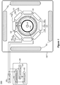
- FIG. 1 is a block diagram of a system 100 for combined Positron-Emission Tomography (PET) and Magnetic Resonance Imaging (MRI), according to some embodiments of the invention.
- PET Positron-Emission Tomography
- MRI Magnetic Resonance Imaging
- System 100 can include at least one magnet 102 to generate a magnetic field within a predetermined measurement volume 104 .
- magnets 102 include at least one of permanent magnets, superconductive magnets or a combination thereof.
- System 100 can include a housing 106 to at least partly surround magnets 102 .
- Housing 106 can, for example, substantially eliminate a magnetic fringe field generated by magnets 102 outside housing 106 .
- System 100 can include a radio frequency (RF) coil 110 (e.g., solenoid) having a RF coil bore 111 , a RF coil diameter and a RF coil length.
- the RF coil diameter and/or the RF coil length can have values that allow RF coil 110 to accommodate a subject 90 (e.g., a mouse), or at least a portion of subject 90 , within RF coil bore 111 .
- RF coil bore 111 can at least partly overlap with predetermined measurement volume 104 .
- the RF coil diameter ranges between, for example 30-40 mm and/or the RF coil length ranges between, for example 40-55 mm.
- RF coil 110 can generate an electromagnetic field within RF coil bore 111 to excite a magnetic moment of nuclei within subject 90 (or within a predetermined portion of subject 90 ).
- RF coil 110 can be arranged to receive signals generated due to relaxation of the excited nuclei thereof.
- system 100 includes two (or more) RF coils, for example a first RF coil and a second RF coil (not shown), wherein first RF coil generates the electromagnetic field to excite nuclei within subject 90 and second RF coil receives the signals generated due to relaxation of the nuclei thereof.
- System 100 can include a Positron-Emission Tomography (PET) detectors array 120 having a PET detectors array diameter and a PET detectors array length.
- PET detectors array 120 can surround RF coil 110 .
- PET detectors array 120 can include a plurality of detectors (e.g., detectors 120a , 120b , 120c , 120d , 120e , 120f , 120g , 120h , as shown in Figure 1 ) to detect gamma rays emitted by positron-emitting radionuclides within subject 90 (or within a predetermined portion of subject 90 ).
- positron-emitting radionuclides are injected into a subject (or the subject can swallow or inhale the radionuclides thereof) prior to taking PET images.
- RF coil 110 and PET detectors array 120 have a substantially annular shape and/or can be positioned concentrically (e.g., as shown in Figure 1 ). In some embodiments, RF coil 110 and PET detectors array 120 are positioned at a predetermined radial distance with respect to each other (not shown). The position of RF coil 110 and the position of PET detectors array 120 within system 100 can be determined based on, for example, a desired application and/or desired dimensions of system 100 .
- System 100 can include a RF shield 130 having a RF shield diameter and a RF shield length.
- RF shield 130 can surround RF coil 110 .
- RF shield 130 can be positioned between RF coil 110 and PET detectors array 120 (e.g., as shown in Figure 1 ).
- RF coil 110, PET detectors array 120 and RF shield 130 are positioned to provide a first space 131 between RF coil 110 and RF shield 130 and/or to provide a second space 132 between PET 120 and RF shield 130 (e.g., as shown in Figure 1 ).
- RF shield 130 can include a conductive material (e.g., copper, aluminum, and/or any other material capable of providing shielding).
- RF shield 130 is arranged to form a Faraday cage to provide a RF shielding (and/or electromagnetic shielding) of system 100 (e.g., as discussed below with respect to Figure 2D and Figure 2G ).
- the RF shielding includes, for example, preventing (or substantially preventing) a RF radiation generated by RF coil 110 from exiting RF coil bore 111 and preventing a RF radiation generated by PET detectors array 120 from entering RF coil bore 111 , to thereby prevent interference between RF coil 110 and PET detectors array 120.
- the RF shielding includes preventing (or substantially preventing) RF radiation (e.g., generated by RF coil 110) from exiting predetermined measurement volume 104 and/or preventing external RF radiation from entering predetermined measurement volume 104 .
- first space 131 between RF coil 110 and RF shield 130 and/or second space 132 between PET detectors array 120 and RF shield 130 are determined to, for example, eliminate (or substantially eliminate) the RF shieling effect on the electromagnetic field generated by RF coil 110 within RF coil bore 111 , while providing the RF shielding of PET detectors array 120 and/or of system 100 (e.g., as described above).
- first space 131 can be larger as compared to second space 132.
- System 100 can include a control unit 150 in communication with RF coil 110 and with PET detectors array 120 .
- Control unit 150 can operate RF coil 110 and PET detectors array 120 according to a predetermined operation pattern (e.g., direct the RF coil and/or PET detector array to generate electromagnetic, magnetic fields or any combination thereof having specific intensities, directions, in accordance with operations parameters of MRI and PET as is known in the art).
- the predetermined operation pattern includes directing simultaneous operation of RF coil unit 110 , and thus MRI imaging, and of PET detectors array 120 , and thus PET imaging.
- RF coil 110 can generate electromagnetic field within RF coil bore 111 and, at the same time, PET detectors array 120 can detect gamma rays emitted from subject 90 .
- the system can perform simultaneous PET and MRI imaging, in some embodiments, it may be desirable to operate the system in an exclusively PET or MRI mode.
- the predetermined operation pattern can include directions for separate operation of MRI device 80 and of PET detectors array 120 .
- RF coil 110 can generate electromagnetic field within RF coil bore 111 and, after a predetermined time delay, PET detectors array 120 can detect gamma rays emitted from subject 90, or vice versa.
- PET detectors array 120 is positioned such that the electromagnetic radiation produced by RF coil 110 absent RF shield 130 impinges upon PET detectors of PET detectors array 120 . If the PET detectors of PET detectors array 120 are subject to the electromagnetic radiation from RF coil 110 , the measurements of the PET detectors of PET detectors array 120 can be erroneous and/or completely unreadable. As described above, RF shield 130 positioned between RF coil 110 and PET detectors array 120 can prevent the electromagnetic radiation from coil 110 from ruining PET detectors array 120 measurements because, for example, PET detectors array 120 is shielded. In this manner, simultaneous PET imaging and MRI imaging can occur, without, for example, any one of RF coil 110 , PET detectors array 120 and/or subject 90 being moved during an imaging procedure.
- System 100 can include an analysis unit 160 .
- Analysis unit 160 can include a MRI processing unit 162 .
- MRI processing unit 162 can receive MRI data (e.g., signals received by RF coil 110 ) and generate, based on the MRI data, one or more MRI images of subject 90 (or at least a portion of subject 90 ).
- the MRI images include at least one of a set of temporary sequential MRI images of subject 90 , a set of spatial MRI images of subject 90 or any combination thereof.
- PET processing unit 164 can receive PET data (e.g., received by PET detectors array 120 ) and generate, based on the PET data, one or more PET images of subject 90 (or at least a portion of subject 90 ).
- the PET images include at least one of a set of temporary sequential PET images of subject 90 , a set of spatial PET images of subject 90 or any combination thereof.
- Analysis unit 160 can include a processing unit 166 .
- Processing unit 166 can receive the MRI images (e.g., from MRI processing unit 162 ) and the PET images (e.g., from PET processing unit 164 ).
- the MRI images and/or the PET images are generated external to analysis unit 160
- analysis unit 160 can be adapted to receive the externally generated MRI images and PET images.
- Processing unit 166 can combine at least one of the MRI images with at least one of the PET images to thereby generate at least one combined PET-MRI image.
- the combining includes any one of registering, superimposing and/or fusing the MRI images and the PET images.
- the combined images include spatially registered and/or temporally registered MRI images and PET images of subject 90 (or at least a portion of subject 90) acquired under identical physiological conditions.
- An example of combined PET-MRI image (e.g., generated by system 100) is described below with respect to Figure 3 .
- system 100 includes other detectors (not shown) that are not influenced by RF shielding generated by RF shield 130 (e.g., as described above).
- system 100 can include optical detectors positioned external to RF coil bore 111 (not shown).
- RF shield 130 can include openings at predetermined locations along RF shield 130 , to, for example, enable detection of photons emitted from subject 90 by the optical detectors thereof.
- Analysis unit 160 can be further arranged to generate at least one optical image (e.g., based on optical data received from the optical detectors) and further to combine the at least one optical image with the at least one MRI image and/or with the at least one PET image (e.g., as described above).
- FIG. 2A is a schematic illustration of a system for combined Positron-Emission Tomography (PET) and Magnetic Resonance Imaging (MRI), such as system 100, according to some embodiments of the invention.
- PET Positron-Emission Tomography
- MRI Magnetic Resonance Imaging
- System 100 can include a RF coil structure 160 and/or PET structure 170 (e.g., as shown in Figure 2A ).
- RF coil structure 160 and/or PET structure 170 can be used to, for example, insert RF coil 110 accommodating subject 90 and PET detectors array 120 into measurement volume 104 (e.g., within housing 106 ) of system 100 (e.g., as described below with respect to Figures 2B-2C ).
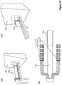
- FIG. 2B shows schematic illustrations of a RF coil structure, such as RF coil structure 160 , of a system for combined Positron-Emission Tomography (PET) and Magnetic Resonance Imaging (MRI), such as system 100 , according to some embodiments of the invention.
- PET Positron-Emission Tomography
- MRI Magnetic Resonance Imaging
- Illustrations 160a and 160b in Figure 2B show a RF coil structure 160 positioned external to housing 160 (e.g., in a non-operating position) and inside housing 106 (e.g., in an operating position), respectively.
- Illustration 160c in Figure 2B shows a cradle 162 of RF coil structure 160 accommodating subject 90 .
- RF coil structure 160 can include, at RF coil structure's distal end 161a , a cradle 162 .
- Cradle 162 can receive and accommodate a subject 90 , for example a mouse.
- RF coil 110 is mounted on, or embedded within, a RF coil support 115 (e.g., as shown in Figure 2B ).
- RF coil support 115 can be mounted on cradle 162 such that RF coil 110 surrounds cradle 162 .
- RF coil support 110 can be thread onto cradle 162 such that RF coil bore 111 accommodates both subject 90 and cradle 162 .
- RF coil structure 160 can be inserted into housing 106 via, for example, an opening 106a on a front face 106b of housing 106 .
- a RF coil structure's 160 length and/or cradle's 162 length can be determined to position cradle 162 , RF coil 110 and subject 90 within predetermined measurement volume 104 within housing 106 .
- RF coil structure 160 can include a handle 164 affixed to a RF coil structure's proximal end 161b to, for example, insert and/or remove RF coil structure 160 into/from housing 106 .
- RF coil structure 160 can be arranged to route RF coil's 110 wiring and/or medical tubing connected to subject 90 external to housing 106 , e.g., through an interior 165 of RF coil structure 160 (e.g., as shown in Figure 2G ), while preventing (or substantially preventing) an external RF radiation from entering predetermined measurement volume 104 and/or preventing (or substantially preventing) RF radiation from exiting predetermined measurement volume 104 .
- FIG. 2C shows schematic illustrations of a PET structure, such as PET structure 170 , of a system for combined Positron-Emission Tomography (PET) and Magnetic Resonance Imaging (MRI), such as system 100 , according to some embodiments of the invention.
- PET Positron-Emission Tomography
- MRI Magnetic Resonance Imaging
- Illustrations 170a and 170b in Figure 2C show a PET structure 170 positioned partly external to housing 106 (e.g., in a non-operating position) and inside housing 106 (e.g., in an operating position), respectively.
- Illustration 170c in Figure 2C shows PET detectors array 120 and PET structure 170 external to housing 106 .
- PET detectors array 120 can include one or more PET detectors array parts that can be mounted on a distal portion 171a of PET structure 170 .
- PET detectors array 120 can include a first PET detectors array part 120-1 and a second PET detectors array part 120-2 (e.g., as shown in Figure 2C ).
- PET structure 170 can be inserted into housing 106 via, for example, an opening 106d on a back face 106c of housing 106.
- a PET structure's 170 length can be determined to position PET detectors array 120 mounted on PET structure's distal portion 171a within predetermined measurement volume 104 to thereby surround RF coil 110 and RF shield 130 (e.g., as described above with respect to Figure 1 ).
- PET structure 170 can be arranged to route PET detectors array's 120 wiring external to housing 106 (e.g., through an interior of PET structure 170 ) while preventing (or substantially preventing) an external RF radiation from entering predetermined measurement volume 104 and/or preventing (or substantially preventing) RF radiation from exiting predetermined measurement volume 104.
- FIG. 2D shows schematic illustrations of a radiofrequency (RF) shield, such as RF shield 130, of a system for combined Positron-Emission Tomography (PET) and Magnetic Resonance Imaging (MRI), such as system 100, including two RF shield parts 130-1 , 130-2 , according to some embodiments of the invention.
- RF radiofrequency
- Illustration 130a in Figure 2D shows a first RF shield part 130-1 and a second RF shield part 130-2 .
- Illustration 130b in Figure 2D shows a second RF shield part 130-2 external to housing 106.
- Illustration 130c in Figure 2D shows first RF shield part 130-1 and second RF shield part 130-2 within housing 106.
- RF shield 130 includes two RF shield parts, for example, a first RF shield part 130-1 and a second RF shield part 130-2 (e.g., as shown in Figure 2D ).
- first RF shield part 130-1 and second RF shield part 130-1 can include conductive material (e.g., copper).
- conductive material e.g., copper
- each of first RF shield part 130-1 and/or second RF shield part 130-2 can be a copper cylinder and/or can be a substantially annular sleeve that can include a copper mesh.
- RF structure 160 is arranged to electrically connect, upon insertion into housing 106, to first RF shield part 130-1 and to second RF shield part 130-2 (e.g., as shown below in Figure 2G ) to form a Faraday cage to thereby provide RF shielding of system 100.
- the RF shielding can include, for example, preventing (or substantially preventing) RF radiation (e.g., generated by RF coil 110 ) from exiting predetermined measurement volume 104 and preventing (or substantially preventing) external RF radiation from entering predetermined measurement volume 104 and/or preventing (or substantially preventing) interference between RF coil 110 and PET detectors 120 (e.g., as described above with respect to Figure 1 ).
- FIG. 2E is a schematic illustrations of a radiofrequency (RF) sleeve 135 of a system for combined Positron-Emission Tomography (PET) and Magnetic Resonance Imaging (MRI), such as system 100 , according to some embodiments of the invention.
- RF radiofrequency
- System 100 can include a RF sleeve 135 .
- RF sleeve 135 can include a metal mesh 136 (e.g., made of conductive material, such as copper). Metal mesh 136 can be embedded within, for example, fabric material 137 .
- RF sleeve 135 envelopes cradle 162 of RF structure 160 accommodating RF coil 110 and subject 90 .
- RF sleeve 135 can be electrically connected to RF structure 160 to form a Faraday cage to thereby provide additional RF shielding (e.g., additional to RF shielding provided by RF shield 130) of RF coil 110 and PET detectors 120 (e.g., as described above with respect to Figure 1 ) .
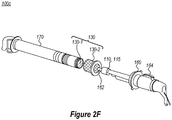
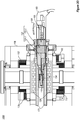
- Figure 2F and Figure 2G are schematic illustrations of a RF shield 130 , RF coil structure 160 and PET structure 170 in a disassembled state external to housing 106 and in an assembled state within housing 106 of a system for combined Positron-Emission Tomography (PET) and Magnetic Resonance Imaging (MRI), such as system 100 , respectively, according to some embodiments of the invention.
- Illustration 100c in Figure 2F shows a perspective view and illustration 100d in Figure 2G shows a cross-sectional view.
- Positioning ofRF coil structure 160 into operating position can locate cradle 162 and RF coil 110 (e.g., surrounding subject 90 ) within predetermined measurement volume 104 .
- Positioning of PET structure 170 into operating position can locate PET detectors 120 to surround RF coil 110 and RF shield 130 (e.g., first RF shield part 130-1 , as shown in Figure 2G ) along predetermined measurement volume 104.
- RF coil structure 160 , PET structure 170 , first RF shield part 130-1 and/or second RF shield part 130-2 can be electrically connected (e.g., as shown in Figure 2G ) to provide the Faraday cage (e.g., as described above with respect to Figure 2D ).
- the Faraday cage can provide RF shielding of system 100 to thereby prevent (or substantially prevent) RF radiation (e.g., generated by RF coil 110 ) from exiting predetermined measurement volume 104 and prevent external RF radiation from entering predetermined measurement volume 104 and/or prevent (or substantially prevent) interference between RF coil 110 and PET detectors 120 (e.g., as described above with respect to Figure 1 and Figure 2D ).
- RF radiation e.g., generated by RF coil 110
- PET detectors 120 e.g., as described above with respect to Figure 1 and Figure 2D .
- elements of system 100 are scaled in size for accommodation of an adult human, a portion of the adult human (e.g., a head), a human infant, a portion of the human infant (e.g., a head) and/or laboratory animals (e.g., rats, pigs, etc.).
- a portion of the adult human e.g., a head
- a human infant e.g., a head
- laboratory animals e.g., rats, pigs, etc.
- FIG. 3 is an example of a simultaneously acquired MRI image 210 and PET image 212 , and a combined PET-MRI image 214 of a subject 90 , such as mouse, generated by a system for combined Positron-Emission Tomography (PET) and Magnetic Resonance Imaging (MRI), such as system 100, according to some embodiments of the invention.
- PET Positron-Emission Tomography
- MRI Magnetic Resonance Imaging
- Combining of simultaneously acquired MRI images 210 and PET images 212 into combined PET-MRI image 214 allows to determine structural data (e.g., from MRI images) and functional (and/or molecular) data (e.g., from PET images 214 ) relating to subject 90 , wherein the structural and the functional data is spatially and temporally registered and acquired under identical physiological conditions.
- Some embodiments of the present invention can include a device for combined PET-MRI, which can be operative in a MRI device.
- the MRI device e.g., that can utilize superconductive magnets, permanent magnets and/or a combination thereof to generate a magnetic field
- the MRI device can be retrofitted to receive the device and to operate in combination with the device.
- the device can include a RF coil having a RF coil bore that at least partly overlaps with a predetermined measurement volume of the MRI device and having a diameter to accommodate at least a portion of a subject (e.g., RF coil 110 , as described above with respect to Figure 1 and Figure 2B ).
- the RF coil can generate an electromagnetic field within the RF coil bore to excite nuclei within the at least portion of the subject and to receive signals emitted from the at least portion of the subject when the electromagnetic field is removed and the excited nuclei relax.
- the device can include a PET detectors array surrounding the RF coil and to detect gamma rays emitted by positron-emitting (PE) radionuclides within the subject (e.g., PET detectors array 120, as described above with respect to Figure 1 and Figure 2C ).
- PET detectors array 120 e.g., PET detectors array 120, as described above with respect to Figure 1 and Figure 2C .
- the device can include a RF shield surrounding the RF coil and positioned between the RF coil and the PET detectors array (e.g., RF shield 130 , as described above with respect to Figure 1 , Figures 2D-2E and Figure 2G ).
- a RF shield surrounding the RF coil and positioned between the RF coil and the PET detectors array (e.g., RF shield 130 , as described above with respect to Figure 1 , Figures 2D-2E and Figure 2G ).
- the device includes features from different embodiments of system 100 described above with respect to Figure 1 and Figures 2A -2G .
- the device can include a RF coil structure (e.g., RF coil structure 160 , as described above with respect to Figure 2B ) and a PET structure (e.g., PET structure 170 , as described above with respect to Figure 2C ) to thereby enable insertion of the device within the predetermined measurement volume of the MRI device; and/or the device can include an analysis unit (e.g., analysis unit 160 , as described above with respect to Figure 1 ), to generate combined PET MRI images (e.g., as described above with respect to Figure 1 and Figure 3 ).
- RF coil structure e.g., RF coil structure 160 , as described above with respect to Figure 2B
- a PET structure e.g., PET structure 170 , as described above with respect to Figure 2C
- an analysis unit e.g., analysis unit 160 , as described above with respect to Figure 1
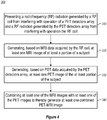
- FIG. 4 is a flowchart of a method 300 of generating at least one combined magnetic resonance imaging (MRI) image and Positron-Emission Tomography (PET) image, according to some embodiments of the invention.
- Method 300 can be implemented by system 100 , which may be configured to implement method 300 .
- Method 300 can include preventing 310 a radio frequency (RF) radiation generated by a RF coil from interfering with operation of a PET detectors array and a RF radiation generated by the PET detectors array from interfering with operation the RF coil.
- RF radio frequency
- an RF shield can be positioned between the RF coil and the PET detectors array (e.g., as described above with respect to Figure 1 , Figures 2D-2E and Figure 2G ).
- Method 300 can include generating 320 (e.g., by analysis unit 160, as described above with respect to Figure 1 ), based on MRI data acquired by the RF coil, at least one MRI image (e.g., MRI image 210 , as described above with respect to Figure 3 ) of at least portion of a subject.
- generating 320 e.g., by analysis unit 160, as described above with respect to Figure 1
- at least one MRI image e.g., MRI image 210 , as described above with respect to Figure 3
- Method 300 can include generating 330 (e.g., by analysis unit 160 , as described above with respect to Figure 1 ), based on PET data acquired by the PET detectors array, at least one PET image (e.g., PET image 212, as described above with respect to Figure 3 ) of the at least portion of the subject.
- generating 330 e.g., by analysis unit 160 , as described above with respect to Figure 1
- at least one PET image e.g., PET image 212, as described above with respect to Figure 3
- Method 300 can include combining 340 (e.g., by analysis unit 160 , as described above with respect to Figure 1 ) at least one of the MRI images with at least one of the PET images to thereby generate at least one combined PET-MRI image (e.g., combined PET-MRI image 214 , as described above with respect to Figure 3 ).
- combining 340 e.g., by analysis unit 160 , as described above with respect to Figure 1
- at least one of the MRI images with at least one of the PET images to thereby generate at least one combined PET-MRI image (e.g., combined PET-MRI image 214 , as described above with respect to Figure 3 ).
- method 300 includes operating the RF coil and the PET detectors array simultaneously (e.g., at the same time) or separately (e.g., at a predetermined time-delay with respect to each other) without any one of the RF coil, the PET detectors array or the subject being moved (e.g., as described above with respect to Figure 1 ).
- the combining includes at least one of registering, superimposing, fusing or any combination thereof of at least one of the MRI images and at least one of the PET images.
- the combined PET-MRI images include spatially registered and/or temporally registered MRI images and PET images of the subject (or at least a portion of the subject) acquired under identical physiological conditions (e.g., as described above with respect to Figure 1 ).
- One advantage of some embodiments of the present invention is that they allow simultaneous acquisition of MRI data of a subject, e.g., by a RF coil surrounding the subject, and PET data of the subject, e.g., by a PET detectors array surrounding the RF coil, without moving any one of the RF coils, the PET detectors array or the subject during an imaging procedure.
- Acquiring the MRI data and the PET data simultaneously can be achieved due to a RF shield surrounding the RF coil and positioned between the RF coil and the PET detectors array, which prevents an interference between the RF coil and the PET detectors array thereof.
- the simultaneous acquisition of the MRI data and the PET data allows determining a spatially and temporally registered structural, functional and/or molecular data acquired under identical physiological conditions.
- an embodiment is an example or implementation of the invention.
- the various appearances of "one embodiment”, “an embodiment”, “certain embodiments” or “some embodiments” do not necessarily all refer to the same embodiments.
- various features of the invention can be described in the context of a single embodiment, the features can also be provided separately or in any suitable combination.
- the invention can also be implemented in a single embodiment.
- Certain embodiments of the invention can include features from different embodiments disclosed above, and certain embodiments can incorporate elements from other embodiments disclosed above.
- the disclosure of elements of the invention in the context of a specific embodiment is not to be taken as limiting their use in the specific embodiment alone.
- the invention can be carried out or practiced in various ways and that the invention can be implemented in certain embodiments other than the ones outlined in the description above.
Landscapes
- Health & Medical Sciences (AREA)
- Physics & Mathematics (AREA)
- Life Sciences & Earth Sciences (AREA)
- Engineering & Computer Science (AREA)
- Nuclear Medicine, Radiotherapy & Molecular Imaging (AREA)
- High Energy & Nuclear Physics (AREA)
- Radiology & Medical Imaging (AREA)
- General Health & Medical Sciences (AREA)
- General Physics & Mathematics (AREA)
- Medical Informatics (AREA)
- Molecular Biology (AREA)
- Condensed Matter Physics & Semiconductors (AREA)
- Biophysics (AREA)
- Biomedical Technology (AREA)
- Animal Behavior & Ethology (AREA)
- Heart & Thoracic Surgery (AREA)
- Public Health (AREA)
- Veterinary Medicine (AREA)
- Pathology (AREA)
- Surgery (AREA)
- Pulmonology (AREA)
- Theoretical Computer Science (AREA)
- Optics & Photonics (AREA)
- Spectroscopy & Molecular Physics (AREA)
- Epidemiology (AREA)
- Nuclear Medicine (AREA)
Applications Claiming Priority (1)
| Application Number | Priority Date | Filing Date | Title |
|---|---|---|---|
| US201662393059P | 2016-09-11 | 2016-09-11 |
Publications (1)
| Publication Number | Publication Date |
|---|---|
| EP3293534A1 true EP3293534A1 (de) | 2018-03-14 |
Family
ID=59846513
Family Applications (1)
| Application Number | Title | Priority Date | Filing Date |
|---|---|---|---|
| EP17190444.4A Withdrawn EP3293534A1 (de) | 2016-09-11 | 2017-09-11 | Kombination von magnetresonanztomographie (mrt) und positronen-emissions-tomographie (pet) |
Country Status (2)
| Country | Link |
|---|---|
| US (1) | US20180074144A1 (de) |
| EP (1) | EP3293534A1 (de) |
Families Citing this family (10)
| Publication number | Priority date | Publication date | Assignee | Title |
|---|---|---|---|---|
| AU2017203411A1 (en) * | 2016-06-01 | 2017-12-21 | Strata Products Worldwide, Llc | Method and apparatus for identifying when an idividual is in proximity to an object |
| US10942235B2 (en) * | 2018-03-28 | 2021-03-09 | National Institutes For Quantum And Radiological Science And Technology | Microstrip transmission line array RF coil, RF shield configuration and integrated apparatus of RF coil and radiation imaging device |
| WO2020057654A1 (en) * | 2018-09-21 | 2020-03-26 | Shanghai United Imaging Healthcare Co., Ltd. | Systems for imaging |
| US11090012B2 (en) * | 2019-01-29 | 2021-08-17 | Shanghai United Imaging Healthcare Co., Ltd. | Positron emission tomography-magnetic resonance imaging apparatus |
| WO2020172673A1 (en) * | 2019-02-22 | 2020-08-27 | Promaxo, Inc. | Systems and methods for performing magnetic resonance imaging |
| US11686797B2 (en) * | 2019-12-12 | 2023-06-27 | GE Precision Healthcare LLC | Method and system for motion compensation in hybrid PET-MR imaging |
| EP3882648B1 (de) * | 2020-03-18 | 2024-09-25 | Siemens Healthineers AG | Hf-spulenvorrichtung für eine mr- oder mr-pet-bildgebungsmodalität und verfahren zur bestimmung der position und/oder ausrichtung und/oder form einer solchen hf-spulenvorrichtung |
| US11402451B2 (en) * | 2020-09-24 | 2022-08-02 | Siemens Medical Solutions Usa, Inc. | Timing signal distribution to pet imaging components via optical path |
| US11707202B2 (en) | 2020-09-24 | 2023-07-25 | Electronics And Telecommunications Research Institute | Apparatus for generating field-free region, apparatus and method for nano magnetic particle image |
| CN118806306A (zh) * | 2024-08-20 | 2024-10-22 | 深圳湾实验室 | 成像系统及其成像方法 |
Citations (6)
| Publication number | Priority date | Publication date | Assignee | Title |
|---|---|---|---|---|
| WO2008084438A2 (en) * | 2007-01-11 | 2008-07-17 | Koninklijke Philips Electronics N.V. | Pet/mr scanners for simultaneous pet and mr imaging |
| US20080267478A1 (en) * | 2007-04-24 | 2008-10-30 | Michael Eberler | Device consisting of a combination of a magnetic resonance tomograph and a positron emission tomograph |
| US20120223715A1 (en) * | 2010-09-02 | 2012-09-06 | Hyunwook Park | Pet-mri convergence system |
| US20130193974A1 (en) * | 2012-02-01 | 2013-08-01 | General Electric Company | Radio frequency (rf) body coil assembly for dual-modality imaging |
| US20130234710A1 (en) * | 2010-11-01 | 2013-09-12 | Toshiba Medical Systems Corporation | Pet-mri apparatus |
| US20130293232A1 (en) * | 2012-05-02 | 2013-11-07 | Eddy Benjamin Boskamp | Structured rf coil assembly for mri scanner |
Family Cites Families (1)
| Publication number | Priority date | Publication date | Assignee | Title |
|---|---|---|---|---|
| US7667457B2 (en) * | 2006-12-22 | 2010-02-23 | General Electric Co. | System and apparatus for detecting gamma rays in a PET/MRI scanner |
-
2017
- 2017-09-11 EP EP17190444.4A patent/EP3293534A1/de not_active Withdrawn
- 2017-09-11 US US15/700,839 patent/US20180074144A1/en not_active Abandoned
Patent Citations (6)
| Publication number | Priority date | Publication date | Assignee | Title |
|---|---|---|---|---|
| WO2008084438A2 (en) * | 2007-01-11 | 2008-07-17 | Koninklijke Philips Electronics N.V. | Pet/mr scanners for simultaneous pet and mr imaging |
| US20080267478A1 (en) * | 2007-04-24 | 2008-10-30 | Michael Eberler | Device consisting of a combination of a magnetic resonance tomograph and a positron emission tomograph |
| US20120223715A1 (en) * | 2010-09-02 | 2012-09-06 | Hyunwook Park | Pet-mri convergence system |
| US20130234710A1 (en) * | 2010-11-01 | 2013-09-12 | Toshiba Medical Systems Corporation | Pet-mri apparatus |
| US20130193974A1 (en) * | 2012-02-01 | 2013-08-01 | General Electric Company | Radio frequency (rf) body coil assembly for dual-modality imaging |
| US20130293232A1 (en) * | 2012-05-02 | 2013-11-07 | Eddy Benjamin Boskamp | Structured rf coil assembly for mri scanner |
Non-Patent Citations (1)
| Title |
|---|
| WILLIAM B HANDLER ET AL: "Simulation of scattering and attenuation of 511 keV photons in a combined PET/field-cycled MRI system; Simulation of scattering and attenuation of 511 keV photons", PHYSICS IN MEDICINE AND BIOLOGY, INSTITUTE OF PHYSICS PUBLISHING, BRISTOL GB, vol. 51, no. 10, 21 May 2006 (2006-05-21), pages 2479 - 2491, XP020095754, ISSN: 0031-9155, DOI: 10.1088/0031-9155/51/10/008 * |
Also Published As
| Publication number | Publication date |
|---|---|
| US20180074144A1 (en) | 2018-03-15 |
Similar Documents
| Publication | Publication Date | Title |
|---|---|---|
| EP3293534A1 (de) | Kombination von magnetresonanztomographie (mrt) und positronen-emissions-tomographie (pet) | |
| JP3176221U (ja) | 三次元解剖学的および機能的画像化のための画像化デバイスおよびその方法 | |
| KR100842682B1 (ko) | Pet - mri 하이브리드 시스템 | |
| US9261574B2 (en) | Structured RF coil assembly for MRI scanner | |
| CN104823068B (zh) | 减少在包括mri系统和非mr成像系统的组合系统中的干扰 | |
| JP5593330B2 (ja) | Petまたはspectおよびmrの同時画像を形成するためのコンパクトでハイブリッドで統合的なガンマ/rfシステム | |
| CN101526595B (zh) | 具有pet单元的磁共振设备 | |
| US20090206836A1 (en) | Detection unit including an RF transceiver system and a pet detector | |
| US10288702B2 (en) | System for simultaneous PET/MR imaging | |
| US8816686B2 (en) | PET-MRI convergence system | |
| CN105378501A (zh) | 用于多模态成像的表面静止阵列线圈结构 | |
| US20160209486A1 (en) | Motion sensor | |
| US20120165654A1 (en) | Means and method for performing hyperpolarizing gas imaging | |
| KR100930608B1 (ko) | 융합 영상 획득장치 및 그 구동방법 | |
| KR101242500B1 (ko) | Pet-mri 융합시스템 | |
| CN105044633B (zh) | 膝部线圈 | |
| CN104138261B (zh) | 包括磁共振成像单元和pet单元的医学成像系统 | |
| US20140221817A1 (en) | Method for generating attenuation correction for a combined magnetic resonance-positron emission tomography device | |
| Sato‐Akaba et al. | Three‐dimensional whole‐body imaging of the bioreduction and clearance of nitroxide probes in the thoracic and abdominal regions of mice using a compact and mobile electron paramagnetic resonance imager | |
| JP7523144B2 (ja) | 放射線画像化ユニット及び放射線検出器モジュール | |
| Maramraju et al. | An MR compatible PET scanner based on RatCAP for small animal imaging at 9.4 T | |
| KR20180039435A (ko) | 소동물용 다핵종(수소-탄소) 융합 실린더-레일형 mri 코일 |
Legal Events
| Date | Code | Title | Description |
|---|---|---|---|
| PUAI | Public reference made under article 153(3) epc to a published international application that has entered the european phase |
Free format text: ORIGINAL CODE: 0009012 |
|
| STAA | Information on the status of an ep patent application or granted ep patent |
Free format text: STATUS: THE APPLICATION HAS BEEN PUBLISHED |
|
| AK | Designated contracting states |
Kind code of ref document: A1 Designated state(s): AL AT BE BG CH CY CZ DE DK EE ES FI FR GB GR HR HU IE IS IT LI LT LU LV MC MK MT NL NO PL PT RO RS SE SI SK SM TR |
|
| AX | Request for extension of the european patent |
Extension state: BA ME |
|
| STAA | Information on the status of an ep patent application or granted ep patent |
Free format text: STATUS: REQUEST FOR EXAMINATION WAS MADE |
|
| 17P | Request for examination filed |
Effective date: 20180913 |
|
| RBV | Designated contracting states (corrected) |
Designated state(s): AL AT BE BG CH CY CZ DE DK EE ES FI FR GB GR HR HU IE IS IT LI LT LU LV MC MK MT NL NO PL PT RO RS SE SI SK SM TR |
|
| STAA | Information on the status of an ep patent application or granted ep patent |
Free format text: STATUS: EXAMINATION IS IN PROGRESS |
|
| 17Q | First examination report despatched |
Effective date: 20210209 |
|
| STAA | Information on the status of an ep patent application or granted ep patent |
Free format text: STATUS: THE APPLICATION HAS BEEN WITHDRAWN |
|
| 18W | Application withdrawn |
Effective date: 20210609 |