EP3293557A1 - Optique et système optique - Google Patents
Optique et système optique Download PDFInfo
- Publication number
- EP3293557A1 EP3293557A1 EP17187996.8A EP17187996A EP3293557A1 EP 3293557 A1 EP3293557 A1 EP 3293557A1 EP 17187996 A EP17187996 A EP 17187996A EP 3293557 A1 EP3293557 A1 EP 3293557A1
- Authority
- EP
- European Patent Office
- Prior art keywords
- optics
- optical system
- coupling surfaces
- coupling
- main
- Prior art date
- Legal status (The legal status is an assumption and is not a legal conclusion. Google has not performed a legal analysis and makes no representation as to the accuracy of the status listed.)
- Granted
Links
Images

Classifications
-
- G—PHYSICS
- G02—OPTICS
- G02B—OPTICAL ELEMENTS, SYSTEMS OR APPARATUS
- G02B3/00—Simple or compound lenses
- G02B3/0006—Arrays
- G02B3/0037—Arrays characterized by the distribution or form of lenses
- G02B3/0043—Inhomogeneous or irregular arrays, e.g. varying shape, size, height
-
- F—MECHANICAL ENGINEERING; LIGHTING; HEATING; WEAPONS; BLASTING
- F21—LIGHTING
- F21S—NON-PORTABLE LIGHTING DEVICES; SYSTEMS THEREOF; VEHICLE LIGHTING DEVICES SPECIALLY ADAPTED FOR VEHICLE EXTERIORS
- F21S41/00—Illuminating devices specially adapted for vehicle exteriors, e.g. headlamps
- F21S41/10—Illuminating devices specially adapted for vehicle exteriors, e.g. headlamps characterised by the light source
- F21S41/14—Illuminating devices specially adapted for vehicle exteriors, e.g. headlamps characterised by the light source characterised by the type of light source
- F21S41/141—Light emitting diodes [LED]
- F21S41/143—Light emitting diodes [LED] the main emission direction of the LED being parallel to the optical axis of the illuminating device
-
- F—MECHANICAL ENGINEERING; LIGHTING; HEATING; WEAPONS; BLASTING
- F21—LIGHTING
- F21S—NON-PORTABLE LIGHTING DEVICES; SYSTEMS THEREOF; VEHICLE LIGHTING DEVICES SPECIALLY ADAPTED FOR VEHICLE EXTERIORS
- F21S41/00—Illuminating devices specially adapted for vehicle exteriors, e.g. headlamps
- F21S41/10—Illuminating devices specially adapted for vehicle exteriors, e.g. headlamps characterised by the light source
- F21S41/14—Illuminating devices specially adapted for vehicle exteriors, e.g. headlamps characterised by the light source characterised by the type of light source
- F21S41/141—Light emitting diodes [LED]
- F21S41/151—Light emitting diodes [LED] arranged in one or more lines
- F21S41/153—Light emitting diodes [LED] arranged in one or more lines arranged in a matrix
-
- F—MECHANICAL ENGINEERING; LIGHTING; HEATING; WEAPONS; BLASTING
- F21—LIGHTING
- F21S—NON-PORTABLE LIGHTING DEVICES; SYSTEMS THEREOF; VEHICLE LIGHTING DEVICES SPECIALLY ADAPTED FOR VEHICLE EXTERIORS
- F21S41/00—Illuminating devices specially adapted for vehicle exteriors, e.g. headlamps
- F21S41/20—Illuminating devices specially adapted for vehicle exteriors, e.g. headlamps characterised by refractors, transparent cover plates, light guides or filters
- F21S41/24—Light guides
-
- F—MECHANICAL ENGINEERING; LIGHTING; HEATING; WEAPONS; BLASTING
- F21—LIGHTING
- F21S—NON-PORTABLE LIGHTING DEVICES; SYSTEMS THEREOF; VEHICLE LIGHTING DEVICES SPECIALLY ADAPTED FOR VEHICLE EXTERIORS
- F21S41/00—Illuminating devices specially adapted for vehicle exteriors, e.g. headlamps
- F21S41/20—Illuminating devices specially adapted for vehicle exteriors, e.g. headlamps characterised by refractors, transparent cover plates, light guides or filters
- F21S41/25—Projection lenses
- F21S41/255—Lenses with a front view of circular or truncated circular outline
-
- F—MECHANICAL ENGINEERING; LIGHTING; HEATING; WEAPONS; BLASTING
- F21—LIGHTING
- F21S—NON-PORTABLE LIGHTING DEVICES; SYSTEMS THEREOF; VEHICLE LIGHTING DEVICES SPECIALLY ADAPTED FOR VEHICLE EXTERIORS
- F21S41/00—Illuminating devices specially adapted for vehicle exteriors, e.g. headlamps
- F21S41/20—Illuminating devices specially adapted for vehicle exteriors, e.g. headlamps characterised by refractors, transparent cover plates, light guides or filters
- F21S41/285—Refractors, transparent cover plates, light guides or filters not provided in groups F21S41/24 - F21S41/2805
-
- F—MECHANICAL ENGINEERING; LIGHTING; HEATING; WEAPONS; BLASTING
- F21—LIGHTING
- F21S—NON-PORTABLE LIGHTING DEVICES; SYSTEMS THEREOF; VEHICLE LIGHTING DEVICES SPECIALLY ADAPTED FOR VEHICLE EXTERIORS
- F21S41/00—Illuminating devices specially adapted for vehicle exteriors, e.g. headlamps
- F21S41/30—Illuminating devices specially adapted for vehicle exteriors, e.g. headlamps characterised by reflectors
- F21S41/32—Optical layout thereof
- F21S41/322—Optical layout thereof the reflector using total internal reflection
-
- F—MECHANICAL ENGINEERING; LIGHTING; HEATING; WEAPONS; BLASTING
- F21—LIGHTING
- F21S—NON-PORTABLE LIGHTING DEVICES; SYSTEMS THEREOF; VEHICLE LIGHTING DEVICES SPECIALLY ADAPTED FOR VEHICLE EXTERIORS
- F21S41/00—Illuminating devices specially adapted for vehicle exteriors, e.g. headlamps
- F21S41/60—Illuminating devices specially adapted for vehicle exteriors, e.g. headlamps characterised by a variable light distribution
- F21S41/65—Illuminating devices specially adapted for vehicle exteriors, e.g. headlamps characterised by a variable light distribution by acting on light sources
- F21S41/663—Illuminating devices specially adapted for vehicle exteriors, e.g. headlamps characterised by a variable light distribution by acting on light sources by switching light sources
-
- G—PHYSICS
- G02—OPTICS
- G02B—OPTICAL ELEMENTS, SYSTEMS OR APPARATUS
- G02B19/00—Condensers, e.g. light collectors or similar non-imaging optics
- G02B19/0033—Condensers, e.g. light collectors or similar non-imaging optics characterised by the use
- G02B19/0047—Condensers, e.g. light collectors or similar non-imaging optics characterised by the use for use with a light source
- G02B19/0052—Condensers, e.g. light collectors or similar non-imaging optics characterised by the use for use with a light source the light source comprising a laser diode
- G02B19/0057—Condensers, e.g. light collectors or similar non-imaging optics characterised by the use for use with a light source the light source comprising a laser diode in the form of a laser diode array, e.g. laser diode bar
-
- G—PHYSICS
- G02—OPTICS
- G02B—OPTICAL ELEMENTS, SYSTEMS OR APPARATUS
- G02B27/00—Optical systems or apparatus not provided for by any of the groups G02B1/00 - G02B26/00, G02B30/00
- G02B27/09—Beam shaping, e.g. changing the cross-sectional area, not otherwise provided for
- G02B27/0916—Adapting the beam shape of a semiconductor light source such as a laser diode or an LED, e.g. for efficiently coupling into optical fibers
- G02B27/0922—Adapting the beam shape of a semiconductor light source such as a laser diode or an LED, e.g. for efficiently coupling into optical fibers the semiconductor light source comprising an array of light emitters
Definitions
- the invention is based on an optics according to the preamble of claim 1. Furthermore, the invention relates to an optical system with such optics.
- the optical system in this case has a module with a plurality of matrix-like arranged light emitting diodes (LEDs). Downstream of the module a primary optics is provided which has a coupling surface for a respective LED. With primary optics, a light image can be imaged into a far field. Subsequent to the primary optics a secondary optics is provided, wherein the optics are arranged in a common housing. For space and cost reasons corresponds to a size of a coupling surface of the secondary optics about a size of a decoupling surface of the primary optics.
- LEDs matrix-like arranged light emitting diodes
- the radiation of a respective LED emerges from the outcoupling surface of the primary optics approximately as a light cone whose longitudinal axis extends approximately parallel to a main optical axis of the system or a main optical axis of the primary optics.
- the main optical axis of the system can be arranged approximately perpendicular to the decoupling surface of the primary optics.
- Main optical axes of the coupling surfaces of the primary optics then extend parallel to the main optical axis of the primary optics.
- a disadvantage is that the radiation of the light cone of the, in particular edge-side, LEDs of the matrix partially, in particular due to the comparatively small Broad secondary optics, do not radiate on the coupling surface of the secondary optics, but shine past or into a housing. The loss radiation thus reduces the system efficiency of the optical system.
- the object of the present invention is to provide an optical system and an optical system which are simple in terms of device technology and inexpensive and which lead to high system efficiency with low space requirement.
- optics are provided for a plurality of radiation sources, in particular light-emitting diodes (LEDs).
- the optics are preferably provided for a matrix headlight.
- the optics can have a plurality of coupling surfaces for the radiation from in each case one radiation source or from a plurality of radiation sources.
- the optic has at least one decoupling surface.
- a respective coupling-in surface has in this case an optical main axis.
- the optics has a main optical axis.
- the optical main axis of at least one of the coupling surfaces is inclined or tilted or tilted towards the main optical axis of the optics.
- This solution has the advantage that the radiation coupled via the inclined coupling surface or the radiation coupled in via the inclined coupling surfaces can be directed toward the optical main axis of the optical system. This makes it possible for more radiation to radiate approximately in the direction of the main optical axis in comparison to the prior art, as a result of which more radiation is usable even in a small installation space.
- the LED light-emitting diode may be present in the form of at least one individually packaged LED or in the form of at least one LED chip having one or more light-emitting diodes.
- the at least one LED can be equipped with at least one own and / or common optics for beam guidance, for example with at least one Fresnel lens or a collimator.
- LEDs instead of or in addition to inorganic LEDs, for example based on AlInGaN or InGaN or AlIn-GaP, it is generally also possible to use organic LEDs (OLEDs, eg polymer OLEDs).
- OLEDs organic LEDs
- the LED chips can be directly emitting or have an upstream phosphor.
- the LED may be a laser diode or a laser diode array.
- the emission wavelengths of the LED can be in the ultraviolet, visible or infrared spectral range.
- the LEDs can additionally be equipped with their own converter.
- the LED chips emit white light in the standardized ECE white field of the automotive industry, realized for example by a blue emitter and a yellow / green converter.
- the coupling surfaces can be arranged in a single-line or multi-line matrix, with which the optics can be adapted, for example, to a module of matrix-like radiation sources of the matrix headlight.
- the main optical axes of the coupling surface of a row of the matrix or a respective row of the matrix can lie approximately in a plane or a respective plane.
- At least the coupling surfaces furthest away from the optical main axis of the optics or the edge-side coupling surfaces in the direction of a row of the matrix are inclined since the greatest loss of radiation occurs in these areas compared with the prior art.
- the tilting of one or more coupling surfaces of the optics has the consequence that the main optical axis of the tilted coupling surface or a respective tilted coupling surface and thus also the corresponding beam or the corresponding light cone is tilted to the beam of the central coupling surface / are, whereby a larger Share this tilted beam on a downstream optics or secondary optics can meet.
- the optics is formed symmetrically to a plane in which lies approximately the main optical axis of the optics.
- a pair or more pairs of the coupling surfaces are provided in a plurality of coupling surfaces, wherein a pair is formed by two coupling surfaces of a row, which have approximately the same distance from the optical main axis of the optics.
- the coupling surfaces of a pair are inclined approximately symmetrically to the main optical axis of the optics.
- a plurality of inclined coupling surfaces as seen in one row of the matrix, their inclination may increase with the distance to the optical main axis of the optics.
- the edge-side coupling surfaces viewed in a row of the matrix, can again have a smaller inclination than the respective adjacent coupling-in surface. Due to the increasing inclination of the coupling surfaces, the closer they are arranged to the edge of the optics, a radiation image can be easily improved by a more uniform emission takes place. In other words, therefore, the tilt angle of the coupling surfaces can increase toward the edge of the optics, since in this direction, a distance from the housing is lower.
- a plurality of projections are provided, each having one or more coupling surfaces.
- a respective coupling surface is formed in each case on a projection.
- the coupling surfaces and / or the projections abut each other or adjoin or touch each other or each one the same Distance from each other or are connected to each other.
- no step or gap between the coupling surfaces and / or the projections is provided. This leads to an improved manufacturability of the optics.
- the greater the inclination of the coupling surface the shorter its projection can be. This has the advantage that a distance between the projections and / or the coupling surfaces can remain approximately the same in device technology simple manner or they can touch each other in spite of tilting or can be connected.
- the coupling surfaces viewed in a row of the matrix, may be inclined in such a way, and / or the projections, seen in a row of the matrix, may be designed such that the coupling surfaces together form approximately an arc shape, in particular seen in a plane in which the optical main axis of the optics extends and extends approximately in the direction of the line.
- the optics is encompassed by a retaining edge for fastening.
- an angle of inclination between the main optical axis of the respective coupling surface and the optical main axis of the optics is less than or equal to ⁇ 10 °, in particular less than or equal to ⁇ 5.5 °, or in particular between about + 1.5 ° and +5.5, or approximately between -1.5 ° and -5.5 °.
- an optical system is provided, in particular for a projector system, in particular for an adaptive driving beam (ADB).
- ADB adaptive driving beam
- the optical system may comprise a single-line or multi-line matrix of radiation sources.
- the optical system advantageously has high system efficiency due to optics compared to the prior art.
- the radiation sources are preferably configured the same or different.
- the radiation sources are designed as identical or different LEDs.
- the radiation sources are device-wise simply in one plane.
- the main radiation axes of the radiation sources can be arranged approximately parallel to each other and / or parallel to the main optical axis of the optics.
- the radiation sources can be provided opposite the optics.
- a radiation source for a respective coupling surface may be provided.
- the optics is used as a primary optic. This can then be followed by a secondary optics. It is conceivable that the optics have a common optical system main axis. This may be formed approximately parallel or approximately coaxial with the optical main axis of the optics.
- the secondary optics is, for example, a lens, in particular a biconvex lens.
- One size of the coupling surface of the secondary optics can save space correspond approximately to a size of the decoupling surface of the primary optics. Nevertheless, as a result of the inclined main optical axes of the coupling surfaces, an extremely large proportion of the radiation can be coupled into the secondary optics in comparison with the prior art.
- the coupling surface of the secondary optics and the decoupling surface of the primary optics preferably face each other.
- the primary optics and the secondary optics have a common housing.
- An optical path between the primary optics and the secondary optics can be encompassed by the housing and limited.
- a width of the beam path, seen in particular in a plane which intersects the main optic axis of the primary optics and which extends approximately along a row of the matrix, can be approximately equal to or greater than a width of the primary optics decoupling surface.
- an optical system 1 has an optic in the form of a primary optic 2 and an optic in the form of a secondary optic 4. These are arranged in a common housing 6.
- the primary optics 2 is preceded by a matrix 8 with a plurality of LEDs arranged approximately in one plane.
- Hauptabstrahlachsen the LEDs 8 are in this case arranged approximately at a parallel distance from each other.
- the LEDs 8 are arranged in a row and thus form a single-row matrix.
- the primary optics 2 each have a coupling-in surface 10 to 32 for a respective LED 8, which are each arranged opposite a respective LED 8. Furthermore, the primary optics 2 has a decoupling surface 34.
- the coupling surfaces 10 to 32 are each formed on a projection 36 of the primary optics 2, wherein for the sake of simplicity in FIG FIG. 1 only a projection 36 is provided with a reference numeral.
- the coupling surfaces 10 to 32 each have a main optical axis 38, wherein in FIG. 1 also for the sake of simplicity, only one main optical axis 38 is provided with a reference numeral.
- the primary optic 2 is formed symmetrically to the main optical system axis 40.
- the coupling surfaces 10 to 20 and on the other side of the symmetry are provided.
- the main optical axes 38 of the central coupling surfaces 20, 22 extend approximately at a distance parallel to the system main axis 40.
- the optical Main axes 38 of the other coupling surfaces 10 to 18 and 24 to 32 inclined toward the optical system main axis 40. An inclination angle is greater, the farther the corresponding coupling surface 10 to 18 and 24 to 32 from the center of the primary optics 2 is removed.
- the inclination of the main axes 38 then leads to a light cone of a respective emitted radiation of the LEDs 8 to the decoupling surface 34 is also inclined towards the system main axis 40.
- a light cone 42 which is shown with a dashed line, is in this case inclined towards the system main axis 40 and is thus guided away from the housing 6. Without this inclination, a significant portion of the radiation in the light cone 42 would strike the housing 6, thus lowering system efficiency.
- the projections 36 are shorter with increasing distance to the center, making the total coupling surfaces 10 to 32 have approximately an arc shape. If a length of the projections 36 would be approximately constant, then a gap between adjacent projections 36 and thus a gap between adjacent coupling surfaces 10 to 32 would arise, which would be disadvantageous in terms of manufacturing technology. As a result of the shorter projections 36, the coupling surfaces 10 to 32 may thus adjoin one another or be connected to one another despite their inclination.
- a size of a coupling surface 44 of the secondary optics 4 corresponds approximately to a size of the decoupling surface 34. Furthermore, a size a decoupling surface 46 of the secondary optics 4 configured approximately corresponding to the size of the coupling surface 44.
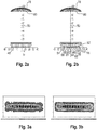
- FIG. 2 shows a prior art optical system in which main optical axes of coupling surfaces 48 extend approximately at a parallel distance from a system main optical axis 50.
- an optical system according to the invention in the form of a primary optics 52 shown are inclined in the main optical axes of coupling surfaces 54 to 76 with respect to the central coupling surfaces of the primary optics 52 and with respect to the main optical system axis 50.
- Secondary Optics are 78 in FIGS. 2a and 2b designed as approximately plano-convex lenses with an approximately plane coupling surface 80.
- the coupling surfaces 54 to 76 have the following angles of inclination: coupling surface 54 56 58 60 62 64 66 68 70 72 74 76 Inclination angle [°] -5.5 -5.5 -4.5 -1.5 0 0 0 0 1.5 4.5 5.5 5.5
- FIG. 3a is a light intensity distribution on the output side of the secondary optics 78 off FIG. 2a and in FIG. 3b a light intensity distribution on the output side of the secondary optics 78 FIG. 2b shows.
- FIG. 3b can be seen that, especially in the edge region (edge pixels), a homogeneous illumination in comparison to FIG. 3a is present.
- FIG. 3a Prior art
- FIG. 3a are given, especially at the edge, disadvantageous crescent-like illuminations or a rather inhomogeneous illumination.
- an optic for a matrix headlight with a large number of coupling surfaces An optical main axis at least one coupling-in surface is inclined in this case towards a main optical axis of the entire optical system.
Landscapes
- Physics & Mathematics (AREA)
- Engineering & Computer Science (AREA)
- General Engineering & Computer Science (AREA)
- Optics & Photonics (AREA)
- General Physics & Mathematics (AREA)
- Microelectronics & Electronic Packaging (AREA)
- Mathematical Physics (AREA)
- Non-Portable Lighting Devices Or Systems Thereof (AREA)
Applications Claiming Priority (1)
| Application Number | Priority Date | Filing Date | Title |
|---|---|---|---|
| DE102016217130.5A DE102016217130A1 (de) | 2016-09-08 | 2016-09-08 | Optik und optisches System |
Publications (2)
| Publication Number | Publication Date |
|---|---|
| EP3293557A1 true EP3293557A1 (fr) | 2018-03-14 |
| EP3293557B1 EP3293557B1 (fr) | 2021-12-22 |
Family
ID=59713897
Family Applications (1)
| Application Number | Title | Priority Date | Filing Date |
|---|---|---|---|
| EP17187996.8A Active EP3293557B1 (fr) | 2016-09-08 | 2017-08-25 | Optique et système optique |
Country Status (2)
| Country | Link |
|---|---|
| EP (1) | EP3293557B1 (fr) |
| DE (1) | DE102016217130A1 (fr) |
Cited By (1)
| Publication number | Priority date | Publication date | Assignee | Title |
|---|---|---|---|---|
| WO2020057765A1 (fr) * | 2018-09-19 | 2020-03-26 | Osram Oled Gmbh | Dispositif d'émission de lumière et procédé de fabrication de celui-ci |
Citations (3)
| Publication number | Priority date | Publication date | Assignee | Title |
|---|---|---|---|---|
| DE102009053581B3 (de) * | 2009-10-05 | 2011-03-03 | Automotive Lighting Reutlingen Gmbh | Lichtmodul für eine Beleuchtungseinrichtung eines Kraftfahrzeugs |
| EP2357399A1 (fr) * | 2010-02-16 | 2011-08-17 | Koito Manufacturing Co., Ltd. | Unité optique |
| AT512246A1 (de) * | 2011-11-22 | 2013-06-15 | Zizala Lichtsysteme Gmbh | Led-projektionsmodul und scheinwerfer mit modul |
-
2016
- 2016-09-08 DE DE102016217130.5A patent/DE102016217130A1/de not_active Withdrawn
-
2017
- 2017-08-25 EP EP17187996.8A patent/EP3293557B1/fr active Active
Patent Citations (3)
| Publication number | Priority date | Publication date | Assignee | Title |
|---|---|---|---|---|
| DE102009053581B3 (de) * | 2009-10-05 | 2011-03-03 | Automotive Lighting Reutlingen Gmbh | Lichtmodul für eine Beleuchtungseinrichtung eines Kraftfahrzeugs |
| EP2357399A1 (fr) * | 2010-02-16 | 2011-08-17 | Koito Manufacturing Co., Ltd. | Unité optique |
| AT512246A1 (de) * | 2011-11-22 | 2013-06-15 | Zizala Lichtsysteme Gmbh | Led-projektionsmodul und scheinwerfer mit modul |
Cited By (1)
| Publication number | Priority date | Publication date | Assignee | Title |
|---|---|---|---|---|
| WO2020057765A1 (fr) * | 2018-09-19 | 2020-03-26 | Osram Oled Gmbh | Dispositif d'émission de lumière et procédé de fabrication de celui-ci |
Also Published As
| Publication number | Publication date |
|---|---|
| DE102016217130A1 (de) | 2018-03-08 |
| EP3293557B1 (fr) | 2021-12-22 |
Similar Documents
| Publication | Publication Date | Title |
|---|---|---|
| EP3330597B1 (fr) | Optique primaire, optique secondaire, module, dispositif, phares de véhicule automobile et système de phares | |
| EP1630576A2 (fr) | Projecteur avec un faisceau lumineux prédéfini et élément optique primaire pour un projecteur | |
| EP3473918B1 (fr) | Dispositif d'éclairage pour un phare de véhicule automobile | |
| WO2006045545A1 (fr) | Lentille et microreseau de lentilles | |
| DE10314524A1 (de) | Scheinwerfer und Scheinwerferelement | |
| DE102017206194A1 (de) | Lichtleiter, Optik, Beleuchtungssytem und Scheinwerfer | |
| DE102015226633A1 (de) | Leuchtvorrichtung mit einem Halbleiterlaser und einer Linseneinrichtung | |
| WO2014001046A1 (fr) | Composant photoémetteur organique | |
| DE102017206817B4 (de) | Beleuchtungssystem und scheinwerfer | |
| DE102016216364A1 (de) | Beleuchtungssystem, fahrzeugscheinwerfer und verfahren zum steuern eines beleuchtungssystems | |
| DE102018207063A1 (de) | Optik, optische anordnung und scheinwerfer | |
| EP3516688B1 (fr) | Phare de véhicule à moteur avec del smd soudée | |
| DE102014221668A1 (de) | Beleuchtungsvorrichtung | |
| DE102017213103A1 (de) | Beleuchtungssystem und scheinwerfer | |
| DE102018206709A1 (de) | Beleuchtungssystem und scheinwerfer | |
| EP3293557B1 (fr) | Optique et système optique | |
| WO2009089973A1 (fr) | Module de del avec une lentille | |
| DE102017208241A1 (de) | Lichtleiter zum erzeugen eines vorgegebenen lichtbilds eines pixels einer matrixleuchte | |
| EP3190617A1 (fr) | Dispositif électroluminescent et procédé de fabrication d'un dispositif électroluminescent | |
| AT518334B1 (de) | Matrix-beleuchtungs-modul | |
| WO2018041609A1 (fr) | Module et système d'éclairage | |
| DE102017208122B4 (de) | Optische Anordnung und Scheinwerfer | |
| DE102017205609A1 (de) | Beleuchtungsanordnung und Scheinwerfer | |
| WO2017174659A1 (fr) | Source de lumière pour dispositif d'éclairage et dispositif d'éclairage équipé d'une telle source de lumière | |
| DE102017223303A1 (de) | Optik, optische anordnung und scheinwerfer |
Legal Events
| Date | Code | Title | Description |
|---|---|---|---|
| PUAI | Public reference made under article 153(3) epc to a published international application that has entered the european phase |
Free format text: ORIGINAL CODE: 0009012 |
|
| STAA | Information on the status of an ep patent application or granted ep patent |
Free format text: STATUS: THE APPLICATION HAS BEEN PUBLISHED |
|
| AK | Designated contracting states |
Kind code of ref document: A1 Designated state(s): AL AT BE BG CH CY CZ DE DK EE ES FI FR GB GR HR HU IE IS IT LI LT LU LV MC MK MT NL NO PL PT RO RS SE SI SK SM TR |
|
| AX | Request for extension of the european patent |
Extension state: BA ME |
|
| STAA | Information on the status of an ep patent application or granted ep patent |
Free format text: STATUS: REQUEST FOR EXAMINATION WAS MADE |
|
| 17P | Request for examination filed |
Effective date: 20180914 |
|
| RBV | Designated contracting states (corrected) |
Designated state(s): AL AT BE BG CH CY CZ DE DK EE ES FI FR GB GR HR HU IE IS IT LI LT LU LV MC MK MT NL NO PL PT RO RS SE SI SK SM TR |
|
| RAP1 | Party data changed (applicant data changed or rights of an application transferred) |
Owner name: OSRAM GMBH |
|
| GRAP | Despatch of communication of intention to grant a patent |
Free format text: ORIGINAL CODE: EPIDOSNIGR1 |
|
| STAA | Information on the status of an ep patent application or granted ep patent |
Free format text: STATUS: GRANT OF PATENT IS INTENDED |
|
| INTG | Intention to grant announced |
Effective date: 20210722 |
|
| GRAS | Grant fee paid |
Free format text: ORIGINAL CODE: EPIDOSNIGR3 |
|
| GRAA | (expected) grant |
Free format text: ORIGINAL CODE: 0009210 |
|
| STAA | Information on the status of an ep patent application or granted ep patent |
Free format text: STATUS: THE PATENT HAS BEEN GRANTED |
|
| AK | Designated contracting states |
Kind code of ref document: B1 Designated state(s): AL AT BE BG CH CY CZ DE DK EE ES FI FR GB GR HR HU IE IS IT LI LT LU LV MC MK MT NL NO PL PT RO RS SE SI SK SM TR |
|
| REG | Reference to a national code |
Ref country code: GB Ref legal event code: FG4D Free format text: NOT ENGLISH |
|
| REG | Reference to a national code |
Ref country code: CH Ref legal event code: EP |
|
| REG | Reference to a national code |
Ref country code: DE Ref legal event code: R096 Ref document number: 502017012280 Country of ref document: DE |
|
| REG | Reference to a national code |
Ref country code: AT Ref legal event code: REF Ref document number: 1457427 Country of ref document: AT Kind code of ref document: T Effective date: 20220115 |
|
| REG | Reference to a national code |
Ref country code: IE Ref legal event code: FG4D Free format text: LANGUAGE OF EP DOCUMENT: GERMAN |
|
| REG | Reference to a national code |
Ref country code: LT Ref legal event code: MG9D |
|
| PG25 | Lapsed in a contracting state [announced via postgrant information from national office to epo] |
Ref country code: RS Free format text: LAPSE BECAUSE OF FAILURE TO SUBMIT A TRANSLATION OF THE DESCRIPTION OR TO PAY THE FEE WITHIN THE PRESCRIBED TIME-LIMIT Effective date: 20211222 Ref country code: LT Free format text: LAPSE BECAUSE OF FAILURE TO SUBMIT A TRANSLATION OF THE DESCRIPTION OR TO PAY THE FEE WITHIN THE PRESCRIBED TIME-LIMIT Effective date: 20211222 Ref country code: FI Free format text: LAPSE BECAUSE OF FAILURE TO SUBMIT A TRANSLATION OF THE DESCRIPTION OR TO PAY THE FEE WITHIN THE PRESCRIBED TIME-LIMIT Effective date: 20211222 Ref country code: BG Free format text: LAPSE BECAUSE OF FAILURE TO SUBMIT A TRANSLATION OF THE DESCRIPTION OR TO PAY THE FEE WITHIN THE PRESCRIBED TIME-LIMIT Effective date: 20220322 |
|
| REG | Reference to a national code |
Ref country code: NL Ref legal event code: MP Effective date: 20211222 |
|
| PG25 | Lapsed in a contracting state [announced via postgrant information from national office to epo] |
Ref country code: SE Free format text: LAPSE BECAUSE OF FAILURE TO SUBMIT A TRANSLATION OF THE DESCRIPTION OR TO PAY THE FEE WITHIN THE PRESCRIBED TIME-LIMIT Effective date: 20211222 Ref country code: NO Free format text: LAPSE BECAUSE OF FAILURE TO SUBMIT A TRANSLATION OF THE DESCRIPTION OR TO PAY THE FEE WITHIN THE PRESCRIBED TIME-LIMIT Effective date: 20220322 Ref country code: LV Free format text: LAPSE BECAUSE OF FAILURE TO SUBMIT A TRANSLATION OF THE DESCRIPTION OR TO PAY THE FEE WITHIN THE PRESCRIBED TIME-LIMIT Effective date: 20211222 Ref country code: HR Free format text: LAPSE BECAUSE OF FAILURE TO SUBMIT A TRANSLATION OF THE DESCRIPTION OR TO PAY THE FEE WITHIN THE PRESCRIBED TIME-LIMIT Effective date: 20211222 Ref country code: GR Free format text: LAPSE BECAUSE OF FAILURE TO SUBMIT A TRANSLATION OF THE DESCRIPTION OR TO PAY THE FEE WITHIN THE PRESCRIBED TIME-LIMIT Effective date: 20220323 |
|
| PG25 | Lapsed in a contracting state [announced via postgrant information from national office to epo] |
Ref country code: NL Free format text: LAPSE BECAUSE OF FAILURE TO SUBMIT A TRANSLATION OF THE DESCRIPTION OR TO PAY THE FEE WITHIN THE PRESCRIBED TIME-LIMIT Effective date: 20211222 |
|
| PG25 | Lapsed in a contracting state [announced via postgrant information from national office to epo] |
Ref country code: SM Free format text: LAPSE BECAUSE OF FAILURE TO SUBMIT A TRANSLATION OF THE DESCRIPTION OR TO PAY THE FEE WITHIN THE PRESCRIBED TIME-LIMIT Effective date: 20211222 Ref country code: SK Free format text: LAPSE BECAUSE OF FAILURE TO SUBMIT A TRANSLATION OF THE DESCRIPTION OR TO PAY THE FEE WITHIN THE PRESCRIBED TIME-LIMIT Effective date: 20211222 Ref country code: RO Free format text: LAPSE BECAUSE OF FAILURE TO SUBMIT A TRANSLATION OF THE DESCRIPTION OR TO PAY THE FEE WITHIN THE PRESCRIBED TIME-LIMIT Effective date: 20211222 Ref country code: PT Free format text: LAPSE BECAUSE OF FAILURE TO SUBMIT A TRANSLATION OF THE DESCRIPTION OR TO PAY THE FEE WITHIN THE PRESCRIBED TIME-LIMIT Effective date: 20220422 Ref country code: ES Free format text: LAPSE BECAUSE OF FAILURE TO SUBMIT A TRANSLATION OF THE DESCRIPTION OR TO PAY THE FEE WITHIN THE PRESCRIBED TIME-LIMIT Effective date: 20211222 Ref country code: EE Free format text: LAPSE BECAUSE OF FAILURE TO SUBMIT A TRANSLATION OF THE DESCRIPTION OR TO PAY THE FEE WITHIN THE PRESCRIBED TIME-LIMIT Effective date: 20211222 Ref country code: CZ Free format text: LAPSE BECAUSE OF FAILURE TO SUBMIT A TRANSLATION OF THE DESCRIPTION OR TO PAY THE FEE WITHIN THE PRESCRIBED TIME-LIMIT Effective date: 20211222 |
|
| PG25 | Lapsed in a contracting state [announced via postgrant information from national office to epo] |
Ref country code: PL Free format text: LAPSE BECAUSE OF FAILURE TO SUBMIT A TRANSLATION OF THE DESCRIPTION OR TO PAY THE FEE WITHIN THE PRESCRIBED TIME-LIMIT Effective date: 20211222 |
|
| REG | Reference to a national code |
Ref country code: DE Ref legal event code: R097 Ref document number: 502017012280 Country of ref document: DE |
|
| PG25 | Lapsed in a contracting state [announced via postgrant information from national office to epo] |
Ref country code: IS Free format text: LAPSE BECAUSE OF FAILURE TO SUBMIT A TRANSLATION OF THE DESCRIPTION OR TO PAY THE FEE WITHIN THE PRESCRIBED TIME-LIMIT Effective date: 20220422 |
|
| PLBE | No opposition filed within time limit |
Free format text: ORIGINAL CODE: 0009261 |
|
| STAA | Information on the status of an ep patent application or granted ep patent |
Free format text: STATUS: NO OPPOSITION FILED WITHIN TIME LIMIT |
|
| PG25 | Lapsed in a contracting state [announced via postgrant information from national office to epo] |
Ref country code: DK Free format text: LAPSE BECAUSE OF FAILURE TO SUBMIT A TRANSLATION OF THE DESCRIPTION OR TO PAY THE FEE WITHIN THE PRESCRIBED TIME-LIMIT Effective date: 20211222 Ref country code: AL Free format text: LAPSE BECAUSE OF FAILURE TO SUBMIT A TRANSLATION OF THE DESCRIPTION OR TO PAY THE FEE WITHIN THE PRESCRIBED TIME-LIMIT Effective date: 20211222 |
|
| 26N | No opposition filed |
Effective date: 20220923 |
|
| PG25 | Lapsed in a contracting state [announced via postgrant information from national office to epo] |
Ref country code: SI Free format text: LAPSE BECAUSE OF FAILURE TO SUBMIT A TRANSLATION OF THE DESCRIPTION OR TO PAY THE FEE WITHIN THE PRESCRIBED TIME-LIMIT Effective date: 20211222 |
|
| PG25 | Lapsed in a contracting state [announced via postgrant information from national office to epo] |
Ref country code: MC Free format text: LAPSE BECAUSE OF FAILURE TO SUBMIT A TRANSLATION OF THE DESCRIPTION OR TO PAY THE FEE WITHIN THE PRESCRIBED TIME-LIMIT Effective date: 20211222 |
|
| REG | Reference to a national code |
Ref country code: CH Ref legal event code: PL |
|
| GBPC | Gb: european patent ceased through non-payment of renewal fee |
Effective date: 20220825 |
|
| PG25 | Lapsed in a contracting state [announced via postgrant information from national office to epo] |
Ref country code: LU Free format text: LAPSE BECAUSE OF NON-PAYMENT OF DUE FEES Effective date: 20220825 Ref country code: LI Free format text: LAPSE BECAUSE OF NON-PAYMENT OF DUE FEES Effective date: 20220831 Ref country code: CH Free format text: LAPSE BECAUSE OF NON-PAYMENT OF DUE FEES Effective date: 20220831 |
|
| REG | Reference to a national code |
Ref country code: BE Ref legal event code: MM Effective date: 20220831 |
|
| PG25 | Lapsed in a contracting state [announced via postgrant information from national office to epo] |
Ref country code: IT Free format text: LAPSE BECAUSE OF FAILURE TO SUBMIT A TRANSLATION OF THE DESCRIPTION OR TO PAY THE FEE WITHIN THE PRESCRIBED TIME-LIMIT Effective date: 20211222 |
|
| PG25 | Lapsed in a contracting state [announced via postgrant information from national office to epo] |
Ref country code: IE Free format text: LAPSE BECAUSE OF NON-PAYMENT OF DUE FEES Effective date: 20220825 |
|
| P01 | Opt-out of the competence of the unified patent court (upc) registered |
Effective date: 20230821 |
|
| PG25 | Lapsed in a contracting state [announced via postgrant information from national office to epo] |
Ref country code: BE Free format text: LAPSE BECAUSE OF NON-PAYMENT OF DUE FEES Effective date: 20220831 |
|
| REG | Reference to a national code |
Ref country code: AT Ref legal event code: MM01 Ref document number: 1457427 Country of ref document: AT Kind code of ref document: T Effective date: 20220825 |
|
| PG25 | Lapsed in a contracting state [announced via postgrant information from national office to epo] |
Ref country code: GB Free format text: LAPSE BECAUSE OF NON-PAYMENT OF DUE FEES Effective date: 20220825 Ref country code: AT Free format text: LAPSE BECAUSE OF NON-PAYMENT OF DUE FEES Effective date: 20220825 |
|
| PG25 | Lapsed in a contracting state [announced via postgrant information from national office to epo] |
Ref country code: HU Free format text: LAPSE BECAUSE OF FAILURE TO SUBMIT A TRANSLATION OF THE DESCRIPTION OR TO PAY THE FEE WITHIN THE PRESCRIBED TIME-LIMIT; INVALID AB INITIO Effective date: 20170825 |
|
| PG25 | Lapsed in a contracting state [announced via postgrant information from national office to epo] |
Ref country code: CY Free format text: LAPSE BECAUSE OF FAILURE TO SUBMIT A TRANSLATION OF THE DESCRIPTION OR TO PAY THE FEE WITHIN THE PRESCRIBED TIME-LIMIT Effective date: 20211222 |
|
| PG25 | Lapsed in a contracting state [announced via postgrant information from national office to epo] |
Ref country code: MK Free format text: LAPSE BECAUSE OF FAILURE TO SUBMIT A TRANSLATION OF THE DESCRIPTION OR TO PAY THE FEE WITHIN THE PRESCRIBED TIME-LIMIT Effective date: 20211222 |
|
| PG25 | Lapsed in a contracting state [announced via postgrant information from national office to epo] |
Ref country code: MT Free format text: LAPSE BECAUSE OF FAILURE TO SUBMIT A TRANSLATION OF THE DESCRIPTION OR TO PAY THE FEE WITHIN THE PRESCRIBED TIME-LIMIT Effective date: 20211222 |
|
| REG | Reference to a national code |
Ref country code: DE Ref legal event code: R082 Ref document number: 502017012280 Country of ref document: DE Representative=s name: IMPULS LEGAL PARTG MBB, DE |
|
| PGFP | Annual fee paid to national office [announced via postgrant information from national office to epo] |
Ref country code: DE Payment date: 20250820 Year of fee payment: 9 |
|
| PGFP | Annual fee paid to national office [announced via postgrant information from national office to epo] |
Ref country code: FR Payment date: 20250828 Year of fee payment: 9 |
|
| PG25 | Lapsed in a contracting state [announced via postgrant information from national office to epo] |
Ref country code: TR Free format text: LAPSE BECAUSE OF FAILURE TO SUBMIT A TRANSLATION OF THE DESCRIPTION OR TO PAY THE FEE WITHIN THE PRESCRIBED TIME-LIMIT Effective date: 20211222 |