EP3293559A1 - Microscope - Google Patents
Microscope Download PDFInfo
- Publication number
- EP3293559A1 EP3293559A1 EP17186629.6A EP17186629A EP3293559A1 EP 3293559 A1 EP3293559 A1 EP 3293559A1 EP 17186629 A EP17186629 A EP 17186629A EP 3293559 A1 EP3293559 A1 EP 3293559A1
- Authority
- EP
- European Patent Office
- Prior art keywords
- light
- objective lens
- specimen
- section
- container
- Prior art date
- Legal status (The legal status is an assumption and is not a legal conclusion. Google has not performed a legal analysis and makes no representation as to the accuracy of the status listed.)
- Withdrawn
Links
- 238000007654 immersion Methods 0.000 claims abstract description 177
- 238000001514 detection method Methods 0.000 claims abstract description 94
- 239000007788 liquid Substances 0.000 claims abstract description 83
- 230000008685 targeting Effects 0.000 claims abstract description 22
- 238000005286 illumination Methods 0.000 claims description 79
- 230000003287 optical effect Effects 0.000 claims description 75
- 230000004308 accommodation Effects 0.000 claims description 25
- 238000003384 imaging method Methods 0.000 claims description 24
- 239000013307 optical fiber Substances 0.000 description 21
- 230000008859 change Effects 0.000 description 13
- 238000010586 diagram Methods 0.000 description 8
- 238000000034 method Methods 0.000 description 7
- 238000002073 fluorescence micrograph Methods 0.000 description 6
- 230000004048 modification Effects 0.000 description 6
- 238000012986 modification Methods 0.000 description 6
- 230000004075 alteration Effects 0.000 description 5
- XLYOFNOQVPJJNP-UHFFFAOYSA-N water Substances O XLYOFNOQVPJJNP-UHFFFAOYSA-N 0.000 description 5
- 238000005562 fading Methods 0.000 description 3
- 238000004519 manufacturing process Methods 0.000 description 3
- 230000007246 mechanism Effects 0.000 description 3
- 230000008901 benefit Effects 0.000 description 2
- 239000000835 fiber Substances 0.000 description 2
- 238000004020 luminiscence type Methods 0.000 description 2
- 230000000638 stimulation Effects 0.000 description 2
- 239000000126 substance Substances 0.000 description 2
- OYPRJOBELJOOCE-UHFFFAOYSA-N Calcium Chemical compound [Ca] OYPRJOBELJOOCE-UHFFFAOYSA-N 0.000 description 1
- 241000252212 Danio rerio Species 0.000 description 1
- 238000010521 absorption reaction Methods 0.000 description 1
- 238000003491 array Methods 0.000 description 1
- 229910052791 calcium Inorganic materials 0.000 description 1
- 239000011575 calcium Substances 0.000 description 1
- 210000004027 cell Anatomy 0.000 description 1
- 238000012937 correction Methods 0.000 description 1
- 210000004748 cultured cell Anatomy 0.000 description 1
- 238000013461 design Methods 0.000 description 1
- 238000009509 drug development Methods 0.000 description 1
- 230000000694 effects Effects 0.000 description 1
- 102000034287 fluorescent proteins Human genes 0.000 description 1
- 108091006047 fluorescent proteins Proteins 0.000 description 1
- 238000010191 image analysis Methods 0.000 description 1
- 230000001678 irradiating effect Effects 0.000 description 1
- 238000005259 measurement Methods 0.000 description 1
- 210000000056 organ Anatomy 0.000 description 1
- 210000002220 organoid Anatomy 0.000 description 1
- 230000002093 peripheral effect Effects 0.000 description 1
- 230000005855 radiation Effects 0.000 description 1
- 230000004044 response Effects 0.000 description 1
- 238000012216 screening Methods 0.000 description 1
- 238000007789 sealing Methods 0.000 description 1
Images


Classifications
-
- G—PHYSICS
- G02—OPTICS
- G02B—OPTICAL ELEMENTS, SYSTEMS OR APPARATUS
- G02B21/00—Microscopes
- G02B21/33—Immersion oils, or microscope systems or objectives for use with immersion fluids
-
- G—PHYSICS
- G01—MEASURING; TESTING
- G01N—INVESTIGATING OR ANALYSING MATERIALS BY DETERMINING THEIR CHEMICAL OR PHYSICAL PROPERTIES
- G01N21/00—Investigating or analysing materials by the use of optical means, i.e. using sub-millimetre waves, infrared, visible or ultraviolet light
- G01N21/01—Arrangements or apparatus for facilitating the optical investigation
- G01N21/03—Cuvette constructions
- G01N21/0303—Optical path conditioning in cuvettes, e.g. windows; adapted optical elements or systems; path modifying or adjustment
-
- G—PHYSICS
- G01—MEASURING; TESTING
- G01N—INVESTIGATING OR ANALYSING MATERIALS BY DETERMINING THEIR CHEMICAL OR PHYSICAL PROPERTIES
- G01N21/00—Investigating or analysing materials by the use of optical means, i.e. using sub-millimetre waves, infrared, visible or ultraviolet light
- G01N21/62—Systems in which the material investigated is excited whereby it emits light or causes a change in wavelength of the incident light
- G01N21/63—Systems in which the material investigated is excited whereby it emits light or causes a change in wavelength of the incident light optically excited
- G01N21/64—Fluorescence; Phosphorescence
- G01N21/645—Specially adapted constructive features of fluorimeters
- G01N21/6456—Spatial resolved fluorescence measurements; Imaging
- G01N21/6458—Fluorescence microscopy
-
- G—PHYSICS
- G02—OPTICS
- G02B—OPTICAL ELEMENTS, SYSTEMS OR APPARATUS
- G02B21/00—Microscopes
- G02B21/0004—Microscopes specially adapted for specific applications
- G02B21/002—Scanning microscopes
- G02B21/0024—Confocal scanning microscopes (CSOMs) or confocal "macroscopes"; Accessories which are not restricted to use with CSOMs, e.g. sample holders
- G02B21/0052—Optical details of the image generation
- G02B21/006—Optical details of the image generation focusing arrangements; selection of the plane to be imaged
-
- G—PHYSICS
- G02—OPTICS
- G02B—OPTICAL ELEMENTS, SYSTEMS OR APPARATUS
- G02B21/00—Microscopes
- G02B21/0004—Microscopes specially adapted for specific applications
- G02B21/0088—Inverse microscopes
-
- G—PHYSICS
- G02—OPTICS
- G02B—OPTICAL ELEMENTS, SYSTEMS OR APPARATUS
- G02B21/00—Microscopes
- G02B21/06—Means for illuminating specimens
- G02B21/08—Condensers
- G02B21/086—Condensers for transillumination only
-
- G—PHYSICS
- G02—OPTICS
- G02B—OPTICAL ELEMENTS, SYSTEMS OR APPARATUS
- G02B21/00—Microscopes
- G02B21/16—Microscopes adapted for ultraviolet illumination ; Fluorescence microscopes
-
- G—PHYSICS
- G02—OPTICS
- G02B—OPTICAL ELEMENTS, SYSTEMS OR APPARATUS
- G02B21/00—Microscopes
- G02B21/18—Arrangements with more than one light path, e.g. for comparing two specimens
- G02B21/20—Binocular arrangements
- G02B21/22—Stereoscopic arrangements
-
- G—PHYSICS
- G02—OPTICS
- G02B—OPTICAL ELEMENTS, SYSTEMS OR APPARATUS
- G02B21/00—Microscopes
- G02B21/24—Base structure
- G02B21/26—Stages; Adjusting means therefor
-
- G—PHYSICS
- G02—OPTICS
- G02B—OPTICAL ELEMENTS, SYSTEMS OR APPARATUS
- G02B21/00—Microscopes
- G02B21/34—Microscope slides, e.g. mounting specimens on microscope slides
-
- G—PHYSICS
- G02—OPTICS
- G02B—OPTICAL ELEMENTS, SYSTEMS OR APPARATUS
- G02B21/00—Microscopes
- G02B21/36—Microscopes arranged for photographic purposes or projection purposes or digital imaging or video purposes including associated control and data processing arrangements
- G02B21/361—Optical details, e.g. image relay to the camera or image sensor
-
- G—PHYSICS
- G01—MEASURING; TESTING
- G01N—INVESTIGATING OR ANALYSING MATERIALS BY DETERMINING THEIR CHEMICAL OR PHYSICAL PROPERTIES
- G01N21/00—Investigating or analysing materials by the use of optical means, i.e. using sub-millimetre waves, infrared, visible or ultraviolet light
- G01N21/01—Arrangements or apparatus for facilitating the optical investigation
- G01N21/03—Cuvette constructions
- G01N2021/0342—Solid sample being immersed, e.g. equiindex fluid
-
- G—PHYSICS
- G01—MEASURING; TESTING
- G01N—INVESTIGATING OR ANALYSING MATERIALS BY DETERMINING THEIR CHEMICAL OR PHYSICAL PROPERTIES
- G01N21/00—Investigating or analysing materials by the use of optical means, i.e. using sub-millimetre waves, infrared, visible or ultraviolet light
- G01N21/01—Arrangements or apparatus for facilitating the optical investigation
- G01N21/03—Cuvette constructions
- G01N2021/0367—Supports of cells, e.g. pivotable
Definitions
- the present invention relates to a microscope.
- this technique is gaining attention not only as a technique for the purpose of obtaining a stereoscopic image of a living organism, such as zebrafish, in which target molecules are labeled with fluorescent proteins, but also as a technique that is applied to so-called drug development screening, in which pharmaceutical efficacy is evaluated by using an image analysis technique by obtaining a three-dimensional stereoscopic image of three-dimensional cultured cells, such as spheroids or organoids (artificial organ or a portion thereof), thus raising expectations for use in a wide range of applications.
- an image analysis technique by obtaining a three-dimensional stereoscopic image of three-dimensional cultured cells, such as spheroids or organoids (artificial organ or a portion thereof)
- spheroids or organoids artificial organ or a portion thereof
- An immersion objective lens is used with this observation method in the microscopes described in Patent Literatures 1 and 2.
- the microscope described in Patent Literature 1 when an observation position is changed by moving the container relative to the objective lens, the amount of the liquid immersion medium reserved between the objective lens and the container is reduced, and hence the liquid immersion medium needs to be replenished.
- this causes an inconvenience in that the longer the relative moving distance between the objective lens and the container, such as in cases where the container is composed of a plurality of arrays, the more frequently the liquid immersion medium needs to be replenished, requiring a large amount of liquid immersion medium to be prepared.
- replenishment takes a long time, the total observation time becomes longer as replenishment becomes more frequent.
- the present invention has been conceived in light of the above-described circumstances, and an object thereof is to provide a microscope that prevents a liquid immersion medium from running out while still reducing the amount of the liquid immersion medium and the replenishment frequency thereof with a simple and inexpensive structure, thereby achieving highly reliable observation.
- the present invention provides the following solutions.
- One aspect of the present invention is a microscope including: a medium container that stores a second liquid immersion medium in which a specimen container accommodating a first liquid immersion medium together with a specimen is immersed and that has an index of refraction identical to that of the first liquid immersion medium; an objective lens that is placed outside the medium container and that collects light emitted from the specimen; an image-capturing unit that acquires an image of the light collected by the objective lens; a targeting section that moves a focal position of the objective lens in a direction along a detection light axis thereof; and a movable stage that supports the specimen container in the medium container such that the specimen container can move at least in a direction along the detection light axis, wherein each of the specimen container and the medium container has a light-transmitting section capable of transmitting the light from the specimen, and the objective lens is disposed so as to face the light-transmitting section of the specimen container, with the light-transmitting section of the medium container interposed therebetween.
- the specimen is accommodated in the specimen container with the first liquid immersion medium, and then the specimen container as a whole is immersed into the second liquid immersion medium in the medium container. Thereafter, the light emitted from the specimen passes through the first liquid immersion medium, the light-transmitting section of the specimen container, the second liquid immersion medium having an index of refraction identical to that of the first liquid immersion medium, and the light-transmitting section of the medium container, is collected by the objective lens, and is imaged by the image-capturing unit. Therefore, by moving the specimen container in the medium container in a direction along the detection light axis of the objective lens by using the movable stage, a cross-sectional image of the specimen intersecting the detection light axis of the objective lens can be acquired.
- the shift in the focal position can be eliminated by finely adjusting the position in a direction along the detection light axis of the objective lens using the targeting section.
- the objective lens may be disposed with a space interposed between the objective lens and the light-transmitting section of the medium container.
- the, objective lens can be switched to another with a different magnification.
- the objective lens may be an immersion objective lens, and the immersion objective lens may be disposed with a third liquid immersion medium interposed between the immersion objective lens and the light-transmitting section of the medium container.
- the numerical aperture (NA) of the immersion objective lens can be increased, thereby making it possible to obtain higher resolution.
- the numerical aperture (NA) of the immersion objective lens can be increased, thereby making it possible to obtain higher resolution.
- movement of the specimen container does not cause the amount of the third liquid immersion medium to change, it is not necessary to prepare a large amount of the third liquid immersion medium or replenish the third liquid immersion medium so frequently.
- the third liquid immersion medium does not run out.
- the immersion objective lens may be disposed with the detection light axis oriented in a direction intersecting a vertical direction, and the third liquid immersion medium may be held between the immersion objective lens and the light-transmitting section of the medium container due to surface tension.
- the specimen container and the medium container may have the light-transmitting sections at side wall sections, and the immersion objective lens may be disposed with the detection light axis oriented in a direction substantially orthogonal to the vertical direction.
- the immersion objective lens can be placed laterally with respect to the medium container, adjacently to the light-transmitting section at the side wall section with the third liquid immersion medium interposed therebetween.
- the third liquid immersion medium may have an index of refraction identical to that of the second liquid immersion medium.
- the light-transmitting section of the specimen container may have an index of refraction identical to that of the second liquid immersion medium.
- the light-transmitting section of the medium container may have an index of refraction identical to that of the second liquid immersion medium.
- the movable stage may support the specimen container so as to be movable in a direction intersecting the detection light axis.
- the observation position of the specimen can be changed in a direction intersecting the detection light axis of the objective lens.
- the image-capturing unit may acquire an image of the light self-emitted by the specimen.
- a luminescence microscope can be configured, and therefore, the configuration can be made all the more simple and inexpensive because no light source or illumination optical system is required.
- the above-described aspect may include an illumination optical system that irradiates the specimen with light from a direction intersecting the detection light axis, wherein each of the specimen container and the medium container may have a light transmitting section that transmits, towards the specimen, the light coming from the illumination optical system.
- the specimen can be irradiated with the light emitted by the illumination optical system, from the sides of the medium container and the specimen container and via each of the light transmitting sections.
- the medium container may have the light transmitting section at a bottom section
- the illumination optical system may include a reflection mirror placed in the medium container and may cause the light to enter the medium container via the light transmitting section at the bottom section and to reflect the light at the reflection mirror towards the specimen.
- the illumination optical system excluding the reflection mirror, can be placed below the medium container.
- the illumination optical system excluding the reflection mirror, can be placed below the medium container.
- the medium container may have the light transmitting section at a side wall section, and the illumination optical system may cause the light to enter the medium container via the light transmitting section at the side wall section.
- the illumination optical system can be placed laterally with respect to the medium container.
- the microscope can be configured merely by adding a medium container, a movable stage, and an illumination optical system to a conventional inverted microscope provided with an objective lens, a targeting section, and an image-capturing unit.
- the illumination optical system may include a lens that is placed in the medium container and that has positive refractive power.
- the emission NA of the lens needs to be set to be larger.
- the emission NA of the lens can be set to be larger.
- the lens having positive refractive power may be a cylindrical lens having positive refractive power in one direction intersecting an illumination light axis of the illumination optical system.
- the light can be focused by the cylindrical lens into the form of a flat surface along a plane intersecting the detection light axis of the detection optical system and made to enter the specimen.
- the focal plane of the objective lens coincide with the incident plane of the light, the light produced in a wide area along the focal plane can be collected all at once by the objective lens, thereby making it possible to acquire an image with higher resolution.
- the above-described aspect may include a microlens array formed by two-dimensionally arranging a plurality of microlenses in directions intersecting an imaging light axis of the image-capturing unit, wherein the illumination optical system may cause the light in the form of a substantially collimated beam to enter the specimen.
- the focal plane of the objective lens coincide with the incident area of the light
- the light produced in a wide area along the focal plane can be collected all at once by the objective lens.
- a plurality of items of image information having different parallaxes can be obtained all at once by acquiring, with the image-capturing unit, an image projected by the microlens array.
- the movable stage may support a plurality of the specimen containers so as to be movable in the medium container about an axis parallel to the detection light axis.
- the specimen container placed on the detection light axis can be switched merely by moving, with the movable stage, the plurality of specimen containers about an axis parallel to the detection light axis. Therefore, successive acquisition of images with the image-capturing unit is possible by sequentially radiating, with the illumination optical system, light onto the specimen in each of the specimen containers and sequentially collecting, with objective lens, light from the specimen in each of the specimen containers. By doing so, images of a large number of specimens can be acquired in an efficient and fast manner.
- the specimen container may have a plurality of specimen accommodation sections arranged in one direction intersecting the illumination light axis of the illumination optical system, and the movable stage may support the specimen accommodation sections so as to be capable of switching the specimen accommodation section placed on the detection light axis.
- the movable stage may support the specimen container so as to be rotatable in the medium container about the detection light axis.
- the illumination optical system may cause the light in a flat shape to enter the specimen along a plane intersecting the detection light axis of the objective lens.
- the microscope according to the present invention affords an advantage in that highly reliable observation can be achieved by preventing a liquid immersion medium from running out while still reducing the amount of the liquid immersion medium and the replenishment frequency thereof with a simple and inexpensive structure.
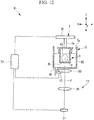
- a microscope 1 includes: a cuvette (specimen container) 3 for accommodating samples (specimens) S; a chamber (medium container) 5 that can accommodate the cuvette 3; a movable stage 7 for supporting the cuvette 3; an illumination optical system 9 for irradiating the samples S with a laser beam (light); an immersion objective lens (objective lens) 11 for collecting fluorescence emitted from the samples S; a targeting section 12 that can move the immersion objective lens 11 in a direction along a detection light axis P thereof; and an imaging optical system 13 for acquiring an image of the samples S on the basis of the fluorescence collected by the immersion objective lens 11.
- a cuvette for accommodating samples (specimens) S
- a chamber (medium container) 5 that can accommodate the cuvette 3
- a movable stage 7 for supporting the cuvette 3
- an illumination optical system 9 for irradiating the samples S with a laser beam (light)
- an immersion objective lens (objective lens) 11 for collecting fluorescence
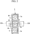
- the cuvette 3 has an array structure formed by arranging, in one direction, three accommodation sections (specimen accommodation sections) 3a for accommodating the samples S.
- Each of the accommodation sections 3a is filled with a cuvette solution (first liquid immersion medium) W1, such as a transparent solution, and the samples S are immersed in the respective cuvette solutions W1.
- Each of the samples S is made transparent as a result of being immersed in the cuvette solution W1.
- the cuvette 3 has, at side wall sections and a bottom section thereof, transparent sections (light transmitting sections) 3b that can transmit a laser beam and fluorescence, respectively.
- the chamber 5 has an opening 5a at the top section thereof and has, at the bottom section thereof, a transparent section (a light transmitting section) 5b that can transmit a laser beam and fluorescence.
- the transparent section 5b is formed in a wide area at the bottom section so as to cover illumination light axes Q of the illumination optical system 9 and the detection light axis P of the immersion objective lens 11.
- a chamber solution (second liquid immersion medium) W2 having an index of refraction substantially identical to that of the cuvette solution W1 is stored in this chamber 5, and the cuvette 3 is immersed in the chamber solution W2.
- the movable stage 7 includes an arm section 7a for holding the cuvette 3 and a support section 7b for supporting the arm section 7a.
- This movable stage 7 supports the cuvette 3 with the arm section 7a and the support section 7b such that the cuvette 3 is immersed in the chamber solution W2 via the opening 5a of the chamber 5 and that the transparent section 3b at the side wall sections are located on the illumination light axes Q.
- the movable stage 7 can move the held cuvette 3 in the vertical direction (hereinafter, referred to as the Z direction) and in two-dimensional directions (hereinafter, referred to as the X and Y directions) that intersect the vertical direction and that are orthogonal to each other. By doing so, the movable stage 7 can switch the accommodation section 3a of the cuvette 3 placed on the detection light axis P and change the observation position of the sample S in the same accommodation section 3a.
- the immersion objective lens 11 is composed by combining many lenses, not shown in the figure.
- This immersion objective lens 11 is disposed below the chamber 5 adjacently to the transparent section 5b at the bottom section and is placed face up so as to oppose the transparent section 5b.
- a liquid immersion solution (third liquid immersion medium) W3 such as pure water, is poured into the gap between an upper surface 11a of the lens at the most leading end of the immersion objective lens 11 and the transparent section 5b at the bottom section of the chamber 5, and the liquid immersion solution W3 is held in the gap due to the surface tension thereof.
- the targeting section 12 can finely adjust the focal position of the immersion objective lens 11 in a direction along the detection light axis P by finely moving the immersion objective lens 11 in the Z direction, within the range in which the surface tension of the liquid immersion solution W3 acts in the gap between the upper surface 11a of the lens at the most leading end of the immersion objective lens 11 and the transparent section 5b at the bottom section of the chamber 5.
- the illumination optical system 9 include: a laser light source 15 for producing a laser beam; an optical fiber 17 for guiding the laser beam emitted from the laser light source 15; convex lenses 19A and 19B for converting the laser beam guided via the optical fiber 17 into a collimated beam; cylindrical lenses (lenses) 21A and 21B for focusing the laser beam converted into a collimated beam by the convex lenses 19A and 19B; and prisms 23A and 23B having mirror-coated reflection surfaces (reflection mirrors) 24A and 24B for reflecting, towards the sample S, the laser beam focused by the cylindrical lenses 21A and 21B.
- the optical fiber 17 has two leading end sections 18A and 18B that are branches split off at a longitudinal intermediate point. These leading end sections 18A and 18B are disposed with a space interposed therebetween in a direction intersecting the detection light axis P such that the immersion objective lens 11 lies between the leading end sections 18A and 18B and are placed face-up so as to oppose the transparent section 5b at the bottom section of the chamber 5.
- the laser beam emitted from the one leading end section 18A of the optical fiber 17 is reflected at the reflection surface 24A of the prism 23A towards the sample S via the convex lens 19A and the cylindrical lens 21A, and the laser beam emitted from the other leading end section 18B is reflected at the reflection surface 24B of the prism 23B towards the sample S via the convex lens 19B and the cylindrical lens 21B.
- the convex lenses 19A and 19B and the cylindrical lenses 21A and 21B are disposed outside the chamber 5 with a space interposed therebetween in a direction intersecting the detection light axis P such that the detection light axis P lies therebetween, and the prisms 23A and 23B are disposed inside the chamber 5 with a space interposed therebetween in a direction intersecting the detection light axis P such that the detection light axis P lies therebetween and are fixed to the internal bottom section.
- the cylindrical lenses 21A and 21B have refractive power in one direction orthogonal to the illumination light axes Q. These cylindrical lenses 21A and 21B focus laser beams composed of substantially collimated beams into planar laser beams having predetermined width dimensions equal to the beam diameter dimensions of the substantially collimated beams and form focal points substantially on the detection light axis P of the immersion objective lens 11.
- the prisms 23A and 23B reflect, at the reflection surfaces 24A and 24B, the laser beams that have been focused by the cylindrical lenses 21A and 21B into planar laser beams and cause the laser beams to enter the sample S along the same incident plane expanding in a direction orthogonal to the detection light axis P via the transparent section 3b at the side wall sections of the cuvette 3.
- the convex lenses 19A and 19B, the cylindrical lenses 21A and 21B, and the reflection surfaces 24A and 24B of the prisms 23A and 23B are pre-adjusted such that the focal positions of the respective laser beams coincide with each other.
- the imaging optical system 13 includes: a mirror 25 for reflecting the fluorescence collected by the immersion objective lens 11; an emission filter 27 for removing the laser beam and so forth from the fluorescence reflected by the mirror 25; an image-forming lens 29 for forming an image of the fluorescence that has passed through the emission filter 27; and a camera (image-capturing unit) 31 for acquiring the fluorescence the image of which has been formed by the image-forming lens 29.
- the cuvette solution W1 in the cuvette 3, the chamber solution W2 in the chamber 5, the liquid immersion solution W3 between the immersion objective lens 11 and the chamber 5, the transparent sections 3b of the cuvette 3, and the transparent section 5b of the chamber 5 have substantially identical indexes of refraction.
- the cuvette 3 in which the sample S and the cuvette solution W1 are accommodated is supported with the movable stage 7, is immersed in the chamber 5, and is moved to an intended observation position.
- the accommodation section 3a at the center of the cuvette 3 is disposed on the detection light axis P of the immersion objective lens 11.
- a laser beam is produced in the laser light source 15.
- the laser beam emitted from the laser light source 15 is guided by the optical fiber 17 and is split at intermediate point, and the laser beams are emitted from the two leading end sections 18A and 18B.
- the laser beams are converted into collimated beams via the respective convex lenses 19A and 19B, are focused into planar laser beams by the cylindrical lenses 21A and 21B, and enter the transparent section 5b at the bottom section of the chamber 5.
- the laser beams that have entered the chamber 5 via the transparent section 5b at the bottom section enter the respective prisms 23A and 23B and are reflected at the reflection surfaces 24A and 24B. Then, the laser beams are made to enter the sample S from two mutually opposing directions intersecting the detection light axis P via the chamber solution W2, the transparent section 3b of the cuvette 3, and the cuvette solution W1.
- the transparent section 5b of the chamber 5, the chamber solution W2, the transparent sections 3b of the cuvette 3, and the cuvette solution W1 have substantially identical indexes of refraction, whereby the laser beam radiated by the illumination optical system 9 can be made to enter the sample S without being reflected.
- the fluorescence radiated in a direction along the detection light axis P is collected by the immersion objective lens 11 via the cuvette solution W1, the transparent section 3b at the bottom section of the cuvette 3, the chamber solution W2, the transparent section 5b at the bottom section of the chamber 5, and the liquid immersion solution W3.
- the fluorescence from the sample S can be collected by the immersion objective lens 11 without being reflected.
- the fluorescence collected by the immersion objective lens 11 is reflected at the mirror 25, passes through the emission filter 27, and is imaged by the image-forming lens 29 on the imaging plane of the camera 31. By doing so, a cross-sectional image of the sample S is obtained in the camera 31.
- the amount of the liquid immersion solution W3 disposed in the gap between the immersion objective lens 11 and the chamber 5 does not change, and hence, it is not necessary to prepare a large amount of the liquid immersion solution W3 or to replenish the liquid immersion solution W3 so frequently, and furthermore the liquid immersion solution W3 can be prevented from running out.
- the microscope 1 of this embodiment even if a shift occurs in the focal position of the immersion objective lens 11 when the observation position of the sample S is changed, the shift in the focal position can be eliminated merely by finely adjusting the immersion objective lens 11 with the targeting section 12 in a direction along the detection light axis P. Therefore, without having to use a complicated and costly adjustment mechanism, such as those of conventional microscopes, where a shift in the focal position of the immersion objective lens is corrected with a scanner, highly reliable observation can be achieved by preventing the liquid immersion solution W3 from running out, while still reducing the amount of the liquid immersion solution W3 and the frequency of replenishment thereof with a simple and inexpensive structure.
- the illumination optical system 9 causing laser beams to enter the chamber 5 via the transparent section 5b at the bottom section of the chamber 5
- the illumination optical system 9, excluding the prisms 23A and 23B, can be disposed below the chamber 5.
- mechanical interference between the movable stage 7 and the cuvette 3 and the illumination optical system 9 can be avoided, thus making it possible to more easily configure the illumination optical system 9 for causing laser beams to enter the sample S from two directions intersecting the detection light axis P of the immersion objective lens 11.
- the illumination optical system 9 simultaneously irradiates the sample S with laser beams from two different directions.
- single illumination in which the sample S is irradiated with a laser beam only from one direction may be employed. Because absorption and scattering of light occur in the sample S in many cases, irradiation with a plurality of illuminating light beams is more advantageous in terms of illumination uniformity.
- the movable stage 7 may support the cuvette 3 so as to be rotatable about the detection light axis P in the chamber 5.
- laser beams can be made to enter the same observation position in the sample S from different directions merely by rotating the cuvette 3 about the detection light axis P with the movable stage 7.
- This embodiment can be modified as follows.
- the cylindrical lenses 21A and 21B are disposed outside the chamber 5.
- the cylindrical lenses 21A and 21B may be disposed, for example, inside the chamber 5, as shown in Fig. 3 . In this case, it is advisable that the cylindrical lenses 21A and 21B be mounted on, for example, the exit ends of the prisms 23A and 23B.
- a microscope 41 according to this embodiment differs from the microscope according to the first embodiment in that the illumination optical system 9 further includes a cylindrical lens 43 having negative refractive power and shutters 45A and 45B, so that a light-field microscope function or a light-sheet microscope function is alternatively available by switching between the shutters 45A and 45B.
- the cylindrical lens 43 having negative refractive power is disposed, for example, in the optical path of the laser beam emitted from the leading end section 18A of the optical fiber 17 and is mounted on the exit end of the prism 23A. With this cylindrical lens 43, it is possible to form a laser beam that has a rectangular cross section and that has a thickness corresponding to the observation depth in a direction along the detection light axis P of the immersion objective lens 11.
- the shutters 45A and 45B are disposed such that they can be inserted into and withdrawn from both the illumination light axes Q of the illumination optical system 9 and are placed between the respective leading end sections 18A and 18B and the respective convex lenses 19A and 19B of the optical fiber 17.
- the imaging optical system 13 includes a microlens array 47 composed of a plurality of microlenses 48 disposed in front of the camera 31.
- the microlenses 48 are two-dimensionally arrayed in directions intersecting the imaging light axis of the camera 31.
- the imaging optical system 13 includes: an image-forming lens 29A for forming an image on the microlens array 47; an image-forming lens 29B for forming an image on the imaging plane of the camera 31; and an image-forming lens turret 49 for holding the image-forming lens 29A and image-forming lens 29B.
- the microlens array 47 projects an image onto the imaging plane of the camera 31. By doing so, a plurality of items of image information having different parallaxes can be acquired all at once with the camera 31.
- the image-forming lens turret 49 is disposed so as to be rotatable about a rotation axis 49a to allow the image-forming lens 29A and the image-forming lens 29B to be disposed selectively in the optical path of the fluorescence.
- the laser light source 15, the optical fiber 17, the convex lens 19A, the cylindrical lens 21A, the prism 23A, and the cylindrical lens 43 of the illumination optical system 9; the immersion objective lens 11; and the mirror 25, the emission filter 27, the image-forming lens 29A, the microlens array 47, and the camera 31 of the imaging optical system 13 function as a light-field microscope.
- the laser light source 15, the optical fiber 17, the convex lens 19B, the cylindrical lens 21B, and the prism 23B of the illumination optical system 9; the immersion objective lens 11; and the mirror 25, the emission filter 27, the image-forming lens 29B, and the camera 31 of the imaging optical system 13 function as light-sheet microscope.
- the observation is performed by switching between the light-field microscope function and the light-sheet microscope function by using the shutters 45A and 45B.
- the shutter 45A When a sample S is to be observed with the light-field microscope function, the shutter 45A is withdrawn from the optical path of the laser beam emitted from the leading end section 18A of the optical fiber 17, and the shutter 45B is inserted onto the optical path of the laser beam emitted from leading end section 18B.
- the image-forming lens 29A is inserted onto the imaging light axis of the camera 31 with the image-forming lens turret 49.
- the laser beam emitted from the leading end section 18A of the optical fiber 17 is reflected at the reflection surface 24A of the prism 23A after having passed through the convex lens 19A and the cylindrical lens 21A having positive refractive power, is converted by the cylindrical lens 43 having negative refractive power into a collimated beam having a thickness corresponding to the observation depth in a direction along the detection light axis P of the immersion objective lens 11, and enters the sample S.
- the focal plane of the immersion objective lens 11 coincide with the incident area of the laser beam, the fluorescence produced in a wide area along the focal plane can be acquired all at once with the immersion objective lens 11.
- the fluorescence that comes from the sample S and is then collected by the immersion objective lens 11 is imaged on the microlens array 47 with the image-forming lens 29A via the mirror 25 and the emission filter 27, and is projected onto the imaging plane of the camera 31 with the microlenses 48.
- three-dimensional image data can be built from one image by acquiring a plurality of items of image information having different parallaxes all at once.
- the shutter 45A is inserted onto the optical path of the laser beam emitted from the leading end section 18A of the optical fiber 17, and the shutter 45B is withdrawn from the optical path of the laser beam emitted from the leading end section 18B.
- the image-forming lens 29B is inserted onto the imaging light axis of the camera 31 with the image-forming lens turret 49.
- the microscope 41 of this embodiment different observation methods can be selected with one inverted microscope.
- the shift in the focal position can be eliminated by finely adjusting, with the targeting section 12, the position in a direction along the detection light axis P of the immersion objective lens 11, thereby allowing the desired observation position in the sample to be observed accurately.
- This embodiment can be modified as follows.
- a first modification may be realized by providing a variable diaphragm in the optical path of the laser beam emitted from the leading end section 18A of the optical fiber 17.
- a second modification may be realized by employing, for the light-field microscope function and the light-sheet microscope function, a scanner to allow a laser beam to be scanned in the Z direction, instead of moving the sample S in the Z direction by using the movable stage 7.
- the sample S can be relieved from being subject to stimulation when a living organism is to be observed.
- a change in calcium in a living body is to be imaged, more accurate measurement can be performed by avoiding stimulation of the sample S.
- a microscope 51 according to this embodiment differs from the microscope according to the first embodiment in that the illumination optical system 9 causes a laser beam to pass through a side wall section of the chamber 5 and then causes the laser beam to enter a sample S.
- the microscope 51 includes an inverted-microscope configuring section 53, a light-sheet illumination module 55, the laser light source 15, and the optical fiber 17.
- the inverted-microscope configuring section 53 includes the immersion objective lens 11, the mirror 25, the emission filter 27, the image-forming lens 29, and the camera 31.
- the light-sheet illumination module 55 includes the cuvette 3, the chamber 5, the movable stage 7, the targeting section 12, the convex lens 19A, and the cylindrical lens 21A.
- the cuvette 3 and the chamber 5 have transparent sections 3b and 5b, respectively, on the detection light axis P at the bottom face sections and on the illumination light axis Q at the side wall sections.
- this embodiment can be configured in an additional (add-on) manner merely by placing the light-sheet illumination module 55 on the inverted-microscope configuring section 53, which is a conventional inverted microscope.
- the exit end of the optical fiber 17 is detachably connected to the light-sheet illumination module 55 via a fiber connector 57, such as an FPC (Flexible Printed Circuit).
- a fiber connector 57 such as an FPC (Flexible Printed Circuit).
- the laser beam emitted from the laser light source 15 is guided by the optical fiber 17 and enters the light-sheet illumination module 55 via the fiber connector 57.
- the laser beam that has entered the light-sheet illumination module 55 is converted into a collimated beam by the convex lens 19A, passes through the transparent section 5b at the side wall section of the chamber 5, and is focused by the cylindrical lens 21A.
- the laser beam focused by the cylindrical lens 21A passes through the transparent section 3b at the side wall section of the cuvette 3 and enters the sample S.
- the shift in the focal position can be eliminated in the same manner by finely adjusting the position in a direction along the detection light axis P of the immersion objective lens 11 by using the targeting section 12. Therefore, a desired observation position in the sample S can be observed accurately.
- the illumination optical system 9 can be disposed laterally with respect to the chamber 5.
- this embodiment can be configured merely by adding the light-sheet illumination module 55, which is provided with the chamber 5, the movable stage 7, the targeting section 12, and the illumination optical system 9, to the inverted-microscope configuring section 53, which is a conventional inverted microscope and is provided with the immersion objective lens 11, the targeting section 12, and the camera 31.
- an illumination module for a light-field microscope may be configured.
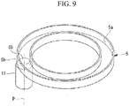
- a microscope 61 according to this embodiment differs from the microscope according to the first embodiment in that the cuvette 3 and the chamber 5 have an annular shape and in that the movable stage 7 supports the cuvette 3 so as to be rotatable about an axis parallel to the detection light axis P.
- the cuvette 3 is, for example, a micro plate formed by arranging, along a circumferential direction, a plurality of accommodation sections 3a in which the samples S are accommodated.
- This cuvette 3 has a transparent section 3b at the side wall section and at the bottom section for each of the accommodation sections 3a.
- the side wall section and the bottom section are formed of the transparent sections 3b all along the circumferential direction.
- the chamber 5 has the opening 5a, the inner diameter of which is smaller than the inner diameter of the cuvette 3 and the outer diameter of which is larger than the outer diameter of the cuvette 3.
- this chamber 5 has the transparent section 5b, one each on the illumination light axes Q of the illumination optical system 9 at the side wall section and on the detection light axis P of the immersion objective lens 11 at the bottom section.
- the side wall section and the bottom section may be formed of the transparent section 5b all along the circumferential direction.
- the illumination optical system 9 causes a laser beam to be incident via the transparent section 5b at the side wall section of the chamber 5.
- the cuvette 3 is rotated with the movable stage 7 about an axis parallel to the detection light axis P to place any one of the accommodation sections 3a on the detection light axis P.
- the laser beam emitted from the laser light source 15 in this state is guided by the optical fiber 17, is converted into a collimated beam by the convex lens 19A, is focused into a planar laser beam by the cylindrical lens 21A, and then passes through the transparent section 5b at the side wall section of the chamber 5.
- the laser beam that has entered the chamber 5 passes through the transparent section 3b at the side wall section of the cuvette 3 and enters the sample S. By doing so, a fluorescence image of the sample S in the accommodation section 3a disposed on the detection light axis P can be acquired.
- the cuvette 3 is rotated with the movable stage 7 about an axis parallel to the detection light axis P to place the next adjacent accommodation section 3a on the detection light axis P.
- the sample S in the next accommodation section 3a placed on the detection light axis P is also irradiated with a laser beam in the same manner to acquire a fluorescence image. Fluorescence images of the samples S accommodated in the accommodation sections 3a are acquired sequentially by switching in this manner so that the accommodation section 3a of the cuvette 3 is placed on the detection light axis P.
- the sample S to be placed on the detection light axis P can be selected merely by moving, with the movable stage 7, the cuvette 3 about an axis parallel to the detection light axis P. Therefore, images can be acquired sequentially with the camera 31 by causing the illumination optical system 9 to sequentially irradiate the sample S in each of the accommodation sections 3a with a laser beam and sequentially causing the immersion objective lens 11 to collect fluorescence from the sample S in each of the accommodation sections 3a. By doing so, images of a large number of samples S can be acquired in an efficient and fast manner.
- each of the cuvettes 3 be supported with the movable stage 7 so as to be movable about an axis parallel to the detection light axis P, thereby switching the cuvette 3 to be placed on the detection light axis P.
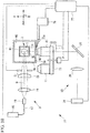
- a microscope 71 according to this embodiment differs from the microscopes according to the first to fourth embodiments in that the illumination optical system 9 is a single illumination system and causes a laser beam to pass through a side wall section of the chamber 5 and to enter a sample S, in that the immersion objective lens 11 collects fluorescence coming from the sample S via a side wall section of the chamber 5, and in that the movable stage 7 supports the cuvette 3 such that the cuvette 3 can be moved in the X, Y, and Z directions and rotated about a predetermined rotation axis orthogonal to the illumination light axis Q and the detection light axis P in the chamber 5 .
- the microscope 71 includes: the cuvette 3; the chamber 5; the movable stage 7; the illumination optical system 9; a plurality of the immersion objective lenses 11 having different magnifications; a revolver 73 for supporting the plurality of immersion objective lenses 11; the targeting section 12 for moving the immersion objective lenses 11 supported by the revolver 73 in a direction along the detection light axis P; the imaging optical system 13; a water replenishing device 75 for replenishing the liquid immersion solution W3; and a control device 77 for controlling the movable stage 7 and so forth.
- reference sign 79 denotes a drain tank.
- the cuvette 3 is a single storage container filled with the cuvette solution W1, and the sample S is immersed in the cuvette solution W1.
- the cuvette 3 has a transparent section (light transmitting section) 3b on each of all the side wall sections in the peripheral direction.
- the chamber 5 has transparent sections (light transmitting sections) 5b on two side wall sections adjacent to each other.
- the illumination optical system 9 includes: the laser light source 15; the optical fiber 17; a convex lens 19 for converting the laser beam guided by the optical fiber 17 into a collimated beam; a cylindrical lens 21 having the same structure as the cylindrical lenses 21A and 21B; and a variable diaphragm 81.
- variable diaphragm 81 is disposed between the cylindrical lens 21 and the transparent section 5b at the side wall section of the chamber 5.
- the thickness of the laser beam focused into a planar laser beam by the cylindrical lens 21 can be changed by changing the beam diameter of the laser beam using the variable diaphragm 81. This change is performed according to the immersion objective lens 11 inserted onto the optical path.
- a leading end section 18 of the optical fiber 17, the convex lens 19, the cylindrical lens 21, and the variable diaphragm 81 are disposed so as to face the transparent section 5b at one of the side wall sections of the chamber 5, and the laser beam emitted from laser light source 15 is made to enter the sample S via the transparent section 5b at the one side wall section of the chamber 5 and via the transparent section 3b at one of the side wall sections of the cuvettes 3.
- the immersion objective lenses 11 are disposed outside the chamber 5, with the detection light axes P thereof being orthogonal to the illumination light axis Q, so as to face the transparent section 5b at the other side wall section.
- the liquid immersion solution W3 such as pure water, is poured in the gap between the upper surface 11a of the lens at the most leading end of an immersion objective lens 11 and the transparent section 5b at the other side wall section of the chamber 5, and the liquid immersion solution W3 is held in the gap due to the surface tension.
- the revolver 73 can selectively place the plurality of immersion objective lenses 11 on the optical path of the fluorescence to be detected. By doing so, the immersion objective lens 11 to be used can be selected, for example, according to the purpose of observation.
- the water replenishing device 75 has a nozzle 75a at the leading end section thereof and, when switching the immersion objective lens 11, can replenish the liquid immersion solution W3 from the nozzle 75a into the gap between the upper surface 11a of the lens at the most leading end of the immersion objective lens 11 and the transparent section 5b at the side wall section of the chamber 5.
- the imaging optical system 13 includes the mirror 25, the image-forming lens 29 for forming an image of fluorescence reflected at the mirror 25, and the camera 31.
- the control device 77 controls movement of the cuvette 3 in the X, Y, and Z directions and rotation of the cuvette 3 about a predetermined rotation axis.
- the control device 77 controls the laser light source 15 and the camera 31 and controls: adjustment of the beam diameter of a laser beam with the variable diaphragm 81; switching among the immersion objective lenses 11 with the revolver 73; fine adjustment of the position in a direction along the detection light axis P of the immersion objective lens 11 with the targeting section 12; and replenishment of the liquid immersion solution W3 with the water replenishing device 75.
- control device 77 is used to cause the cuvette 3 in which the sample S and the cuvette solution W1 are accommodated to be supported by the movable stage 7 and to be immersed in the chamber solution W2 in the chamber 5, and then causes a laser beam to be produced from the laser light source 15.
- the laser beam emitted from the laser light source 15 is guided by the optical fiber 17, is converted into a collimated beam by the convex lens 19, is focused into a planar laser beam by the cylindrical lens 21, passes through the variable diaphragm 81, and enters the chamber 5 after having passed through the transparent section 5b at the side wall section of the chamber 5.
- the laser beam that has entered the chamber 5 enters the sample S from a direction orthogonal to the detection light axis P via the chamber solution W2, the transparent section 3b at the side wall section of the cuvette 3, and the cuvette solution W1.
- the fluorescent substance in the sample S is excited along the incident plane of the laser beam, thereby producing fluorescence.
- the fluorescence radiated in a direction along the detection light axis P is collected by the immersion objective lens 11 via the cuvette solution W1, the transparent section 3b at the side wall section of the cuvette 3, the chamber solution W2, the transparent section 5b at the side wall section of the chamber 5, and the liquid immersion solution W3.
- the fluorescence collected by the immersion objective lens 11 is reflected at the mirror 25 and is imaged by the image-forming lens 29 onto the imaging plane of the camera 31. By doing so, a cross-sectional image of the sample S orthogonal to the detection light axis P is obtained in the camera 31.
- a cross-sectional image of the sample S orthogonal to the detection light axis P is obtained in the camera 31.
- fluorescence produced in a wide area along the focal plane of the immersion objective lens 11 can be imaged with the camera 31 by collecting the fluorescence all at once with the immersion objective lens 11, thereby making it possible to acquire a clear fluorescence image of the observation region in the sample S.
- a superior three-dimensional stereoscopic image can be obtained by suppressing fluorescence fading.
- a superior image can be acquired over substantially the entire area of the sample S by driving the movable stage 7 using the control device 77 so as to rotate the cuvette 3 about a predetermined rotation axis orthogonal to the illumination light axis Q and detection light axis P, thereby inverting the orientation of the sample S relative to the immersion objective lens 11 so as to bring parts that have been far away from the immersion objective lens 11 of the sample S close to the immersion objective lens 11.
- the amount of the liquid immersion solution W3 disposed in the gap between the immersion objective lens 11 and the chamber 5 does not change (remains held as is due to the surface tension, irrespective of the focal point being finely adjusted), and therefore it is not necessary to prepare a large amount of the liquid immersion solution W3 or replenish the liquid immersion solution W3 so frequently, and furthermore the liquid immersion solution W3 can be prevented from running out.
- the shift in the focal position can be eliminated merely by finely adjusting the position in a direction along the detection light axis P of the immersion objective lens 11 using the targeting section 12.
- the invention may be applied to a light-field microscope.
- the illumination optical system 9 further include the cylindrical lens 43 having negative refractive power, in the same manner as in the second embodiment (refer to Fig. 4 ), and that the cylindrical lens 43 be placed between the cylindrical lens 21 and the chamber 5, thereby causing a laser beam having a thickness in a direction along the imaging light axis of the camera 31 to enter the sample S.
- the imaging optical system 13 include the microlens array 47 composed of the plurality of microlenses 48 for projecting an image onto the imaging plane of the camera 31 and the image-forming lens 29A (also refer to Fig. 4 ) for forming an image on the microlens array 47. By doing so, a plurality of items of image information having different parallaxes can be acquired all at once.
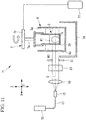
- a microscope 91 according to this embodiment differs from the microscopes according to the first to fifth embodiments in that the microscope 91 constitutes a luminescence microscope.
- the microscope 91 includes: the cuvette 3; the chamber 5; the movable stage 7; a dry objective lens (objective lens) 93 for collecting fluorescence emitted from a sample S; the targeting section 12 that can move the dry objective lens 93 in a direction along the detection light axis P thereof; the imaging optical system 13 for acquiring an image of the sample S on the basis of the fluorescence collected by the dry objective lens 93; and the control device 77 for controlling the movable stage 7 and so forth.
- a dry objective lens (objective lens) 93 for collecting fluorescence emitted from a sample S
- the targeting section 12 that can move the dry objective lens 93 in a direction along the detection light axis P thereof
- the imaging optical system 13 for acquiring an image of the sample S on the basis of the fluorescence collected by the dry objective lens 93
- the control device 77 for controlling the movable stage 7 and so forth.
- the cuvette 3 has, at the bottom section thereof, a transparent section (light transmitting section) 3b that can transmit fluorescence.
- the chamber 5 has, at the bottom section thereof, a transparent section (light transmitting section) 5b that can transmit fluorescence.
- the dry objective lens 93 is disposed outside the chamber 5 adjacently to the transparent section 5b at the bottom section and is placed face up so as to oppose the transparent section 5b.
- the dry objective lens 93 is disposed with a space, instead of the liquid immersion solution W3, interposed between the dry objective lens 93 itself and the transparent section 5b at the bottom section of the chamber 5.
- the imaging optical system 13 includes the image-forming lens 29 for forming an image of the fluorescence collected by the dry objective lens 93 and a camera 31.
- the cuvette 3 in which the sample S and the cuvette solution W1 are accommodated is supported by the movable stage 7, is immersed in the chamber solution W2 in the chamber 5, and is moved to the intended observation position.
- the fluorescence radiated in a direction along the detection light axis P is collected by the dry objective lens 93 via the cuvette solution W1, the transparent section 3b at the bottom section of the cuvette 3, the chamber solution W2, and the transparent section 5b at the bottom section of the chamber 5, and is then imaged by the image-forming lens 29 on the imaging plane of the camera 31.
- a cross-sectional image of the sample S orthogonal to the detection light axis P is obtained in the camera 31.
- the microscope 91 of this embodiment even though there occurs a shift in the focal position of the dry objective lens 93 depending on the refractive index profile in the sample S or a shift in the focal position of the dry objective lens 93 due to a slight difference between the index of refraction of the cuvette solution W1 and the index of refraction of the chamber solution W2 when the observation position of the sample S is changed by moving the cuvette 3 in the chamber 5, the shift in the focal position can be eliminated merely by finely adjusting the dry objective lens 93 in a direction along the detection light axis P by using the targeting section 12.
- equi-distant images can be obtained by performing slight fine adjustment when stacked images, which are acquired by driving the movable stage 7 in the Z direction at equal distances, are to be obtained, thereby making it possible to build a distortion-free three-dimensional image.
- the structure can be made all the more simple and inexpensive because no light sources or illumination optical systems are required.
- all of the cuvette solution W1, the chamber solution W2, the liquid immersion solution W3, the transparent section 3b of the cuvette 3, and the transparent section 5b of the chamber 5 have substantially the same index of refraction.
Landscapes
- Physics & Mathematics (AREA)
- Chemical & Material Sciences (AREA)
- Analytical Chemistry (AREA)
- General Physics & Mathematics (AREA)
- Optics & Photonics (AREA)
- Health & Medical Sciences (AREA)
- Biochemistry (AREA)
- Life Sciences & Earth Sciences (AREA)
- General Health & Medical Sciences (AREA)
- Immunology (AREA)
- Pathology (AREA)
- Oil, Petroleum & Natural Gas (AREA)
- Nuclear Medicine, Radiotherapy & Molecular Imaging (AREA)
- Engineering & Computer Science (AREA)
- Multimedia (AREA)
- Microscoopes, Condenser (AREA)
- Investigating, Analyzing Materials By Fluorescence Or Luminescence (AREA)
Applications Claiming Priority (2)
| Application Number | Priority Date | Filing Date | Title |
|---|---|---|---|
| JP2016160454 | 2016-08-18 | ||
| JP2017026640A JP6832735B2 (ja) | 2016-08-18 | 2017-02-16 | 顕微鏡 |
Publications (1)
| Publication Number | Publication Date |
|---|---|
| EP3293559A1 true EP3293559A1 (fr) | 2018-03-14 |
Family
ID=59655931
Family Applications (1)
| Application Number | Title | Priority Date | Filing Date |
|---|---|---|---|
| EP17186629.6A Withdrawn EP3293559A1 (fr) | 2016-08-18 | 2017-08-17 | Microscope |
Country Status (2)
| Country | Link |
|---|---|
| US (1) | US10310248B2 (fr) |
| EP (1) | EP3293559A1 (fr) |
Families Citing this family (18)
| Publication number | Priority date | Publication date | Assignee | Title |
|---|---|---|---|---|
| FR3031196B1 (fr) * | 2014-12-29 | 2017-01-13 | Karla Balaa | Dispositif pour realiser de la microscopie a feuille de lumiere |
| JP2018185456A (ja) * | 2017-04-27 | 2018-11-22 | オリンパス株式会社 | 顕微鏡 |
| DE102018203247A1 (de) | 2018-03-05 | 2019-09-05 | Leica Microsystems Cms Gmbh | Optische Vorrichtung, optisches Modul und Mikroskop zum Abtasten großer Proben |
| US20210239955A1 (en) * | 2018-06-08 | 2021-08-05 | The Board Of Trustees Of The Leland Stanford Junior University | Near infra-red light sheet microscopy through scattering tissues |
| DE102018126526A1 (de) * | 2018-10-24 | 2020-04-30 | Carl Zeiss Microscopy Gmbh | Immersionsmittelaufbringung mittels einer Strahldüse |
| DE102018126527A1 (de) | 2018-10-24 | 2020-04-30 | Carl Zeiss Microscopy Gmbh | Vorrichtung und Verfahren zum Aufbringen eines flüssigen Immersionsmittels in einen Spalt zwischen einem Mikroskopobjektiv und einer zu mikroskopierenden Probe |
| DE102018222271A1 (de) * | 2018-12-19 | 2020-06-25 | Carl Zeiss Microscopy Gmbh | Verfahren zum Betrieb einer Probenkammer für eine mikroskopische Bildgebung sowie Vorrichtung und Probenkammer |
| US20220026696A1 (en) * | 2018-12-21 | 2022-01-27 | Lavision Biotec Gmbh | Light sheet microscope with turreted lenses |
| DE102018222876A1 (de) * | 2018-12-21 | 2020-06-25 | Leica Microsystems Cms Gmbh | Mikroskop und Verfahren zur mikroskopischen Untersuchung großer Proben |
| WO2020126634A2 (fr) * | 2018-12-21 | 2020-06-25 | Lavision Biotec Gmbh | Microscope à feuille de lumière, équipé d'un contenant mobile |
| WO2021119201A1 (fr) | 2019-12-10 | 2021-06-17 | Enumerix, Inc. | Procédés et systèmes d'imagerie à nappe de lumière tridimensionnelle |
| EP4105642A4 (fr) * | 2020-02-12 | 2023-11-29 | MGI Tech Co., Ltd. | Système de formation d'image optique et système de détection de substance biochimique l'utilisant |
| KR20230004553A (ko) * | 2020-04-30 | 2023-01-06 | 루머스 리미티드 | 광학 샘플 특성화 |
| EP4211508B1 (fr) * | 2020-09-14 | 2025-11-26 | Singular Genomics Systems, Inc. | Procédés et systèmes d'imagerie multidimensionnelle |
| CN118696226A (zh) * | 2022-02-24 | 2024-09-24 | 加泰罗尼亚生物工程研究所基金会 | 用于测量生物样本的固有自发荧光的设备及其使用方法 |
| US20230304934A1 (en) * | 2022-03-23 | 2023-09-28 | The University Of North Carolina At Chapel Hill | Mirror based light sheet illumination system for light microscopy |
| US12581050B2 (en) * | 2022-11-23 | 2026-03-17 | 10X Genomics, Inc. | Optical assemblies for machine vision calibration |
| CN116735530A (zh) * | 2023-06-05 | 2023-09-12 | 福建师范大学 | 一种透明液体折射率、浓度测量仪及测量方法 |
Citations (4)
| Publication number | Priority date | Publication date | Assignee | Title |
|---|---|---|---|---|
| US20090086314A1 (en) * | 2006-05-31 | 2009-04-02 | Olympus Corporation | Biological specimen imaging method and biological specimen imaging apparatus |
| JP4443832B2 (ja) | 2001-05-11 | 2010-03-31 | エボテック・アーゲー | 化学的及び/または生物学的な試料の検査用装置 |
| WO2015184124A1 (fr) | 2014-05-30 | 2015-12-03 | The Board Of Trustees Of The Leland Stanford Junior University | Procédés et dispositifs pour l'imagerie de grands échantillons de tissus intacts |
| EP3125014A1 (fr) * | 2015-07-31 | 2017-02-01 | Olympus Corporation | Microscope inversé et système de microscope inversé |
Family Cites Families (8)
| Publication number | Priority date | Publication date | Assignee | Title |
|---|---|---|---|---|
| JP5216318B2 (ja) * | 2007-12-27 | 2013-06-19 | 株式会社日立ハイテクノロジーズ | 蛍光検出装置 |
| JP6169580B2 (ja) * | 2011-10-11 | 2017-07-26 | カール ツァイス マイクロスコピー ゲーエムベーハーCarl Zeiss Microscopy Gmbh | 顕微鏡、およびspim顕微鏡検査方法 |
| DE102012108158B4 (de) * | 2012-09-03 | 2016-03-17 | Johann Wolfgang Goethe-Universität | Kapillarzelle, Anordnung und Verfahren zur Aufnahme, zur Positionierung und zur Untersuchung einer mikroskopischen Probe |
| EP2801855B1 (fr) * | 2013-05-10 | 2019-07-17 | European Molecular Biology Laboratory | Module de microscope pour l'imagerie d'un échantillon |
| DE102013210269B8 (de) * | 2013-06-03 | 2015-01-29 | Laser Zentrum Hannover E.V. | Vorrichtung und Verfahren zur Untersuchung von Proben in einer Flüssigkeit |
| DE102013211426A1 (de) * | 2013-06-18 | 2014-12-18 | Leica Microsystems Cms Gmbh | Verfahren und optische Vorrichtung zum mikroskopischen Untersuchen einer Vielzahl von Proben |
| JP2018096703A (ja) * | 2016-12-08 | 2018-06-21 | オリンパス株式会社 | マイクロプレートおよび顕微鏡システム |
| JP2018128604A (ja) * | 2017-02-09 | 2018-08-16 | オリンパス株式会社 | 顕微鏡装置 |
-
2017
- 2017-08-16 US US15/678,854 patent/US10310248B2/en active Active
- 2017-08-17 EP EP17186629.6A patent/EP3293559A1/fr not_active Withdrawn
Patent Citations (4)
| Publication number | Priority date | Publication date | Assignee | Title |
|---|---|---|---|---|
| JP4443832B2 (ja) | 2001-05-11 | 2010-03-31 | エボテック・アーゲー | 化学的及び/または生物学的な試料の検査用装置 |
| US20090086314A1 (en) * | 2006-05-31 | 2009-04-02 | Olympus Corporation | Biological specimen imaging method and biological specimen imaging apparatus |
| WO2015184124A1 (fr) | 2014-05-30 | 2015-12-03 | The Board Of Trustees Of The Leland Stanford Junior University | Procédés et dispositifs pour l'imagerie de grands échantillons de tissus intacts |
| EP3125014A1 (fr) * | 2015-07-31 | 2017-02-01 | Olympus Corporation | Microscope inversé et système de microscope inversé |
Also Published As
| Publication number | Publication date |
|---|---|
| US10310248B2 (en) | 2019-06-04 |
| US20180052314A1 (en) | 2018-02-22 |
Similar Documents
| Publication | Publication Date | Title |
|---|---|---|
| US10310248B2 (en) | Microscope including a medium container containing an immersion medium in which a specimen container containing an immersion medium and a sample is immersed | |
| US10712547B2 (en) | Microscope, focusing unit, fluid holding unit, and optical unit | |
| US11327288B2 (en) | Method for generating an overview image using a large aperture objective | |
| US8254020B2 (en) | Objective-coupled selective plane illumination microscopy | |
| CA2509330C (fr) | Microscope ou le sens de l'observation est perpendiculaire au sens de l'eclairage | |
| JP6195922B2 (ja) | 顕微鏡 | |
| US20180164569A1 (en) | Microplate and microscope system | |
| US7982170B2 (en) | Microscope system | |
| US20180314047A1 (en) | Microscope | |
| EP3074807B1 (fr) | Agencement optique pour l'imagerie d'un échantillon | |
| JP6832735B2 (ja) | 顕微鏡 | |
| US20210072524A1 (en) | Optical system with a tilted illumination plane and method for illuminating a sample volume in an optical system with a tilted illumination plane | |
| US11287633B2 (en) | Apparatuses, systems and methods for solid immersion meniscus lenses | |
| US12320966B2 (en) | Method and system for multi-view episcopic selective plane illumination microscope | |
| US20200064608A1 (en) | Lightsheet microscope | |
| JP2019003027A (ja) | マイクロプレートおよび顕微鏡装置 | |
| US12326548B2 (en) | Confocal scanner, confocal scanner system, and confocal microscope system | |
| US20240402475A1 (en) | Imaging system and method | |
| HK1228014B (en) | Optical arrangement for imaging a sample |
Legal Events
| Date | Code | Title | Description |
|---|---|---|---|
| PUAI | Public reference made under article 153(3) epc to a published international application that has entered the european phase |
Free format text: ORIGINAL CODE: 0009012 |
|
| STAA | Information on the status of an ep patent application or granted ep patent |
Free format text: STATUS: THE APPLICATION HAS BEEN PUBLISHED |
|
| AK | Designated contracting states |
Kind code of ref document: A1 Designated state(s): AL AT BE BG CH CY CZ DE DK EE ES FI FR GB GR HR HU IE IS IT LI LT LU LV MC MK MT NL NO PL PT RO RS SE SI SK SM TR |
|
| AX | Request for extension of the european patent |
Extension state: BA ME |
|
| STAA | Information on the status of an ep patent application or granted ep patent |
Free format text: STATUS: REQUEST FOR EXAMINATION WAS MADE |
|
| 17P | Request for examination filed |
Effective date: 20180910 |
|
| RBV | Designated contracting states (corrected) |
Designated state(s): AL AT BE BG CH CY CZ DE DK EE ES FI FR GB GR HR HU IE IS IT LI LT LU LV MC MK MT NL NO PL PT RO RS SE SI SK SM TR |
|
| GRAP | Despatch of communication of intention to grant a patent |
Free format text: ORIGINAL CODE: EPIDOSNIGR1 |
|
| STAA | Information on the status of an ep patent application or granted ep patent |
Free format text: STATUS: GRANT OF PATENT IS INTENDED |
|
| INTG | Intention to grant announced |
Effective date: 20190322 |
|
| STAA | Information on the status of an ep patent application or granted ep patent |
Free format text: STATUS: THE APPLICATION IS DEEMED TO BE WITHDRAWN |
|
| 18D | Application deemed to be withdrawn |
Effective date: 20190802 |