EP3293596A1 - Ausrichtungssteuerungsverfahren für drohne - Google Patents
Ausrichtungssteuerungsverfahren für drohne Download PDFInfo
- Publication number
- EP3293596A1 EP3293596A1 EP17186080.2A EP17186080A EP3293596A1 EP 3293596 A1 EP3293596 A1 EP 3293596A1 EP 17186080 A EP17186080 A EP 17186080A EP 3293596 A1 EP3293596 A1 EP 3293596A1
- Authority
- EP
- European Patent Office
- Prior art keywords
- receiver
- drone
- phase
- wireless signal
- target device
- Prior art date
- Legal status (The legal status is an assumption and is not a legal conclusion. Google has not performed a legal analysis and makes no representation as to the accuracy of the status listed.)
- Withdrawn
Links
Images



Classifications
-
- G—PHYSICS
- G05—CONTROLLING; REGULATING
- G05D—SYSTEMS FOR CONTROLLING OR REGULATING NON-ELECTRIC VARIABLES
- G05D1/00—Control of position, course, altitude or attitude of land, water, air or space vehicles, e.g. using automatic pilots
- G05D1/0011—Control of position, course, altitude or attitude of land, water, air or space vehicles, e.g. using automatic pilots associated with a remote control arrangement
- G05D1/0033—Control of position, course, altitude or attitude of land, water, air or space vehicles, e.g. using automatic pilots associated with a remote control arrangement by having the operator tracking the vehicle either by direct line of sight or via one or more cameras located remotely from the vehicle
-
- G—PHYSICS
- G05—CONTROLLING; REGULATING
- G05D—SYSTEMS FOR CONTROLLING OR REGULATING NON-ELECTRIC VARIABLES
- G05D1/00—Control of position, course, altitude or attitude of land, water, air or space vehicles, e.g. using automatic pilots
- G05D1/12—Target-seeking control
-
- B—PERFORMING OPERATIONS; TRANSPORTING
- B64—AIRCRAFT; AVIATION; COSMONAUTICS
- B64U—UNMANNED AERIAL VEHICLES [UAV]; EQUIPMENT THEREFOR
- B64U10/00—Type of UAV
- B64U10/10—Rotorcrafts
- B64U10/13—Flying platforms
-
- G—PHYSICS
- G01—MEASURING; TESTING
- G01C—MEASURING DISTANCES, LEVELS OR BEARINGS; SURVEYING; NAVIGATION; GYROSCOPIC INSTRUMENTS; PHOTOGRAMMETRY OR VIDEOGRAMMETRY
- G01C21/00—Navigation; Navigational instruments not provided for in groups G01C1/00 - G01C19/00
- G01C21/10—Navigation; Navigational instruments not provided for in groups G01C1/00 - G01C19/00 by using measurements of speed or acceleration
- G01C21/12—Navigation; Navigational instruments not provided for in groups G01C1/00 - G01C19/00 by using measurements of speed or acceleration executed aboard the object being navigated; Dead reckoning
- G01C21/16—Navigation; Navigational instruments not provided for in groups G01C1/00 - G01C19/00 by using measurements of speed or acceleration executed aboard the object being navigated; Dead reckoning by integrating acceleration or speed, i.e. inertial navigation
- G01C21/165—Navigation; Navigational instruments not provided for in groups G01C1/00 - G01C19/00 by using measurements of speed or acceleration executed aboard the object being navigated; Dead reckoning by integrating acceleration or speed, i.e. inertial navigation combined with non-inertial navigation instruments
-
- G—PHYSICS
- G01—MEASURING; TESTING
- G01C—MEASURING DISTANCES, LEVELS OR BEARINGS; SURVEYING; NAVIGATION; GYROSCOPIC INSTRUMENTS; PHOTOGRAMMETRY OR VIDEOGRAMMETRY
- G01C21/00—Navigation; Navigational instruments not provided for in groups G01C1/00 - G01C19/00
- G01C21/10—Navigation; Navigational instruments not provided for in groups G01C1/00 - G01C19/00 by using measurements of speed or acceleration
- G01C21/12—Navigation; Navigational instruments not provided for in groups G01C1/00 - G01C19/00 by using measurements of speed or acceleration executed aboard the object being navigated; Dead reckoning
- G01C21/16—Navigation; Navigational instruments not provided for in groups G01C1/00 - G01C19/00 by using measurements of speed or acceleration executed aboard the object being navigated; Dead reckoning by integrating acceleration or speed, i.e. inertial navigation
- G01C21/18—Stabilised platforms, e.g. by gyroscope
-
- G—PHYSICS
- G01—MEASURING; TESTING
- G01S—RADIO DIRECTION-FINDING; RADIO NAVIGATION; DETERMINING DISTANCE OR VELOCITY BY USE OF RADIO WAVES; LOCATING OR PRESENCE-DETECTING BY USE OF THE REFLECTION OR RERADIATION OF RADIO WAVES; ANALOGOUS ARRANGEMENTS USING OTHER WAVES
- G01S5/00—Position-fixing by co-ordinating two or more direction or position line determinations; Position-fixing by co-ordinating two or more distance determinations
- G01S5/02—Position-fixing by co-ordinating two or more direction or position line determinations; Position-fixing by co-ordinating two or more distance determinations using radio waves
- G01S5/0247—Determining attitude
-
- G—PHYSICS
- G01—MEASURING; TESTING
- G01S—RADIO DIRECTION-FINDING; RADIO NAVIGATION; DETERMINING DISTANCE OR VELOCITY BY USE OF RADIO WAVES; LOCATING OR PRESENCE-DETECTING BY USE OF THE REFLECTION OR RERADIATION OF RADIO WAVES; ANALOGOUS ARRANGEMENTS USING OTHER WAVES
- G01S5/00—Position-fixing by co-ordinating two or more direction or position line determinations; Position-fixing by co-ordinating two or more distance determinations
- G01S5/02—Position-fixing by co-ordinating two or more direction or position line determinations; Position-fixing by co-ordinating two or more distance determinations using radio waves
- G01S5/06—Position of source determined by co-ordinating a plurality of position lines defined by path-difference measurements
-
- G—PHYSICS
- G05—CONTROLLING; REGULATING
- G05D—SYSTEMS FOR CONTROLLING OR REGULATING NON-ELECTRIC VARIABLES
- G05D1/00—Control of position, course, altitude or attitude of land, water, air or space vehicles, e.g. using automatic pilots
- G05D1/0011—Control of position, course, altitude or attitude of land, water, air or space vehicles, e.g. using automatic pilots associated with a remote control arrangement
- G05D1/0016—Control of position, course, altitude or attitude of land, water, air or space vehicles, e.g. using automatic pilots associated with a remote control arrangement characterised by the operator's input device
-
- G—PHYSICS
- G05—CONTROLLING; REGULATING
- G05D—SYSTEMS FOR CONTROLLING OR REGULATING NON-ELECTRIC VARIABLES
- G05D1/00—Control of position, course, altitude or attitude of land, water, air or space vehicles, e.g. using automatic pilots
- G05D1/0011—Control of position, course, altitude or attitude of land, water, air or space vehicles, e.g. using automatic pilots associated with a remote control arrangement
- G05D1/0022—Control of position, course, altitude or attitude of land, water, air or space vehicles, e.g. using automatic pilots associated with a remote control arrangement characterised by the communication link
-
- G—PHYSICS
- G05—CONTROLLING; REGULATING
- G05D—SYSTEMS FOR CONTROLLING OR REGULATING NON-ELECTRIC VARIABLES
- G05D1/00—Control of position, course, altitude or attitude of land, water, air or space vehicles, e.g. using automatic pilots
- G05D1/10—Simultaneous control of position or course in three dimensions
- G05D1/101—Simultaneous control of position or course in three dimensions specially adapted for aircraft
-
- G—PHYSICS
- G08—SIGNALLING
- G08C—TRANSMISSION SYSTEMS FOR MEASURED VALUES, CONTROL OR SIMILAR SIGNALS
- G08C17/00—Arrangements for transmitting signals characterised by the use of a wireless electrical link
- G08C17/02—Arrangements for transmitting signals characterised by the use of a wireless electrical link using a radio link
-
- B—PERFORMING OPERATIONS; TRANSPORTING
- B64—AIRCRAFT; AVIATION; COSMONAUTICS
- B64U—UNMANNED AERIAL VEHICLES [UAV]; EQUIPMENT THEREFOR
- B64U2101/00—UAVs specially adapted for particular uses or applications
- B64U2101/30—UAVs specially adapted for particular uses or applications for imaging, photography or videography
-
- B—PERFORMING OPERATIONS; TRANSPORTING
- B64—AIRCRAFT; AVIATION; COSMONAUTICS
- B64U—UNMANNED AERIAL VEHICLES [UAV]; EQUIPMENT THEREFOR
- B64U2201/00—UAVs characterised by their flight controls
- B64U2201/20—Remote controls
-
- G—PHYSICS
- G06—COMPUTING OR CALCULATING; COUNTING
- G06F—ELECTRIC DIGITAL DATA PROCESSING
- G06F3/00—Input arrangements for transferring data to be processed into a form capable of being handled by the computer; Output arrangements for transferring data from processing unit to output unit, e.g. interface arrangements
- G06F3/01—Input arrangements or combined input and output arrangements for interaction between user and computer
- G06F3/03—Arrangements for converting the position or the displacement of a member into a coded form
- G06F3/033—Pointing devices displaced or positioned by the user, e.g. mice, trackballs, pens or joysticks; Accessories therefor
- G06F3/0338—Pointing devices displaced or positioned by the user, e.g. mice, trackballs, pens or joysticks; Accessories therefor with detection of limited linear or angular displacement of an operating part of the device from a neutral position, e.g. isotonic or isometric joysticks
-
- G—PHYSICS
- G06—COMPUTING OR CALCULATING; COUNTING
- G06F—ELECTRIC DIGITAL DATA PROCESSING
- G06F3/00—Input arrangements for transferring data to be processed into a form capable of being handled by the computer; Output arrangements for transferring data from processing unit to output unit, e.g. interface arrangements
- G06F3/01—Input arrangements or combined input and output arrangements for interaction between user and computer
- G06F3/03—Arrangements for converting the position or the displacement of a member into a coded form
- G06F3/033—Pointing devices displaced or positioned by the user, e.g. mice, trackballs, pens or joysticks; Accessories therefor
- G06F3/0346—Pointing devices displaced or positioned by the user, e.g. mice, trackballs, pens or joysticks; Accessories therefor with detection of the device orientation or free movement in a three-dimensional [3D] space, e.g. 3D mice, 6-DOF [six degrees of freedom] pointers using gyroscopes, accelerometers or tilt-sensors
Definitions
- the present invention relates to a drone, especially to an orientation control method for drone.
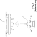
- Fig. 1 is a schematic view of a related-art drone system (also referred to unmanned aircraft system, UAS). As shown in Fig. 1 , the drone system 12 is generally controlled by joysticks 100, 102 arranged on a remote control 10. More particularly, a user may control the joysticks 100, 102 to move toward a specific direction or rotate to a specific orientation.
- UAS unmanned aircraft system
- the remote control 10 is operated with the drone system 12 as axial origin; this renders the remote control 10 failing to provide intuitional operation for user.
- the orientation of the drone system 12 is opposite to the orientation of user if the drone system 12 faces the user. Namely, the left side of the drone system 12 is the right side of the user.
- the user needs to operate the joystick 100 leftward to move the drone system 12 rightward with respect to user, this increasing the error possibility.
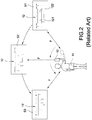
- Fig. 2 is a schematic view showing the orientation operation of a related-art drone system.
- researchers had proposed an orientation-based control method for the drone system 12. More particularly, user may hold the remote control 10 and wear a target device 14 to implement the orientation-based control method.
- the target device 14 continual sends ultrasonic signal to the drone system 12 such that the drone system 12 may determine a distance between the drone system 12 and the target device 14 (namely, the distance between the drone system 12 and the user) and an orientation of the drone system 12 with respect the target device 14 by using the ultrasonic signal.
- the drone system 12 moves toward the first position S1 based on the orientation operation.
- the drone system 12 moves toward the second position S2 based on the orientation operation.
- the drone system 12 moves toward the third position S3 based on the orientation operation.
- the drone system 12 keeps facing the target device 14 and keeps a trail distance F (for example 3 meters) with respect to the target device 14 during the movement thereof. Therefore, the user may control the movement of the drone system 12 more intuitionally (namely using the drone system 12 as axial origin).
- the drone system 12 mainly uses two built-in receivers 121 and 122 to receive the supersonic signals sent from the target device 14 and then determines the distance and orientation of the drone system 12 with respect to the target device 14 based on the supersonic signals.
- the receivers 121 and 122 receive the supersonic signals at the same time due to equal distance between the receivers 121 and 122 and the target device 14. If the drone system 12 does not face directly toward the target device 14, the receivers 121 and 122 receive the supersonic signals at difference time (for example, at 0.010 seconds and 0.013 seconds respectively).
- the supersonic signal is susceptible to interference to other signal. Due to the high directivity of the supersonic signal, the propagation of the supersonic signal will be influenced if obstacle (such as human body) is present between the drone system 12 and the target device 14.
- obstacle such as human body
- the orientation control method of the present invention uses at least three receivers to receive a set of wireless signals sent from a target device respectively and uses a phase detector to detect the phases of the wireless signals received by the at least three receivers. Afterward, the drone calculates a relative orientation of the drone with respect to the target device based on a phase difference between the wireless signals received by the at least three receivers and receives a directional signal sent from a remote control, thus controls a movement of the drone based on the relative orientation and the directional signal. Therefore, the drone can be correctly orientated the user-indicated direction.
- the present invention uses a plurality of receivers to respectively receive wireless signals sent from a single source and directly determines the orientation of the drone with respect to the target device, thus correctly orientate the drone toward the target device. Moreover, due to correct orientation of the drone, the drone can be precisely moved to user designated position when user instructs the drone to move and rotate, and then rotated to user designated orientation and direction.
- Fig. 3 is a schematic diagram of the drone system according to a first embodiment of the present invention.
- the present invention discloses an orientation control method (hereafter referred to the method) for drone system and the method can be used in the drone system 2 shown in Fig. 3 .
- the drone system 2 mainly comprises a drone 3 (such as steamboat, hot-air balloon, rotorcraft or airplane), a remote control 4 and a target device 5.
- a drone 3 such as steamboat, hot-air balloon, rotorcraft or airplane
- a remote control 4 such as steamboat, hot-air balloon, rotorcraft or airplane
- target device 5 such as a target device 5.
- user may perform orientation operation to the drone 3 with the remote control 4 and control the fly of the drone 3 with the target device 5 as axial origin.
- the drone 3 comprises a processor 31, a driving unit 32, a plurality of receivers (or transceivers) 33, a phase detector 34, a memory unit 35 and a camera 36.
- the processor 31 electrically connects with the driving unit 32, the receivers 33, the phase detector 34, the memory unit 35 and the camera 36.
- the driving unit 32 is used to control the movement (horizontal movement or vertical movement) and the rotation of the drone 3.
- the memory unit 35 is used to store data and the camera 36 is used to fetch image.
- the processor 31 is used to control the drone 3 by controlling the above units.
- the receivers 33 respectively receive wireless signals sent from the remote control 4 and the target device 5.
- the phase detector 34 is used to detect the phase difference between the wireless signals received by the receivers 33.
- the drone 3 first uses the processor 31 to calculate a phase difference between the wireless signals received by the receivers 33 and then determines the orientation of the drone 3 with respect to the target device 5 (generally worn by user or by the object to be photo-taken by the camera 36). The drone 3 can then be orientated to facilitate the control of the drone 3 through the remote control 4 for user.
- the remote control 4 comprises a processing module 41, a human-machine interface 42, a transceiver module (or receiver module) 43, a geomagnetic meter 44, a gyroscope 45 and an acceleration meter 46, where the processing module 41 electrically connects with the human-machine interface 42, the transceiver module 43, the geomagnetic meter 44, the gyroscope 45 and the acceleration meter 46.
- the user holds the remote control 4 to directly perform orientation operation.
- the remote control 4 may obtain the azimuth angle thereof (for example, north-east or south-west) by sensing the geomagnetic change through using the geomagnetic meter 44, obtain the elevation angle thereof through using the gyroscope 45 (for example, a three-axis gyroscope) and obtain a moving acceleration thereof through using the acceleration meter 46 (for example, a three-axis acceleration meter).
- the azimuth angle thereof for example, north-east or south-west
- the geomagnetic meter 44 obtain the elevation angle thereof through using the gyroscope 45 (for example, a three-axis gyroscope) and obtain a moving acceleration thereof through using the acceleration meter 46 (for example, a three-axis acceleration meter).
- the processing module 41 of the remote control 4 performs calculation to generate an orientation azimuth angle based on the azimuth angle, generate an orientation elevation angle based on the elevation angle and/or the moving acceleration.
- the processing module 41 generates a directional signal based on the directional azimuth angle and the directional elevation angle.
- the transceiver module 43 sends the directional signal outward.
- the human-machine interface 42 receives operations of user and modifies the directional signal based on the contents in the received operations of user (such as clockwise rotating the drone 3 by 20 degree or approaching the user by 10 centimeters and so on), thus controlling the drone 3 for movement or rotation with corresponding angle.
- the human-machine interface 42 may also include signal indicator such as display screen, loud speaker, indication lamp to feedback information of the drone 3 for user.
- the processing module 41 generates the directional signal based on the sensed information from the geomagnetic meter 44, the gyroscope 45 and the acceleration meter 46 and the operation information from the human-machine interface 42. Moreover, the transceiver module 43 sends the directional signal outward. The processing module 41 further controls the processing module 41 to receive related information for the drone 3 sent from external devices and display/indicate the related information through the human-machine interface 42.
- the casing of the remote control 4 is fit for single hand operation and for holding by user.
- the user can smoothly operate the remote control 4 to point to the desired orientation and more intuitionally control the drone 3 to move to the destined direction/orientation or position.
- the target device 5 mainly includes a processing unit 51 and a transceiver unit 52 electrically connected with the processing unit 51.
- the target device 5 is worn by user, where the user is a user holding the remote control 4 or an object to be photo-taken by the drone 3 (for example, the drone 3 conducting a selfie mode to take photo for user).
- the target device 5 uses the processing unit 51 to calculate the position information thereof (namely, the position information of user) and generate a wireless signal based on the position information.
- the wireless signal is sent by the transceiver unit 52.
- the drone 3 identifies the position of the target device 5 by the received wireless signal and then performs positioning (orientating), movement, and rotation with the target device 5 as axial origin.
- the receivers 33, the transceiver module 43, and the transceiver unit 52 are wireless radio wave receivers (transceivers), the directional signal and the wireless signal are wireless radio wave signals, where the wireless signal sent by the target device 5 has a wavelength of ⁇ .
- the receivers 33 include at least a first receiver 331, a second receiver 332 and a third receiver 333.
- the drone 3 may directly calculate the orientation of the drone 3 with respect to the target device 5 based on phase differences of wireless signals received by the three receivers 33. Therefore, the drone 3 and the target device 5 can be dispensed with the GPS device and need not receive external positioning signals by bluetooth or other wireless transmission scheme. The cost of the drone system 2 is reduced and the positioning (orientating) accuracy of the drone 3 is enhanced.
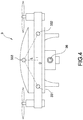
- Fig. 4 shows a side view of the drone according to the first embodiment of the present invention.
- the drone 3 of the present invention has at least three receivers 33 therein to perform positioning (orientating) for the drone 3 without using additional positioning device (such as GPS device).
- additional positioning device such as GPS device.
- the distance between the first receiver 331 and the second receiver 332 is D (for example but not limited to 30 cm)
- the distance between the midpoint (midpoint 334 shown in Fig. 9 ) of the first receiver 331 and the second receiver 332 and the third receiver 333 is L.
- the receivers 33 are arranged at vertices of an isosceles triangle (namely, the distance between the first receiver 331 and the third receiver 333 is equal to the distance between the second receiver 332 and the third receiver 333) or arranged at vertices of an equilateral triangle, but the scope of the present invention is not limited to above examples.
- the wavelength ⁇ of the wireless signal is equal to or slightly larger than two times of the distance D between the first receiver 331 and the second receiver 332, namely, ⁇ 2D.
- the present invention performs positioning (orientating) by using the phase difference of the received wireless signals.
- the phase difference of the wireless signals received by the first receiver 331 and the second receiver 332 is zero and when the phase difference of the wireless signal corresponding to the midpoint and the wireless signal received by the third receiver 333is also zero, it means that the drone 3 orientates toward (faces) the target device 5 directly.
- the camera 36 arranged on the front face of the drone 3 also orientates toward (faces) the target device 5 directly (namely faces the user directly) when the drone 3 orientates toward (faces) the target device 5 directly. Therefore, user can control the drone 3 for selfie.
- the method described in various embodiments of the present invention can be implemented by the drone system 2 shown in Fig. 2 .
- the memory unit 35 of the drone 3 further stores a computer program including computer-executable code.
- the processor 31 can control the drone 3 to perform the steps of the invention when the processor 31 executes the computer program.
- Fig. 5 is an orientation control flowchart according to the first embodiment of the present invention.
- the target device 5 continually sends the wireless signal after the drone system 2 is activated (turned on), and the three receivers 33 respectively receive the wireless signals sent from the target device 5. More particularly, the target device 5 continually sends the wireless signal through broadcasting.
- the drone 3 uses the phase detector 34 to detect the phases of wireless signals received by the three receivers 33 and the processor 31 calculates a phase differences based on the phases detected by the phase detector 34.
- the phase differences include a first phase difference between the wireless signals received by the first receiver 331 and the second receiver 332 and a second phase difference between the wireless signal corresponding to the midpoint 334 (for example the wireless signal corresponding to the midpoint 334 may be obtained by interpolating the wireless signals received by the first receiver 331 and the second receiver 332) and the signals received at the third receiver 333.
- the processor 31 calculates a relative orientation of the drone 3 with respect to the target device 5 in step S 14.
- the relative orientation comprises an included angle between a plane connecting the first receiver 331 and the second receiver 332 and the target device 5, and an included angle between a plane connecting the midpoint 334 and the third receiver 333 and the target device 5.
- the drone 3 uses one of or all of the three receivers 33 to receive the directional signal from the remote control 4.
- the processor 31 of the drone 3 controls the movement of the drone 3 based on the relative orientation and the directional signal.
- the processor 31 calculates a relative orientation of the drone 3 with respect to the target device 5 based on the above-mentioned phase differences, and automatically controls the movement (or rotation) of the drone 3 based on the calculated relative orientation such that the drone 3 orientates toward (faces) the target device 5 directly. If the user operates the remote control 4 to send the directional signal and the directional signal includes signal controlling the drone 3 to rotate, the processor 31 fine tunes the direction of the drone 3 based on the directional signal.
- the drone 3 mainly provides selfie function. Therefore, the above mentioned movement or rotation renders the drone 3 to move or rotate to orientate toward (face) the target device 5 directly or renders the camera (not shown in Fig. 4 ) of the drone 3 to move or rotate to orientate toward (face) the target device 5 directly.
- the processor 31 determines whether the three receivers 33 stop receiving the wireless signals (step S18), namely whether the target device 5 is turned off, or the communication between the drone 3 and the target device 5/the remote control 4 is terminated. If the three receivers 33 stop receiving the wireless signal, the processor 31 ends the orientation control method. If the three receivers 33 continually receive the wireless signals, the processor 31 repeatedly executes step S10 to step S16 to continually orientate the drone 3 and control the movement of the drone 3.
- Fig. 6A and 6B show the phase differences according to the first embodiment and the second embodiment respectively.
- the distance d1 between the first receiver 331 and the target device 5 and the distance d2 between the second receiver 332 and the target device 5 are different. Therefore, the wireless signal sent by the target device 5 and received by the first receiver 331 and the wireless signal sent by the target device 5 and received by the second receiver 332 have different phases.
- the phase of the wireless signal received by the first receiver 331 is 4 4 ⁇
- the phase of the wireless signal received by the second receiver 332 is 6 4 ⁇ , which have phase difference of 2 4 ⁇ .
- the phase difference between the two wireless signals can be optimally identified if the wavelength ⁇ of the wireless signal is equal to or slightly large than two times of the distance D between the first receiver 331 and the second receiver 332.
- the wavelength ⁇ of the wireless signal is preset to be two times of the distance D.
- the directional signal has arbitrary wavelength and needs not to be equal to or slightly large than two times of the distance D, because the drone 3 is not orientated with reference to the directional signal sent by the remote control 4.
- the processor 31 may apply the first formula below to calculate the relative orientation of the drone 3 with respect to the target device 5 once the processor 31 calculates the phase difference between the wireless signals received by the first receiver 331 and the second receiver 332.
- ⁇ cos ⁇ 1 ⁇ 2 ⁇ ⁇ 1 ⁇ 2 ⁇ D
- ⁇ is the included angle between the plane ( d 1 d 2 ) connecting the first receiver 331 and second receiver 332 and the target device 5
- ⁇ 2 is the phase of the wireless signal received by the second receiver 332 (for example, above mentioned phase 6 4 ⁇ )
- ⁇ 1 is the phase of the wireless signal received by the first receiver 331 (for example, above mentioned phase 4 4 ⁇ )
- ⁇ is the wavelength of the wireless signal
- D is the distance between the first receiver 331 and the second receiver 332, where ⁇ 2D.
- the processor 31 may control the drone 3 to rotate based on the above calculation result such that the phase difference between the phase ⁇ 1 of the wireless signal received by the first receiver 331 and the phase ⁇ 2 of the wireless signal received by the second receiver 332 is zero.
- the plane ( d 1 d 2 ) connecting the first receiver 331 and second receiver 332 orientates directly to the target device 5 if the processor 31 controls the drone 3 to rotate to null the phase difference to zero.
- the drone 3 does not orientate directly to the target device 5 if the distance d3 between the third receiver 333 and the target device 5 is either different with the distance d1 between the first receiver 331 and the target device 5 or different with the distance d2 between the second receiver 332 and the target device 5.
- the signal corresponding to the midpoint 334 is compared with the signal received at the third receiver 333.
- the phase of the wireless signal received by the third receiver 333 is 7.9 2 ⁇
- the phase of the wireless signal corresponding to the midpoint 334 is 5 2 ⁇
- the difference thereof is 2.9 2 ⁇ .
- the processor 31 may apply the second formula below to calculate the another relative orientation component of the drone 3 to the target device 5 once the processor 31 calculates the phase difference between the wireless signal of the midpoint 334 and the wireless signal received by the third receiver 333, namely, applying the second formula to execute the step S14 shown in Fig. 5 .
- ⁇ cos ⁇ 1 ⁇ 3 ⁇ ⁇ 1 + ⁇ 2 2 ⁇ 2 ⁇ L
- ⁇ is the included angle between the plane ( d 0 d 3 ) connecting the midpoint 334 and the third receiver 333 and the target device 5
- ⁇ 2 is the phase of the wireless signal received by the second receiver 332
- ⁇ 3 is the phase of the wireless signal received by the third receiver 333
- ⁇ is the wavelength of the wireless signal
- L is the distance between the midpoint and the third receiver 333.
- the orientation of the drone 3 with respect to the target device 5 can only be calibrated on two dimensional spaces (namely alone a plane).
- the number of the receivers is equal to or more than three
- the orientation of the drone 3 with respect to the target device can be calibrated on three dimensional spaces, thus more accurately orientate the drone 3. Therefore, in the present invention, the numbers of the receivers is at least three.
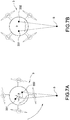
- Figs. 7A and 7B are drawings showing the movement of the drone according to the first embodiment and the second embodiment.
- the drone 3 of the invention comprises at least three receivers 33.
- the drone according to the first embodiment and the second embodiment in Figs. 7A and 7B are exemplified with the first receiver 331 and the second receiver 332 for describing the movement thereof.
- the drone 3 does not orientate directly toward the target device 5; therefore, the distance between the first receiver 331 and the target device 5 and the distance between the second receiver 332 and the target device 5 are different. Namely, the phase of the wireless signal received by the first receiver 331 is different with the phase of the wireless signal received by the second receiver 332. Moreover, an included angle ⁇ is present between the plane ( d 1 d 2 ) connecting the first receiver 331 and second receiver 332 and the target device 5.
- the processor 31 of the drone 3 may control the rotation of the drone 3 (such as counterclockwise rotation in Fig. 7A ) based on the phase difference between the wireless signals received by the first receiver 331 and the second receiver 332.
- the wireless signals received by the first receiver 331 and the second receiver 332 have the same phase. It means that the drone 3 already orientates toward the target device 5 and the orientation of the drone 3 is finished.
- the above-mentioned orientation way may also be applied to the midpoint 334 and the third receiver 333, the detailed description thereof is omitted here for brevity.
- the user may effectively control the drone 3 for selfie, or control the drone 3 to move/rotate alone designated direction such that the drone 3 can be orientated to the direction designated by user.
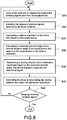
- Fig. 8 is an orientation control flowchart according to the second embodiment of the present invention, which is similar to the flowchart in Fig. 5 .
- the drone 3 also uses the three receivers to respectively receive wireless signals sent from the target device 5 (step S30), detects the phases of the wireless signals received by the three receivers with the phase detector 34 (step S32), and calculates a relative orientation of the drone 3 with respect to the target device 5 based on phase difference of the phases detected by the phase detector 34 (step S34).
- step S36 the processor 31 further calculates a horizontal azimuth angle and a vertical elevation angle of the target device 5 with respect to the drone 3 based on the relative orientation calculated in step S34 (which will be detailed later). Moreover, the processor 31 determines a moving direction and a destination coordinate based on the horizontal azimuth angle, the vertical elevation angle and the directional signal sent from the remote control 4 (step S38). Finally, the processor 31 controls the drone 3 to move along the moving direction and reach the destination coordinate (step S40) to comply with the directional operation. Therefore, the drone 3 keeps orientating with the target device 5 as axial origin and is moved based on the directional operation of user, thus the drone 3, the remote control 4 and the target device 5 have effective interaction therebetween.
- step S40 the processor 31 determines whether the wireless signals are not received in step S42, namely, whether the receivers 33 stop receiving the wireless signals.
- the processor 31 ends the orientation control method if the wireless signal is not received.
- the processor 31 repeatedly executes step S30 to step S40 to continually orientate the drone 3 and control the movement of the drone 3 if the wireless signals are continually received.
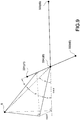
- this figure shows the relative positions of elements in the first embodiment.
- the processor 31 calculates the included angle ⁇ between the plane ( d 1 d 2 ) connecting the first receiver 331 and second receiver 332 and the target device 5 and the included angle ⁇ between the plane ( d 0 d 3 ) connecting the midpoint 334 and the third receiver 333 and the target device 5 in step S14 of Fig. 5 and in step S34 of Fig. 8 .
- the processor 31 calculates a horizontal azimuth angle A and a vertical elevation angle B of the target device 5 with respect to the drone 3 according to the following third formula and the fourth formula.
- A tan ⁇ 1 2 L ⁇ 2 ⁇ ⁇ 1 D 2 ⁇ 3 ⁇ ⁇ 1 ⁇ ⁇ 2
- A is the horizontal azimuth angle
- D is the distance between the first receiver 331 and the second receiver 332
- L is the distance between the midpoint 334 and the third receiver 333
- ⁇ 1 is the phase of the wireless signal received by the first receiver 331
- ⁇ 2 is the phase of the wireless signal received by the second receiver 332
- ⁇ 3 is the phase of the wireless signal received by the third receiver 333.
- cos A cos ⁇ cos ⁇ .
- the value of cos ⁇ and cos ⁇ can be obtained by above orientation calculation, therefore, the fourth formula can be derived as above.
- B cos ⁇ 1 ⁇ 2 ⁇ ⁇ 1 ⁇ 2 ⁇ D 2 + 2 ⁇ 3 ⁇ ⁇ 1 ⁇ ⁇ 2 ⁇ 4 ⁇ L 2
- B is the vertical elevation angle
- D is the distance between the first receiver 331 and the second receiver 332
- L is the distance between the midpoint 334 and the third receiver 333
- ⁇ 1 is the phase of the wireless signal received by the first receiver 331
- ⁇ 2 is the phase of the wireless signal received by the second receiver 332
- ⁇ 3 is the phase of the wireless signal received by the third receiver 333
- ⁇ is the is the wavelength of the wireless signal.
- the processor 31 can precisely calculate the relative position (orientation) of the drone 3 with respect to the target device 5 without using additional positioning device (such as GPS device), thus move the drone 3 with respect to user's directional operation.
- the processor 31 determines the moving direction and the destination coordinate based on the horizontal azimuth angle, the vertical elevation angle and the directional signal sent from the remote control 4.
- the directional signal includes a directional azimuth angle and a directional elevation angle generated by the remote control 4 after receiving the directional operation from user.
- the remote control 4 mainly uses the geomagnetic meter 44 to sense the geomagnetic change and generate the current azimuth angle for the remote control 4.
- the remote control 4 obtains the elevation angle thereof through using the gyroscope 45 and obtains a moving acceleration thereof through using the acceleration meter 46.
- the remote control 4 uses the processing module 41 therein to calculate the directional azimuth angle based on the azimuth angle and to calculate the directional elevation angle based on the elevation angle and/or the moving acceleration.
- the remote control 4 generates the directional signal based on the directional azimuth angle and the directional elevation angle and then sends the directional signal through the transceiver module 43 therein.
- the processor 31 receives the directional signal from the remote control 4.
- the processor 31 calculates the moving direction and the destination coordinate for the drone 3 based on an azimuth angle difference between the directional azimuth angle and the horizontal azimuth angle A and an elevation angle difference between the directional elevation angle and the vertical elevation angle B. Therefore, the drone 3 can be orientated according to the wireless signals sent from the target device 5 without needing GPS device.
- the drone 3 can be moved according to the directional signal sent from the remote control 4 to achieve precise interaction between user and the object to be photo-taken.
Landscapes
- Engineering & Computer Science (AREA)
- Remote Sensing (AREA)
- Radar, Positioning & Navigation (AREA)
- Physics & Mathematics (AREA)
- General Physics & Mathematics (AREA)
- Aviation & Aerospace Engineering (AREA)
- Automation & Control Theory (AREA)
- Mechanical Engineering (AREA)
- Computing Systems (AREA)
- Mathematical Physics (AREA)
- Theoretical Computer Science (AREA)
- Computer Networks & Wireless Communication (AREA)
- Control Of Position, Course, Altitude, Or Attitude Of Moving Bodies (AREA)
- Position Fixing By Use Of Radio Waves (AREA)
Applications Claiming Priority (1)
| Application Number | Priority Date | Filing Date | Title |
|---|---|---|---|
| TW105129173A TWI589905B (zh) | 2016-09-08 | 2016-09-08 | 飛行器的定位控制方法 |
Publications (1)
| Publication Number | Publication Date |
|---|---|
| EP3293596A1 true EP3293596A1 (de) | 2018-03-14 |
Family
ID=59655902
Family Applications (1)
| Application Number | Title | Priority Date | Filing Date |
|---|---|---|---|
| EP17186080.2A Withdrawn EP3293596A1 (de) | 2016-09-08 | 2017-08-14 | Ausrichtungssteuerungsverfahren für drohne |
Country Status (7)
| Country | Link |
|---|---|
| US (1) | US20180067503A1 (de) |
| EP (1) | EP3293596A1 (de) |
| JP (1) | JP2018040786A (de) |
| CN (1) | CN107807347A (de) |
| AU (1) | AU2017213533A1 (de) |
| CA (1) | CA2975671A1 (de) |
| TW (1) | TWI589905B (de) |
Families Citing this family (14)
| Publication number | Priority date | Publication date | Assignee | Title |
|---|---|---|---|---|
| JP2019182131A (ja) * | 2018-04-06 | 2019-10-24 | 日本電信電話株式会社 | 飛行制御装置、方法、及びプログラム |
| US20190324447A1 (en) * | 2018-04-24 | 2019-10-24 | Kevin Michael Ryan | Intuitive Controller Device for UAV |
| CN108680941B (zh) * | 2018-04-27 | 2020-06-30 | 东南大学 | 一种基于单站点的飞行器定位系统及方法 |
| CN110825121B (zh) | 2018-08-08 | 2023-02-17 | 纬创资通股份有限公司 | 控制装置与无人机控制方法 |
| TWI725497B (zh) * | 2018-08-08 | 2021-04-21 | 緯創資通股份有限公司 | 控制裝置與無人機控制方法 |
| CN109100684A (zh) * | 2018-08-14 | 2018-12-28 | 深圳市烽焌信息科技有限公司 | 一种无人机的寻找方法 |
| CN109309709B (zh) * | 2018-08-22 | 2021-08-10 | 北京臻迪科技股份有限公司 | 一种可远端控制无人装置的控制方法 |
| CN109343561B (zh) * | 2018-08-22 | 2022-05-13 | 臻迪科技股份有限公司 | 用以在电子装置显示与操作无人装置的操作方法 |
| CN109682332A (zh) * | 2019-01-29 | 2019-04-26 | 重庆固力建筑工程质量检测有限公司 | 一种电磁波自动测厚装置 |
| CN109671329B (zh) * | 2019-02-18 | 2020-12-08 | 成都众志天成科技有限公司 | 无线电测向模拟系统及方法 |
| CN110031801B (zh) * | 2019-05-16 | 2023-04-28 | 武汉大学 | 一种高速临近空间飞行器的探测方法及系统 |
| CN111131261A (zh) * | 2019-12-26 | 2020-05-08 | 苏州光之翼智能科技有限公司 | 一种警用无人机训练量化方法 |
| CN112799428B (zh) * | 2020-12-31 | 2024-10-18 | 广州极飞科技股份有限公司 | 控制方法、装置、被控设备及可读存储介质 |
| CN118671766A (zh) * | 2024-07-17 | 2024-09-20 | 成都睿沿芯创科技有限公司 | 雷达装置和定位方法 |
Citations (3)
| Publication number | Priority date | Publication date | Assignee | Title |
|---|---|---|---|---|
| US20130173088A1 (en) * | 2012-01-04 | 2013-07-04 | Parrot | Method for the intuitive piloting of a drone by means of a remote control |
| US20150153436A1 (en) * | 2013-12-03 | 2015-06-04 | The Boeing Company | Systems and methods of transmitter location detection |
| CN105182289A (zh) * | 2014-06-19 | 2015-12-23 | 中兴通讯股份有限公司 | 一种定位方法和设备 |
Family Cites Families (9)
| Publication number | Priority date | Publication date | Assignee | Title |
|---|---|---|---|---|
| JPS61284680A (ja) * | 1985-06-12 | 1986-12-15 | Toshiba Corp | 方位測定装置 |
| JP2001004731A (ja) * | 1999-06-17 | 2001-01-12 | Japan Science & Technology Corp | 広帯域干渉計 |
| JP5633900B2 (ja) * | 2010-05-18 | 2014-12-03 | 三井造船株式会社 | 部分放電標定装置および部分放電標定方法 |
| CN103138055A (zh) * | 2011-12-05 | 2013-06-05 | 深圳市金溢科技有限公司 | 比相无线定位天线及其系统、使用比相无线定位的方法 |
| CN104103095B (zh) * | 2013-04-11 | 2017-02-08 | 深圳市金溢科技股份有限公司 | 定位方法、装置及系统 |
| US10353049B2 (en) * | 2013-06-13 | 2019-07-16 | Basf Se | Detector for optically detecting an orientation of at least one object |
| CN104330769B (zh) * | 2013-07-22 | 2017-02-08 | 深圳市金溢科技股份有限公司 | 定位方法、通信控制方法、装置及系统 |
| US9678506B2 (en) * | 2014-06-19 | 2017-06-13 | Skydio, Inc. | Magic wand interface and other user interaction paradigms for a flying digital assistant |
| US9174733B1 (en) * | 2014-08-28 | 2015-11-03 | Google Inc. | Payload-release device and operation thereof |
-
2016
- 2016-09-08 TW TW105129173A patent/TWI589905B/zh not_active IP Right Cessation
-
2017
- 2017-05-09 CN CN201710320142.XA patent/CN107807347A/zh active Pending
- 2017-06-01 JP JP2017108995A patent/JP2018040786A/ja active Pending
- 2017-08-07 US US15/670,990 patent/US20180067503A1/en not_active Abandoned
- 2017-08-09 CA CA2975671A patent/CA2975671A1/en not_active Abandoned
- 2017-08-11 AU AU2017213533A patent/AU2017213533A1/en not_active Abandoned
- 2017-08-14 EP EP17186080.2A patent/EP3293596A1/de not_active Withdrawn
Patent Citations (3)
| Publication number | Priority date | Publication date | Assignee | Title |
|---|---|---|---|---|
| US20130173088A1 (en) * | 2012-01-04 | 2013-07-04 | Parrot | Method for the intuitive piloting of a drone by means of a remote control |
| US20150153436A1 (en) * | 2013-12-03 | 2015-06-04 | The Boeing Company | Systems and methods of transmitter location detection |
| CN105182289A (zh) * | 2014-06-19 | 2015-12-23 | 中兴通讯股份有限公司 | 一种定位方法和设备 |
Also Published As
| Publication number | Publication date |
|---|---|
| AU2017213533A1 (en) | 2018-03-22 |
| TW201809716A (zh) | 2018-03-16 |
| CN107807347A (zh) | 2018-03-16 |
| JP2018040786A (ja) | 2018-03-15 |
| CA2975671A1 (en) | 2018-03-08 |
| US20180067503A1 (en) | 2018-03-08 |
| TWI589905B (zh) | 2017-07-01 |
Similar Documents
| Publication | Publication Date | Title |
|---|---|---|
| EP3293596A1 (de) | Ausrichtungssteuerungsverfahren für drohne | |
| US11242953B2 (en) | Calibration for image stabilization mechanism | |
| US11009596B2 (en) | Storage medium location detection system and program | |
| JP5032887B2 (ja) | ポインター移動方法及び記録媒体 | |
| US8818420B2 (en) | Rotation-tolerant devices and schemes for pedestrian-dead-reckoning (PDR) location determination | |
| US20190163198A1 (en) | Radar aided visual inertial odometry initialization | |
| US8060256B2 (en) | Apparatus, method, and medium for localizing moving robot and transmitter | |
| EP3252558A1 (de) | Verfahren für folgende fernsteuerung für flugzeug | |
| TW201734686A (zh) | 多軸控制器 | |
| KR20180075191A (ko) | 무인 이동체를 제어하기 위한 방법 및 전자 장치 | |
| CN107632613A (zh) | 控制全向无人机中的天线方位角定向的系统和设备 | |
| KR20180031188A (ko) | 무선 전력 송신기 및 그 제어 방법 | |
| WO2016191875A1 (en) | Device and method for controlling a plurality of targeted devices | |
| CN104620189A (zh) | 具有微机电系统运动传感器的移动设备硬件姿态检测实现 | |
| CN107004961A (zh) | 二维天线系统、用于定位目标的方法和设备 | |
| US11662817B2 (en) | Method for controlling gimbal by somatosensory controller, gimbal, somatosensory controller, and system | |
| KR20200084199A (ko) | 무인 비행체를 이용한 신호원의 위치정보 확인 방법 및 장치 | |
| WO2019138466A1 (ja) | 無人航空機制御システム、無人航空機制御方法、及びプログラム | |
| US20190346268A1 (en) | Direction-finding chip, direction-finding method and beacon | |
| JP2021184621A (ja) | 飛行体およびプログラム | |
| US9976857B2 (en) | Apparatus for providing an azimuth angle | |
| JP2014153117A (ja) | 移動体の向きを示す情報を取得するシステム及び方法 | |
| JP2025178571A (ja) | 移動体制御装置及び移動体制御方法 | |
| Attaluri et al. | Reducing Cognitive Load in Remote Navigation through Adaptive Heading Mapping | |
| JPS63296502A (ja) | アンテナ指向システム |
Legal Events
| Date | Code | Title | Description |
|---|---|---|---|
| PUAI | Public reference made under article 153(3) epc to a published international application that has entered the european phase |
Free format text: ORIGINAL CODE: 0009012 |
|
| STAA | Information on the status of an ep patent application or granted ep patent |
Free format text: STATUS: THE APPLICATION HAS BEEN PUBLISHED |
|
| AK | Designated contracting states |
Kind code of ref document: A1 Designated state(s): AL AT BE BG CH CY CZ DE DK EE ES FI FR GB GR HR HU IE IS IT LI LT LU LV MC MK MT NL NO PL PT RO RS SE SI SK SM TR |
|
| AX | Request for extension of the european patent |
Extension state: BA ME |
|
| STAA | Information on the status of an ep patent application or granted ep patent |
Free format text: STATUS: THE APPLICATION IS DEEMED TO BE WITHDRAWN |
|
| 18D | Application deemed to be withdrawn |
Effective date: 20180915 |