EP3293600B1 - Manette à mouvement triaxial - Google Patents
Manette à mouvement triaxial Download PDFInfo
- Publication number
- EP3293600B1 EP3293600B1 EP17175248.8A EP17175248A EP3293600B1 EP 3293600 B1 EP3293600 B1 EP 3293600B1 EP 17175248 A EP17175248 A EP 17175248A EP 3293600 B1 EP3293600 B1 EP 3293600B1
- Authority
- EP
- European Patent Office
- Prior art keywords
- flange
- rotation
- respect
- controller
- link
- Prior art date
- Legal status (The legal status is an assumption and is not a legal conclusion. Google has not performed a legal analysis and makes no representation as to the accuracy of the status listed.)
- Active
Links
Images


Classifications
-
- B—PERFORMING OPERATIONS; TRANSPORTING
- B62—LAND VEHICLES FOR TRAVELLING OTHERWISE THAN ON RAILS
- B62D—MOTOR VEHICLES; TRAILERS
- B62D1/00—Steering controls, i.e. means for initiating a change of direction of the vehicle
- B62D1/02—Steering controls, i.e. means for initiating a change of direction of the vehicle vehicle-mounted
- B62D1/12—Hand levers
-
- B—PERFORMING OPERATIONS; TRANSPORTING
- B25—HAND TOOLS; PORTABLE POWER-DRIVEN TOOLS; MANIPULATORS
- B25J—MANIPULATORS; CHAMBERS PROVIDED WITH MANIPULATION DEVICES
- B25J13/00—Controls for manipulators
- B25J13/02—Hand grip control means
-
- B—PERFORMING OPERATIONS; TRANSPORTING
- B60—VEHICLES IN GENERAL
- B60K—ARRANGEMENT OR MOUNTING OF PROPULSION UNITS OR OF TRANSMISSIONS IN VEHICLES; ARRANGEMENT OR MOUNTING OF PLURAL DIVERSE PRIME-MOVERS IN VEHICLES; AUXILIARY DRIVES FOR VEHICLES; INSTRUMENTATION OR DASHBOARDS FOR VEHICLES; ARRANGEMENTS IN CONNECTION WITH COOLING, AIR INTAKE, GAS EXHAUST OR FUEL SUPPLY OF PROPULSION UNITS IN VEHICLES
- B60K26/00—Arrangement or mounting of propulsion-unit control devices in vehicles
- B60K26/02—Arrangement or mounting of propulsion-unit control devices in vehicles of initiating means or elements
-
- B—PERFORMING OPERATIONS; TRANSPORTING
- B60—VEHICLES IN GENERAL
- B60W—CONJOINT CONTROL OF VEHICLE SUB-UNITS OF DIFFERENT TYPE OR DIFFERENT FUNCTION; CONTROL SYSTEMS SPECIALLY ADAPTED FOR HYBRID VEHICLES; ROAD VEHICLE DRIVE CONTROL SYSTEMS FOR PURPOSES NOT RELATED TO THE CONTROL OF A PARTICULAR SUB-UNIT
- B60W10/00—Conjoint control of vehicle sub-units of different type or different function
- B60W10/18—Conjoint control of vehicle sub-units of different type or different function including control of braking systems
-
- B—PERFORMING OPERATIONS; TRANSPORTING
- B60—VEHICLES IN GENERAL
- B60W—CONJOINT CONTROL OF VEHICLE SUB-UNITS OF DIFFERENT TYPE OR DIFFERENT FUNCTION; CONTROL SYSTEMS SPECIALLY ADAPTED FOR HYBRID VEHICLES; ROAD VEHICLE DRIVE CONTROL SYSTEMS FOR PURPOSES NOT RELATED TO THE CONTROL OF A PARTICULAR SUB-UNIT
- B60W30/00—Purposes of road vehicle drive control systems not related to the control of a particular sub-unit, e.g. of systems using conjoint control of vehicle sub-units
- B60W30/18—Propelling the vehicle
-
- G—PHYSICS
- G05—CONTROLLING; REGULATING
- G05G—CONTROL DEVICES OR SYSTEMS INSOFAR AS CHARACTERISED BY MECHANICAL FEATURES ONLY
- G05G9/00—Manually-actuated control mechanisms provided with one single controlling member co-operating with two or more controlled members, e.g. selectively, simultaneously
- G05G9/02—Manually-actuated control mechanisms provided with one single controlling member co-operating with two or more controlled members, e.g. selectively, simultaneously the controlling member being movable in different independent ways, movement in each individual way actuating one controlled member only
- G05G9/04—Manually-actuated control mechanisms provided with one single controlling member co-operating with two or more controlled members, e.g. selectively, simultaneously the controlling member being movable in different independent ways, movement in each individual way actuating one controlled member only in which movement in two or more ways can occur simultaneously
- G05G9/047—Manually-actuated control mechanisms provided with one single controlling member co-operating with two or more controlled members, e.g. selectively, simultaneously the controlling member being movable in different independent ways, movement in each individual way actuating one controlled member only in which movement in two or more ways can occur simultaneously the controlling member being movable by hand about orthogonal axes, e.g. joysticks
- G05G9/04785—Manually-actuated control mechanisms provided with one single controlling member co-operating with two or more controlled members, e.g. selectively, simultaneously the controlling member being movable in different independent ways, movement in each individual way actuating one controlled member only in which movement in two or more ways can occur simultaneously the controlling member being movable by hand about orthogonal axes, e.g. joysticks the controlling member being the operating part of a switch arrangement
- G05G9/04788—Manually-actuated control mechanisms provided with one single controlling member co-operating with two or more controlled members, e.g. selectively, simultaneously the controlling member being movable in different independent ways, movement in each individual way actuating one controlled member only in which movement in two or more ways can occur simultaneously the controlling member being movable by hand about orthogonal axes, e.g. joysticks the controlling member being the operating part of a switch arrangement comprising additional control elements
- G05G9/04792—Manually-actuated control mechanisms provided with one single controlling member co-operating with two or more controlled members, e.g. selectively, simultaneously the controlling member being movable in different independent ways, movement in each individual way actuating one controlled member only in which movement in two or more ways can occur simultaneously the controlling member being movable by hand about orthogonal axes, e.g. joysticks the controlling member being the operating part of a switch arrangement comprising additional control elements for rotary control around the axis of the controlling member
-
- B—PERFORMING OPERATIONS; TRANSPORTING
- B60—VEHICLES IN GENERAL
- B60K—ARRANGEMENT OR MOUNTING OF PROPULSION UNITS OR OF TRANSMISSIONS IN VEHICLES; ARRANGEMENT OR MOUNTING OF PLURAL DIVERSE PRIME-MOVERS IN VEHICLES; AUXILIARY DRIVES FOR VEHICLES; INSTRUMENTATION OR DASHBOARDS FOR VEHICLES; ARRANGEMENTS IN CONNECTION WITH COOLING, AIR INTAKE, GAS EXHAUST OR FUEL SUPPLY OF PROPULSION UNITS IN VEHICLES
- B60K26/00—Arrangement or mounting of propulsion-unit control devices in vehicles
- B60K26/02—Arrangement or mounting of propulsion-unit control devices in vehicles of initiating means or elements
- B60K2026/025—Input devices for controlling electric drive motors
-
- B—PERFORMING OPERATIONS; TRANSPORTING
- B60—VEHICLES IN GENERAL
- B60K—ARRANGEMENT OR MOUNTING OF PROPULSION UNITS OR OF TRANSMISSIONS IN VEHICLES; ARRANGEMENT OR MOUNTING OF PLURAL DIVERSE PRIME-MOVERS IN VEHICLES; AUXILIARY DRIVES FOR VEHICLES; INSTRUMENTATION OR DASHBOARDS FOR VEHICLES; ARRANGEMENTS IN CONNECTION WITH COOLING, AIR INTAKE, GAS EXHAUST OR FUEL SUPPLY OF PROPULSION UNITS IN VEHICLES
- B60K26/00—Arrangement or mounting of propulsion-unit control devices in vehicles
- B60K26/02—Arrangement or mounting of propulsion-unit control devices in vehicles of initiating means or elements
- B60K2026/029—Joystick type control devices for acceleration
-
- G—PHYSICS
- G05—CONTROLLING; REGULATING
- G05G—CONTROL DEVICES OR SYSTEMS INSOFAR AS CHARACTERISED BY MECHANICAL FEATURES ONLY
- G05G9/00—Manually-actuated control mechanisms provided with one single controlling member co-operating with two or more controlled members, e.g. selectively, simultaneously
- G05G9/02—Manually-actuated control mechanisms provided with one single controlling member co-operating with two or more controlled members, e.g. selectively, simultaneously the controlling member being movable in different independent ways, movement in each individual way actuating one controlled member only
- G05G9/04—Manually-actuated control mechanisms provided with one single controlling member co-operating with two or more controlled members, e.g. selectively, simultaneously the controlling member being movable in different independent ways, movement in each individual way actuating one controlled member only in which movement in two or more ways can occur simultaneously
- G05G9/047—Manually-actuated control mechanisms provided with one single controlling member co-operating with two or more controlled members, e.g. selectively, simultaneously the controlling member being movable in different independent ways, movement in each individual way actuating one controlled member only in which movement in two or more ways can occur simultaneously the controlling member being movable by hand about orthogonal axes, e.g. joysticks
- G05G2009/04703—Mounting of controlling member
- G05G2009/04714—Mounting of controlling member with orthogonal axes
Definitions
- the disclosed technology relates generally to hand-held controllers and, more specifically, to joysticks which move around three wrist axes.
- the typical electric vehicle has three primarily electromechanical actuators: electric power steering, electric motor propulsion, and electric regenerative braking (plus hydraulic brakes as backup).
- This electric machinery is also operated by arms moving a steering wheel and legs moving foot pedals.
- the slow operation of arms, legs, steering wheel, and foot pedals is a poor speed match for the fast response times of electric steering, propulsion, and braking.
- DoF tilt joystick A 2 DoF tilt joystick is more nimble and faster to operate than a steering wheel and pedals, but it is not used in EVs because it is still not fast enough, and it has low steering precision.
- a 2 DoF tilt joystick can be operated more nimbly than a steering wheel. However, like the steering wheel, it requires significant movement of the driver's entire arm. This is due to its pivot point being located below the driver's wrist. This pivot location simplifies the design and construction of the tilt joystick and makes it a very compact controller, but the required arm movement means it is not much faster than a steering wheel.
- a typical steering wheel has a rotational range up to 900 degrees lock to lock - all the way left to all the way right.
- a driver can turn an automobile through its entire range of steering and still make precise steering adjustments at any steering angle.
- a 2 DoF tilt joystick's maximum practical tilt range around its pivot point is about 90 degrees in any direction, or one tenth that of a steering wheel. This limited tilt range makes precise steering adjustments with a 2 DoF joystick very difficult to achieve over the entire range of steering. Because of its minimal speed advantage and low precision steering, the 2 DoF tilt joystick is not compelling enough to replace the mature technology of the steering wheel.
- US 4 726 248 A discloses a master manipulator for generating grip motion command signals to move a slave manipulator in accordance with motions of an operator hand to perform some work or operations from the outside of a space in which a worker or an operator cannot enter because of a dangerous situation.
- the three motions are detected by three sensing means independently to drive a slave manipulator in the same way.
- a controller of embodiments of the disclosed technology has a fixed position mounting base and a first flange having a first end and second end at right angles to each other, the first end of the first flange being rotatably connected to the fixed position mounting base.
- a second flange has a first end and second end at right angles to each other, the first end of the second flange rotatably connected to the second end of the first flange.
- a U-shaped third flange has a mid-section and first and second ends, the mid-section rotatably connects to the second end of the second flange, and a joystick is formed between the first and second ends of the third flange.
- a yaw sensor (defined as a device which measures a degree, amount, or angle rotation of the joystick) measures rotation of the first flange with respect to the fixed position mounting base.
- a pitch sensor measures rotation of the second flange with respect to the first flange, and a roll sensor measures rotation of the third flange and the joystick with respect to the second flange.
- the pitch and roll sensors are defined as identical to the yaw sensor, except that they measure pitch and roll, respectively, instead of yaw.
- first and second ends of the third flange are substantially perpendicular to the second end of the second flange, and the second end of the first flange and the first end of the second flange are at right angles to each other.
- rotation of the joystick with respect to the second flange causes a vehicle to turn left or right
- rotation of the first flange (e.g., yaw) with respect to the fixed position mounting base causes the vehicle to turn left or right to a lesser degree (e.g., vehicle turning) per degree of rotation than said rotation of said joystick (e.g., roll) with respect to the second flange.
- rotation of the first flange with respect to the fixed position mounting base causes the vehicle to turn left or right
- rotation of the joystick with respect to the second flange causes the vehicle to turn left or right to a lesser degree (e.g., vehicle turning) per degree of rotation than said rotation of said first flange with respect to the fixed position mounting base.
- Rotation of the second flange with respect to the first flange may cause the vehicle to accelerate or decelerate.
- At least one of the first flange, the second flange, the third flange, and the mounting base includes a hollow, and at least one linkage connecting two of the first flange, the second flange, the third flange, and the mounting base, or at least one motor for measuring degree of rotation, is disposed in the hollow.
- the controller in a second embodiment, includes a fixed position mounting base and a substantially U-shaped first flange having a mid-region and having a flange extension extending from one end thereof, the mid-region being rotatably connected to the fixed position mounting base.
- a second flange has a first end and second end, the first end of the second flange and the flange extension of the first flange being rotatably connected.
- a joystick is rotatably connected to the second end of the second flange.
- the mid-region of the first flange is rotatably connected to the fixed position mounting base via a curved rack and pinion mechanism.
- a roll sensor measures rotation of the first flange with respect to the fixed position mounting base
- a pitch sensor measures rotation of the second flange with respect to the first flange
- a yaw sensor measures rotation of the joystick with respect to the second flange
- rotation of the first flange with respect to the fixed position mounting base causes a vehicle to turn left or right
- rotation of the joystick with respect to the second flange causes the vehicle to turn left or right to a lesser degree per degree of rotation than the rotation of the first flange with respect to the fixed position mounting base.
- rotation of the joystick with respect to the second flange causes a vehicle to turn left or right
- rotation of the first flange with respect to the fixed position mounting base causes the vehicle to turn left or right to a lesser degree per degree of rotation than the rotation of the joystick with respect to the second flange.
- rotation of the second flange with respect to the first flange causes the vehicle to accelerate or decelerate.
- At least one torque motor is engaged with a linkage between the first flange and the second flange and provides active force to the second flange.
- the active force in embodiments of the disclosed technology, may be zero when the second flange is at a right angle to the first flange and may increase as the second flange moves away from the first / prior right angle to the first flange.
- Controllers having a joystick which can be moved in three dimensions are disclosed.
- the joystick is connected by an R (roll) link (sometimes referred to as a "flange") which is, in turn, connected to a P (pitch) link, which is, in turn connected to a Y (yaw) link.
- the Y link is rotatable about a fixed-position mounting base.
- the joystick is connected by a Y (yaw) link which is, in turn, connected to a P (pitch) link, which is, in turn, connected to an R (roll) link.
- the R link is rotatable about a fixed-position mounting base by a curved rack and pinion mechanism.
- rotation around the yaw and roll axes can steer (with either yaw or roll being more fine-tuned steering), and rotation around the pitch axis can control acceleration and deceleration.
- a starting or center position for each link can be defined, and typically the further a link is rotated from this central position, the more resistance is applied, in embodiments of the disclosed technology.
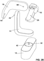
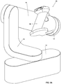
- Figure 1 shows a first controller 10 with three axes of movement in a first resting position, in an embodiment of the disclosed technology, and to Figures2A , 2B , and 2C , which show blown-apart versions of the controller of Figure 1 .
- a mounting base 12 is fixedly mounted, such as to an interior of a car, a table top, or the like. It can be mounted onto a console of a vehicle or fixed to a top surface either temporarily or permanently.
- the mounting base 12 when the controller is used for video games, one might clamp the mounting base 12 to a top of a table surface, whereas when used in an electric vehicle, it might be within a console and fixedly connected, such that it stays stationary with respect to a car chassis.
- the mounting base is described as being mounted to a top surface, the orientation of the mounting base may be adapted so that it may be mounted to a side surface, such as the surface of a door, or may include a dashboard mount.
- first linkage (not shown) a first flange 14 is rotatably connected to the mounting base 12.
- a second flange 16 is rotatably connected to the first flange 14 by way of a second linkage (not shown).
- first flange 14 In the neutral, or resting position, shown in Figure 1 , the first flange 14 is at a right angle relative to the mounting base 12, and the second flange 16 is at a right angle relative to the first flange 14.
- each of the first and second flanges 14 and 16 is generally L-shaped, and has a first end and a second end having a ninety degree turn therebetween.
- the first end 14a of first flange 14 has the first linkage passing therethrough, and the second end 14b of first flange 14 as well as the first end 16a of second flange 16 have the second linkage passing therethrough, as shown in Figure 1 .
- a joystick 26 extends between first and second ends 22 and 24, and is rotatable together with third flange 18 relative to second flange 16.
- the joystick can have a wider base 28 connected to second end 24 of the third flange 18 and a wider top region 30 connected to first end 22 of the third flange 18.
- the first and second ends 22 and 24 of third flange 18 are generally perpendicular to the mid-region 18, and to the second flange 16, in the illustrated resting position.
- An elongated length of the joystick 26 (the most elongated length or length desired to be perpendicular to a forearm of a person holding the joystick / passes through a clasped hand there-around) is angled between the first and second ends 22 and 24.
- the third flange 18 and/or the joystick 26 includes pushbuttons for secondary controls.
- joystick 26 includes, on top region 30 thereof, a plurality of pushbuttons 34, and the mid-region 20 of third flange 18 includes a pushbutton 36.
- the pushbuttons may control the horn, left and right turn signals, high beam headlights, and/or initiating and deactivating autopilot.
- secondary controls may be provided anywhere on controller 10, and using any suitable interface, and need not necessarily be pushbuttons or be on the third flange or joystick.
- the first, second, and third linkages rotatably connect two elements together such that many rotations back and forth can take place while the rotatable connection between the two elements linked, remain rotatably connected.
- the first and third linkages allow for 360 degrees of rotation around a single axis, whereas the maximum rotation of the second linkage (linkage of the P-link) may be less than 360 degrees, due to interference from the other links.
- the first, second, and third linkages can be any sort of elongated fastening mechanism such as a dowel, screw, or motor axle.
- first, second, and third linkages are, in at least one configuration, perpendicular to one another.
- the joystick 26 is above the mounting piece 12 when every flange is centered. As such, the joystick 26 is in a position to be moved around any of three axes, causing the corresponding flange to rotate with respect to the element to which it is rotatably connected. This will be shown/discussed with reference to Figures 3 - 9 below.
- the first flange 14 is also referred to herein as a "Y link", the second flange 16 as a “P link,” and the third flange 18 as an “R link.”
- Each link can rotate with respect to the link to which it is connected, or with respect to the mounting base 12. In embodiments, each link can only rotate with respect to a link to which it is connected.
- the Y link 14 can rotate with respect to the mounting base 12 in a manner which constitutes "yaw.”
- the P link 16 can rotate with respect to the Y link in a manner which constitutes "pitch”
- the R link 18 can rotate with respect to the P link in a manner which constitutes "roll”. Any combinations of changes of roll, pitch, and yaw are possible, though typically limited by the rotation of the forearm and/or wrist of the user of the controller.
- sensors for measuring the degree of rotation of flanges 14, 16, and 18 may be provided at the first, second, and third linkage points.
- the flanges 14, 16, and 18 may be hollow, at least in the region of the linkage points thereof.
- sensors, motors, and wiring thereof may be enclosed within the flanges, forming an exostructural arrangement.
- the motors may include any one or more of a direct drive motor, a pancake motor, and a limited angle torque motor.
- Figures 2B and 2C illustrate a specific embodiment in which each of mounting base 12 and flanges 14 and 18 includes a pancake motor 40 disposed within the flange adjacent to or surrounding the corresponding linkage.
- pancake motor relates to a motor having a printed armature with windings shaped as a disc.
- Each pancake motor 40 has extending therefrom an axle 42, adapted to fit into a corresponding bore 44 in a corresponding one of flanges 14 or 16, thereby to form the first, second, and third linkages.
- Figure 3 shows the controller 10 of Figure 1 with rotation around the yaw axis. This is accomplished by rotation of the first flange 14 relative to the mounting base 12, while the relationship between the first flange 14 and the second flange 16 remains unchanged.
- the Y link is pulled back, such that an acute angle, indicated by reference numeral 40 is defined between an edge of the mounting base 12 and the first end 14a of the Y link (first flange 14).
- the rotation of the Y-link with respect to mounting base 12 causes a change in yaw which can be recorded by a suitable sensor, for example measuring rotation at the first linkage point.
- Figure 4 shows the controller of Figure 1 with rotation around the pitch axis. This is accomplished by rotation of the second flange 16 relative to the first flange 14, while the relationship between the first flange 14 and the mounting base 12, and the relationship between the second flange 16 and the third flange 18, remain unchanged.
- the P link is rotated downward, such that a distance between the P link and the mounting base 12 is decreased relative to the resting position shown in Figure 1 .
- the rotation of the P-link with respect to first flange 14 causes a change in pitch which can be recorded by a suitable sensor, for example measuring rotation at the second linkage point.
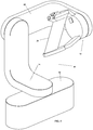
- Figure 5 shows the controller of Figure 1 with rotation around the roll axis. This is accomplished by rotation of the third flange 18 and the joystick 26 relative to the second flange 16, while the relationship between the first flange 14 and the mounting base 12, and the relationship between the first flange 14 and the second flange 16, remain unchanged.
- the R link is rotated counterclockwise. The rotation of the R-link with respect to second flange 16 causes a change in roll which can be recorded by a suitable sensor, for example measuring rotation at the third linkage point.
- Figure 6 shows the controller 10 of Figure 1 with rotations around the yaw and pitch axes.
- rotation of the second flange 16 (P-link) with respect to first flange 14 (Y-link) takes place around the second linkage, as described hereinabove with reference to Figure 4 .
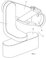
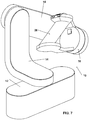
- Figure 7 shows the controller 10 of Figure 1 with rotations around the pitch and roll axes.
- the combination of rotating the third flange 18 and the joystick 26 with respect to the second flange 16, and rotating the second flange 16 with respect to the first flange 14 causes a change in roll and pitch simultaneously.
- Figures 8A and 8B show the controller of Figure 1 with rotations around the yaw, pitch, and roll axes.
- each element which can be rotated with respect to another, in an embodiment of the disclosed technology is so rotated.
- the Y-link (flange 14) is rotated back, similarly to the rotation shown in Figure 3
- the P-link (flange 16) is rotated downward, similarly to the rotation shown in Figure 4 .
- the R-link flange 18 and joystick 26
- Figure 8B the R-link is rotated clockwise, to a greater angular degree of rotation than that shown in Figure 8A .
- Rotation of the R link (flange 18 and joystick 26 with respect to the second flange 16) can be used to steer a vehicle left or right.
- Rotation of the P link (second flange 16 with respect to first flange 14) can be used for acceleration and deceleration of a vehicle.
- Rotation of the Y link (first flange 14 with respect to mounting base 12) can be used for fine control of steering, such that, per degree of rotation, steering has less magnitude for rotation of the Y link compared to rotation of the R link.
- the assignment of the Y-link and the R-link may be reversed, such that rotation of the Y-link is used to steer the vehicle left or right and rotation of the R-link is used for fine control of steering.
- Figure 9 shows the controller 10 of Figure 1 with rotations around the yaw and roll axes.
- the pitch remains constant, compared to Figure 1 (first flange 14 and second flange 16 remain at a 90 degree angle with respect to one another).
- the yaw is changed (the angle between the first flange 14 and the mounting base 12 is acute, and changes relative to the angle shown in Figure 1 ) as well as the roll (third flange 18 and joystick 26 are rotated counterclockwise with respect to the second flange 16).
- Controller 10 illustrated in Figures 1 to 9 is a controller suited for right handed use.
- An equivalent controller suited for left handed use would be a mirror image of the illustrated controller, and is considered within the scope of the present invention.
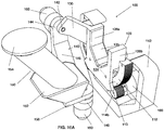
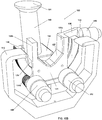
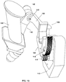
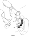
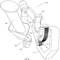
- Figures 10A and 10B show two perspective angles of a second controller 100 with three axes of movement in a first resting position, in an embodiment of the disclosed technology, and to Figure 11 , which shows a blown-apart version of the controller of Figures 10A and 10B .
- a generally U-shaped mounting base 112 is fixedly mounted, such as to an interior of a car, a table, or the like. It can be mounted onto a console of a vehicle or fixed to a top surface either temporarily or permanently. In examples not forming part of the claimed invention, when the controller is used for video games, one might clamp the mounting base 112 to a top surface of a table, whereas when used in an electric vehicle, it might be within a console and fixedly connected, such that it stays stationary with respect to a car chassis.
- the mounting base is described as being mounted to a top surface, the orientation of the mounting base may be adapted so that it may be mounted to a side surface, such as the surface of a door, or may include a dashboard mount.
- a pair of gears, or pinions, 114a and 114b are mounted to the motor axles 113, and can move relative to the curved rack 118.
- a generally U-shaped rack 118 is disposed above pinions 114a and 114b and in geared engagement therewith, such that rack 118 is fixed with respect to the mounting base 112, and pinions 114a and 114b are movable with respect to the rack 118 and to the mounting base 112.
- a first flange 120 is supported above rack 118, for example by a plurality of rollers 127, and is movable relative to the rack 118 and to the mounting base 112.
- Flange 120 includes a main body, also known as a wrist cradle, including front and back surfaces 124 connected by a generally U-shaped upper surface 125.
- the surfaces 124 and 125 together define a channel 126 having a generally U-shaped cross-section and accommodating rack 118, such that front and back surface 124 extend along sides of the rack 118, and are slidable relative thereto.
- a pair of side walls 128a and 128b extend upwards from upper surface 125 at opposing sides thereof. Extending from side wall 128a is a flange extension 130, which forms an obtuse angle with front surface 124 of the flange.
- the first flange 120 is rotatable, or movable, relative to the rack 118 and to the mounting base 112, by operation of the curved rack and pinion mechanism formed by pinions 114a and 114b and rack 118.
- a second flange 140 is rotatably connected to flange extension 130 of the first flange 120 by way of a second axle 142.
- flange 140 includes a first end portion 144 having a portal therethrough for axle 142, a mid-region 146 disposed at a 45 degree angle to the first end portion 144, and a second end portion 148 including a portal for an additional linkage.
- the second end portion 148 is disposed at a 45 degree angle to the mid-region 146 and at a 90 degree angle to the first end portion 144.
- an "end" of flange 140 is a portion which connects to another item and is defined by a furthest end of the flange until a bend in the flange, the bend occurring after a portal or a linkage passing there-through, such that the linkage is between the furthest end and bend.
- a joystick 150 is rotatably connected to second end 148 of the second flange 140 via an axle 151.
- the joystick can have a wider base 152, a wider top region 154, and a linking section 158.
- the linking section 158 has, in some embodiments, a portal through which axle 151 passes to connect the joystick 150 and base 152 to the second end 148 of the second flange 140.
- the joystick can rotate about the axle 151.
- the elongated length of the joystick 150 (the most elongated length or length desired to be perpendicular to a forearm of a person holding the joystick / passes through a clasped hand there-around) is angled at an acute angle, relative to base 152.
- the first flange 120 is centered with respect to rack 118, and rack 118 is centered between pinions 114a and 114b, such that a center point of the rack 118 is equidistant from each of the pinions.
- the first end 144 of the second flange 140 forms an acute angle with flange extension 130, such that a side wall of the second flange is generally parallel to front surface 124 of first flange 120.
- the linking section 158 of the joystick 150 and the second end 148 of second flange 140 form a right angle relative to one another.
- the axles 113, 142, and 151 rotatably connect two elements together such that many rotations back and forth can take place while the rotatable connection between the two elements linked, remain rotatably connected.
- the linkages can be any sort of elongated fastening mechanism such as a dowel, screw, or motor axle.
- axles 113, 142, and 151 are, in at least one configuration, perpendicular to one another.
- the joystick 150 In the resting position, the joystick 150 is in a position to be moved around any of three axes, causing the corresponding flange to rotate with respect to the element to which it is rotatably connected. This will be shown/discussed with reference to Figures 12 - 18 below.
- the first flange 120 is also referred to herein as a "R link”, the second flange 140 as a “P link,” and the linking section 158, as a "Y link.”
- Each link can rotate with respect to the link to which it is connected, or with respect to the mounting base 112. In embodiments, each link can only rotate with respect to a link to which it is connected.
- the R link 120 can rotate with respect to the mounting base 112 in a manner which constitutes "roll”.
- the P link 140 can rotate with respect to the R link in a manner which constitutes "pitch”
- the Y link 158 can rotate with respect to the P link in a manner which constitutes "yaw”. Any combinations of changes of roll, pitch, and yaw are possible, though typically limited by the rotation of the forearm and/or wrist of the user of the controller.
- motors 160 which introduce torque when the first axles 113, second axle 142, or third axle 151 are rotated with respect to another element.
- the greater the offset from the angle of the resting position the greater the torque. This prevents excess movement and can simulate torque one would feel when, for example, moving steering wheels left and right.
- the motors 160 connected to axles 113 generate force on the pinions 114 and rotate the first pinions 114 and first flange 120 relative to the rack 118 and mounting base 112.
- position encoders or other position measuring elements are disposed at linkages 113, 142, and/or 151, and may be used to measure turning angle of the elongated member associated therewith, and thus, the angle of turn of two elements with respect to one another.
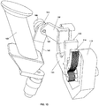
- Figure 12 shows the controller 100 of Figures 10A and 10B with rotation around the roll axis. This is accomplished by movement of first flange 120 relative to the mounting base 112 and rack 118 using the rack and pinion mechanism formed by rack 118 and pinions 114a and 114b. As seen in Figure 12 , first flange 120 and pinions 114 have rotated such that a center of rack 118 is disposed above pinion 114b, whereas the first flange 120 has moved along the rack 118 in the opposing direction, toward pinion 114a. At the same time, the relationship between the flange extension 130 of first flange 120 and the second flange 140 remains unchanged.
- the rotation of the R-link with respect to mounting base 112 causes a change in roll which can be recorded by a suitable sensor, such as elements 160 associated with linkages 113 and measuring rotation thereat.
- Figure 13 shows the controller 100 of Figures 10A and 10B with rotation around the pitch axis. This is accomplished by rotation of the second flange 140 relative to the first flange 120, while the relationship between the first flange 120 and the mounting base 112, and the relationship between the second flange 140 and the linking section 158 of joystick 150, remain unchanged.
- the P link is rotated outward, such that an angle between the first end 144 of the second flange 140 and the flange extension 130 increases relative to the resting position shown in Figure 10A , and such that a side surface of second flange 140 is no longer parallel with surface 124 of flange 120 but rather at an acute angle thereto.
- the rotation of the P-link with respect to first flange 120 causes a change in pitch which can be recorded by a suitable sensor, such as element 160 disposed adjacent to linkage 142 and measuring rotation thereat.
- Figure 14 shows the controller 100 of Figures 10A and 10B with rotation around the yaw axis. This is accomplished by rotating joystick 150 relative to the second flange 140, while the relationship between the first flange 120 and the mounting base 112, and the relationship between the first flange 120 and the second flange 140, remain unchanged.
- the Y link is rotated clockwise, when looking at the controller from above. Measurement of this angle of change (yaw) can be made within, or at, the linkage 151.
- Figure 15 shows the controller 100 of Figures 10A and 10B with rotations around the roll and pitch axes.
- rotation of the second flange 140 (P-link) with respect to first flange 120 (R-link) takes place around the second linkage 142, as described hereinabove with reference to Figure 13 .
- Figure 16 shows the controller 100 of Figures 10A and 10B with rotations around the pitch and yaw axes.
- the combination of rotating the joystick 150 with respect to the second flange 140, and rotating the second flange 140 with respect the first flange 120 causes a change in yaw and pitch simultaneously.
- Figures 17A , 17B , and 17C show the controller 100 of Figures 10A and 10B rotated around the yaw, pitch, and roll axes, in three different extent and direction combinations.
- each element which can be rotated with respect to another, in an embodiment of the disclosed technology, is so rotated.
- Rotation of the R link (flange 120 with respect to the mounting base 112) can be used to steer a vehicle left or right.
- Rotation of the P link (second flange 140 with respect to first flange 120) can be used for acceleration and deceleration of a vehicle.
- Rotation of the Y link (joystick 150 with respect to second flange 140) can be used for fine control of steering, such that, per degree of rotation, steering has less magnitude for rotation of the Y link compared to rotation of the R link.
- the assignment of the Y-link and the R-link may be reversed, such that rotation of the Y-link is used to steer the vehicle left or right and rotation of the R-link is used for fine control of steering.
- Figure 18 shows the controller 100 of Figures 10A and 10B with rotations around the yaw and roll axes.
- the pitch remains constant, compared to Figures 10A and 10B (a side surface of second flange 140 remains parallel to front surface 124 of first flange 120).
- the yaw is changed (the angle between linking portion 158 of joystick 150 and the second flange 140 is acute, and has changes relative to right angle shown in Figure 10A ) as well as the roll, which has changed similarly to the change shown in Figure 12 .
- the rotation of the R link is used at lower speeds for coarse steering maneuvers, such as turning and parking
- rotation of the Y link is used for fine steering adjustment for higher speed maneuvers, such as highway lane keeping or lane changes, or rotation of both may occur simultaneously.
- Controller 100 illustrated in Figures 10A to 18 is a controller suited for right handed use.
- An equivalent controller suited for left handed use would be a mirror image of the illustrated controller, and is considered within the scope of the present invention.
- any ordering of the links is considered to be within the scope of this application, provided that all three (R, P, and Y) are included.
- the present invention relates also to controllers in which the link order is RYP, PRY, PYR, and YRP.
Landscapes
- Engineering & Computer Science (AREA)
- Mechanical Engineering (AREA)
- Transportation (AREA)
- Automation & Control Theory (AREA)
- Chemical & Material Sciences (AREA)
- Combustion & Propulsion (AREA)
- Physics & Mathematics (AREA)
- General Physics & Mathematics (AREA)
- Robotics (AREA)
- Mechanical Control Devices (AREA)
- Switches With Compound Operations (AREA)
Claims (8)
- Dispositif de commande (10) comprenant :une base de montage à position fixe (12) ;une première bride (14) possédant une première extrémité (14a) et une seconde extrémité (14b) perpendiculaires l'une à l'autre, ladite première extrémité (14a) de ladite première bride (14) étant raccordée de manière rotative à ladite base de montage à position fixe (12) ;une deuxième bride (16) possédant une première extrémité (16a) et une seconde extrémité (16b) perpendiculaires l'une à l'autre, ladite première extrémité (16a) de ladite deuxième bride (16) étant raccordée de manière rotative à ladite seconde extrémité (14b) de ladite première bride (14) ; une troisième bride (18) généralement en forme de U possédant une zone médiane (20) et des première et seconde extrémités (22, 24), ladite zone médiane (20) étant raccordée de manière rotative à la seconde extrémité (16b) de ladite deuxième bride (16) et une manette formée entre lesdites première et seconde extrémités (22, 24) de ladite troisième bride (18), caractérisé en ce que le dispositif de commande (10) est conçu pour être utilisé pour commander un véhicule,- ladite rotation de ladite manette par rapport à ladite deuxième bride (16) étant conçue pour amener ledit véhicule à tourner à gauche ou à droite, et ladite rotation de ladite première bride (14) par rapport à ladite base de montage à position fixe (12) étant conçue pour amener ledit véhicule à tourner à gauche ou à droite à un degré moindre par degré de rotation que ladite rotation de ladite manette par rapport à ladite deuxième bride (16), ou- ladite rotation de ladite première bride (14) par rapport à ladite base de montage à position fixe (12) étant conçue pour amener ledit véhicule à tourner à gauche ou à droite, et ladite rotation de ladite manette de commande par rapport à ladite deuxième bride (16) étant conçue pour amener ledit véhicule à tourner à gauche ou à droite d'un degré moindre par degré de rotation que ladite rotation de ladite première bride (14) par rapport à ladite base de montage à position fixe (12).
- Dispositif de commande (10) selon la revendication 1, comprenant en outre un capteur de lacet conçu pour mesurer la rotation de ladite première bride (14) par rapport à ladite base de montage à position fixe (12).
- Dispositif de commande (10) selon la revendication 2, comprenant en outre un capteur de pas conçu pour mesurer la rotation de ladite deuxième bride (16) par rapport à ladite première bride (14).
- Dispositif de commande (10) selon la revendication 3, comprenant en outre un capteur de roulis conçu pour mesurer la rotation de ladite troisième bride (18) et de ladite manette par rapport à ladite deuxième bride (16).
- Dispositif de commande (10) selon la revendication 4, lesdites première et seconde extrémités (22, 24) de ladite troisième bride (18) étant sensiblement perpendiculaires à ladite seconde extrémité (14b) de ladite deuxième bride (16) et ladite seconde extrémité (14b) de ladite première bride (14) et ladite première extrémité (14a) de ladite deuxième bride (16) étant perpendiculaires l'une à l'autre.
- Dispositif de commande (10) selon la revendication 1,
la rotation de ladite deuxième bride (16) par rapport à ladite première bride (14) étant conçue pour amener ledit véhicule à accélérer ou à décélérer. - Dispositif de commande (10) selon la revendication 1,
au moins l'une de ladite première bride (14), de ladite deuxième bride (16), de ladite troisième bride (18) et de ladite base de montage (12) comprenant une cavité ; et
au moins une liaison reliant deux de ladite première bride (14), de ladite deuxième bride (16), de ladite troisième bride (18) et de ladite base de montage (12), ou au moins un moteur destiné à générer un couple et au moins un capteur destiné à mesurer le degré de rotation étant disposés dans ladite cavité. - Véhicule avec un dispositif de commande (10) selon l'une quelconque des revendications précédentes.
Priority Applications (1)
| Application Number | Priority Date | Filing Date | Title |
|---|---|---|---|
| HRP20191088TT HRP20191088T1 (hr) | 2016-08-15 | 2019-06-17 | Troosna igraća palica (joystick) |
Applications Claiming Priority (2)
| Application Number | Priority Date | Filing Date | Title |
|---|---|---|---|
| US15/236,708 US9823686B1 (en) | 2016-08-15 | 2016-08-15 | Three-axis motion joystick |
| US15/614,872 US9889874B1 (en) | 2016-08-15 | 2017-06-06 | Three-axis motion joystick |
Publications (3)
| Publication Number | Publication Date |
|---|---|
| EP3293600A2 EP3293600A2 (fr) | 2018-03-14 |
| EP3293600A3 EP3293600A3 (fr) | 2018-06-20 |
| EP3293600B1 true EP3293600B1 (fr) | 2019-06-05 |
Family
ID=59053987
Family Applications (1)
| Application Number | Title | Priority Date | Filing Date |
|---|---|---|---|
| EP17175248.8A Active EP3293600B1 (fr) | 2016-08-15 | 2017-06-09 | Manette à mouvement triaxial |
Country Status (4)
| Country | Link |
|---|---|
| US (1) | US9889874B1 (fr) |
| EP (1) | EP3293600B1 (fr) |
| HR (1) | HRP20191088T1 (fr) |
| WO (1) | WO2018034722A1 (fr) |
Families Citing this family (17)
| Publication number | Priority date | Publication date | Assignee | Title |
|---|---|---|---|---|
| US10118688B2 (en) * | 2015-08-18 | 2018-11-06 | Woodward, Inc. | Inherently balanced control stick |
| US12594069B2 (en) | 2015-10-02 | 2026-04-07 | Livsmed, Inc. | Handle assembly providing unlimited roll |
| US10959797B2 (en) | 2015-10-05 | 2021-03-30 | Flexdex, Inc. | Medical devices having smoothly articulating multi-cluster joints |
| US11896255B2 (en) | 2015-10-05 | 2024-02-13 | Flexdex, Inc. | End-effector jaw closure transmission systems for remote access tools |
| CN209548018U (zh) | 2016-02-25 | 2019-10-29 | 弗莱克斯德克斯公司 | 并联运动机构 |
| US11860662B2 (en) * | 2017-01-28 | 2024-01-02 | Excel Industries, Inc. | Control device |
| AT520763B1 (de) * | 2017-12-21 | 2022-09-15 | Hans Kuenz Gmbh | Kransteuerung |
| JP7180288B2 (ja) | 2018-11-01 | 2022-11-30 | スズキ株式会社 | 移動体 |
| JP2020169000A (ja) * | 2019-04-05 | 2020-10-15 | スズキ株式会社 | 電動車両の操作装置 |
| JP7300101B2 (ja) | 2019-05-08 | 2023-06-29 | スズキ株式会社 | 電動歩行補助車 |
| KR102829532B1 (ko) * | 2019-08-07 | 2025-07-07 | 현대자동차주식회사 | 자율주행차량의 거동 제어 장치 및 그 방법 |
| RU2720496C1 (ru) * | 2019-12-11 | 2020-04-30 | Адам Исаакович Львовский | Устройство контролируемого автопилота автомобиля |
| US11950966B2 (en) | 2020-06-02 | 2024-04-09 | Flexdex, Inc. | Surgical tool and assembly |
| EP4565150A4 (fr) | 2022-08-08 | 2025-12-10 | Crossfire Medical Inc | Ablation vasculaire segmentaire |
| WO2025199515A1 (fr) * | 2024-03-22 | 2025-09-25 | Vector Controls Inc. | Unités de commande et manettes de commande pour navire marin |
| WO2026082943A1 (fr) * | 2024-10-18 | 2026-04-23 | Deutsches Zentrum für Luft- und Raumfahrt e.V. | Dispositif de commande pour véhicule |
| US12546090B1 (en) * | 2025-05-14 | 2026-02-10 | Deere & Company | Reconfigurable steering device |
Family Cites Families (91)
| Publication number | Priority date | Publication date | Assignee | Title |
|---|---|---|---|---|
| US3011739A (en) * | 1960-04-06 | 1961-12-05 | Chance Vought Corp | Three axes side controller |
| US3028126A (en) * | 1960-05-10 | 1962-04-03 | Euclid C Holleman | Three axis controller |
| US3196709A (en) * | 1962-09-18 | 1965-07-27 | Richard A Bickford | Steering control with swivel handle |
| US3117649A (en) * | 1962-11-19 | 1964-01-14 | Clarence C Parton | Single handed triple control for automotive vehicles |
| US3299731A (en) * | 1964-04-07 | 1967-01-24 | Gen Precision Inc | Gimbal-type joystick |
| US3312123A (en) * | 1965-03-11 | 1967-04-04 | Ford Motor Co | Vehicle steering control |
| US3350956A (en) * | 1965-07-06 | 1967-11-07 | Gen Dynamics Corp | Six-degree of freedom integrated controller |
| US3388609A (en) * | 1967-03-22 | 1968-06-18 | Deere & Co | Single lever control mechanism |
| US3831633A (en) * | 1972-04-28 | 1974-08-27 | Caterpillar Tractor Co | Single lever control for actuating multiple control valves |
| US3897805A (en) * | 1972-06-23 | 1975-08-05 | Caterpillar Tractor Co | Three-way lever control for actuating a plurality of valves |
| US4027547A (en) * | 1975-12-17 | 1977-06-07 | Massey-Ferguson Inc. | Single lever control |
| US4069720A (en) * | 1976-11-05 | 1978-01-24 | Thor Wayne A | Two axis side controller for aircraft |
| US4427084A (en) * | 1981-02-10 | 1984-01-24 | Golf-Eze | Golf cart and similar vehicles |
| US4422345A (en) * | 1981-09-11 | 1983-12-27 | Deere & Company | Two-way control lever rotatable in cab wall for sound sealing |
| FR2565928B1 (fr) * | 1984-06-14 | 1989-12-29 | Elf France | Dispositif d'actionnement manuel en particulier pour une direction de motocycle |
| JPS61241077A (ja) * | 1985-04-17 | 1986-10-27 | 株式会社明電舎 | マスタ−マニプレ−タ |
| US4667909A (en) * | 1985-10-10 | 1987-05-26 | Alfred Curci | Single-stick control system for helicopters |
| US4920820A (en) * | 1985-10-15 | 1990-05-01 | Hyster Company | Vehicle steering control |
| CH672089A5 (fr) * | 1985-12-16 | 1989-10-31 | Sogeva Sa | |
| US5116180A (en) * | 1988-07-18 | 1992-05-26 | Spar Aerospace Limited | Human-in-the-loop machine control loop |
| US4895039A (en) * | 1988-07-20 | 1990-01-23 | Honeywell Inc. | Hand controller having pivot axis for minimizing forearm movement |
| US5019761A (en) * | 1989-02-21 | 1991-05-28 | Kraft Brett W | Force feedback control for backhoe |
| GB8904955D0 (en) * | 1989-03-03 | 1989-04-12 | Atomic Energy Authority Uk | Multi-axis hand controller |
| FR2644601B1 (fr) * | 1989-03-17 | 1992-01-24 | Eca | Dispositif d'actionnement en rotation d'un mecanisme et manche de commande incorporant un tel dispositif |
| US5107080A (en) * | 1989-12-01 | 1992-04-21 | Massachusetts Institute Of Technology | Multiple degree of freedom damped hand controls |
| US5182961A (en) * | 1991-07-30 | 1993-02-02 | Honeywell Inc. | Three degree of freedom translational axis hand controller mechanism |
| CA2062147C (fr) * | 1992-03-02 | 1995-07-25 | Kenji Hara | Dispositif de commande multi-axiale a manchet |
| US5477597A (en) * | 1993-04-14 | 1995-12-26 | Gemcor Engineering Corp. | Apparatus for positioning tooling |
| US5805140A (en) * | 1993-07-16 | 1998-09-08 | Immersion Corporation | High bandwidth force feedback interface using voice coils and flexures |
| US6437771B1 (en) * | 1995-01-18 | 2002-08-20 | Immersion Corporation | Force feedback device including flexure member between actuator and user object |
| US5456428A (en) * | 1993-07-21 | 1995-10-10 | Honeywell Inc. | Mechanically linked active sidesticks |
| US5625576A (en) * | 1993-10-01 | 1997-04-29 | Massachusetts Institute Of Technology | Force reflecting haptic interface |
| JP3212205B2 (ja) * | 1993-10-27 | 2001-09-25 | 株式会社小松製作所 | 装軌車両の操縦レバー装置 |
| US5503040A (en) * | 1993-11-12 | 1996-04-02 | Binagraphics, Inc. | Computer interface device |
| DE69517423D1 (de) * | 1994-04-11 | 2000-07-13 | Peter Neltoft | Gerät zur manuellen steuerung der bewegung eines realen oder imaginären objektes |
| US5724068A (en) * | 1995-09-07 | 1998-03-03 | Microsoft Corporation | Joystick with uniform center return force |
| US5655411A (en) * | 1995-10-23 | 1997-08-12 | Schaeff, Incorporation | Dual axis carriage assembly for a control handle |
| US5769363A (en) * | 1995-10-31 | 1998-06-23 | The Cessna Aircraft Company | Aircraft adjustable control stick |
| US6267673B1 (en) * | 1996-09-20 | 2001-07-31 | Nintendo Co., Ltd. | Video game system with state of next world dependent upon manner of entry from previous world via a portal |
| KR100240085B1 (ko) * | 1995-12-30 | 2000-01-15 | 토니헬 | 굴삭기의 조작장치 |
| US5755645A (en) * | 1997-01-09 | 1998-05-26 | Boston Biomotion, Inc. | Exercise apparatus |
| CA2278726C (fr) * | 1997-01-27 | 2004-08-31 | Immersion Corporation | Procede et appareil incluant un actionneur perfectionne procurant un retour d'effort bande large et realiste |
| JPH10214128A (ja) * | 1997-01-30 | 1998-08-11 | Yazaki Corp | ジョイスティック型多機能コントローラ |
| US5979264A (en) * | 1997-03-13 | 1999-11-09 | Ross-Hime Designs, Incorporated | Robotic manipulator |
| TW364092B (en) * | 1997-04-04 | 1999-07-11 | Matsushita Electric Industrial Co Ltd | A load sensor and a pointing equipment incorporating the same |
| US6573885B1 (en) * | 1999-03-22 | 2003-06-03 | Logitech Europe S.A. | Folded gear drive force feedback mechanism with direct drive sensors |
| US6222179B1 (en) * | 1999-06-10 | 2001-04-24 | Peter J. Mikan | Fiber optic control having joystick |
| US6425205B2 (en) * | 2000-03-29 | 2002-07-30 | Delphi Technologies, Inc. | Vehicle liftgate power operating system |
| FR2809048B1 (fr) * | 2000-05-18 | 2002-10-11 | Commissariat Energie Atomique | Bras de commande |
| DE50113363D1 (de) * | 2000-10-20 | 2008-01-24 | Deere & Co | Bedienungselement |
| US20020175467A1 (en) * | 2001-02-28 | 2002-11-28 | Dicus Jack T. | Joystick actuated vehicle suspension control system |
| US20020190948A1 (en) * | 2001-06-15 | 2002-12-19 | Coutant Alan R. | Arcuate track joystick assembly |
| JP3923774B2 (ja) * | 2001-10-16 | 2007-06-06 | アルプス電気株式会社 | 力覚付入力装置 |
| JP3852381B2 (ja) * | 2001-11-29 | 2006-11-29 | トヨタ自動車株式会社 | 車両操作装置 |
| US6722224B2 (en) * | 2002-01-07 | 2004-04-20 | Husco International, Inc. | Dual axis joystick for operating hydraulic valves |
| GB2385111B (en) * | 2002-02-08 | 2006-01-18 | Bamford Excavators Ltd | Control apparatus |
| JP4199951B2 (ja) * | 2002-03-06 | 2008-12-24 | アルプス電気株式会社 | バイワイヤ方式の車両用シフトレバー装置 |
| SE524018C2 (sv) * | 2002-10-03 | 2004-06-15 | Parker Hannifin Ab | Manöveranordning samt metod för manövrering av ett manöverobjekt |
| US6837124B2 (en) * | 2002-12-11 | 2005-01-04 | Tonic Fitness Technology, Inc. | Directly-driven power swing rod device without dead points |
| US6880855B2 (en) * | 2003-01-06 | 2005-04-19 | General Motors Corporation | Rotary driver control input device |
| FR2849937B1 (fr) * | 2003-01-13 | 2005-02-11 | Commissariat Energie Atomique | Interface de simulation manuelle |
| DE10305261A1 (de) * | 2003-02-07 | 2004-08-26 | Wittenstein Ag | Vorrichtung zum Steuern eines Fahrzeuges |
| EP1690774A4 (fr) * | 2003-12-01 | 2011-01-12 | Honda Motor Co Ltd | Poignee de direction et dispositif de direction |
| US7466303B2 (en) * | 2004-02-10 | 2008-12-16 | Sunnybrook Health Sciences Center | Device and process for manipulating real and virtual objects in three-dimensional space |
| US20060090588A1 (en) * | 2004-11-03 | 2006-05-04 | Eaton Corporation | Operator control device |
| WO2006066401A1 (fr) * | 2004-12-20 | 2006-06-29 | Simon Fraser University | Liaison spherique et commande à retour de force |
| JP2006334695A (ja) * | 2005-05-31 | 2006-12-14 | Kyoto Univ | 遠隔操縦装置 |
| US7783384B2 (en) * | 2006-05-31 | 2010-08-24 | Kraft Brett W | Ambidextrous robotic master controller |
| US7623945B2 (en) * | 2006-05-31 | 2009-11-24 | Kraft Telerobotics, Inc. | Robotic master controller |
| EP1876504B1 (fr) * | 2006-07-03 | 2011-09-21 | Force Dimension Technologies Sàrl | Préhenseur actif pour dispositifs haptiques |
| US7701161B2 (en) * | 2006-10-02 | 2010-04-20 | Honeywell International Inc. | Motor balanced active user interface assembly |
| US7843426B2 (en) * | 2006-11-15 | 2010-11-30 | Honeywell International Inc. | Active human-machine interface system including interposed sector gears |
| US8100029B2 (en) * | 2007-02-12 | 2012-01-24 | Mason Electric Co. | Control inceptor systems and associated methods |
| US7675258B2 (en) * | 2007-03-30 | 2010-03-09 | Caterpillar Inc. | Operator-control device for a machine |
| US8746103B2 (en) * | 2007-06-25 | 2014-06-10 | Quanser Consulting Inc. | Mechanical linkage |
| US8096206B2 (en) * | 2007-12-05 | 2012-01-17 | Liebherr-Aerospace Lindenberg Gmbh | Control device |
| US8235330B2 (en) * | 2008-03-12 | 2012-08-07 | Usercentrix, Llc | Rotational aircraft throttle interface |
| JP5155725B2 (ja) * | 2008-04-15 | 2013-03-06 | アルプス電気株式会社 | 多方向入力装置 |
| US20090266948A1 (en) * | 2008-04-29 | 2009-10-29 | Honeywell International Inc. | Human-machine interface two axis gimbal mechanism |
| US8087619B2 (en) * | 2008-07-30 | 2012-01-03 | Honeywell International, Inc. | Active control stick assembly including traction drive |
| US8881616B2 (en) * | 2010-03-11 | 2014-11-11 | Hdt Robotics, Inc. | High degree of freedom (DoF) controller |
| US9575504B2 (en) * | 2010-03-11 | 2017-02-21 | Hdt Expeditionary Systems, Inc. | High degree of freedom (DOF) controller |
| US8770055B2 (en) * | 2010-06-11 | 2014-07-08 | Mason Electric Company | Multi-axis pivot assembly for control sticks and associated systems and methods |
| US20120017714A1 (en) * | 2010-07-23 | 2012-01-26 | Walvoil Fluid Power Corp. | Grip control and grip control system for controlling machinery |
| CN103237633B (zh) * | 2010-11-30 | 2015-07-22 | 奥林巴斯株式会社 | 主操作输入装置以及主-从机械手 |
| JP5936914B2 (ja) * | 2011-08-04 | 2016-06-22 | オリンパス株式会社 | 操作入力装置およびこれを備えるマニピュレータシステム |
| US9051836B2 (en) * | 2012-02-10 | 2015-06-09 | Bell Helicopter Textron Inc. | Pilot control system with compact gimbal mechanism |
| JP2013255966A (ja) * | 2012-06-13 | 2013-12-26 | Olympus Corp | 自重補償付き直動機構、操作入力装置、及び手術支援システム |
| BR102013021915A2 (pt) * | 2013-08-28 | 2015-08-04 | Chafic Samir Feguri | Sistema de direção aplicado em veículos automotores |
| US9134187B1 (en) * | 2013-10-21 | 2015-09-15 | Advanced Input Devices, Inc. | Force sensing multi-axis gimbaled device |
| US10118688B2 (en) * | 2015-08-18 | 2018-11-06 | Woodward, Inc. | Inherently balanced control stick |
-
2017
- 2017-06-06 US US15/614,872 patent/US9889874B1/en active Active
- 2017-06-08 WO PCT/US2017/036533 patent/WO2018034722A1/fr not_active Ceased
- 2017-06-09 EP EP17175248.8A patent/EP3293600B1/fr active Active
-
2019
- 2019-06-17 HR HRP20191088TT patent/HRP20191088T1/hr unknown
Non-Patent Citations (1)
| Title |
|---|
| None * |
Also Published As
| Publication number | Publication date |
|---|---|
| EP3293600A3 (fr) | 2018-06-20 |
| US9889874B1 (en) | 2018-02-13 |
| HRP20191088T1 (hr) | 2019-09-20 |
| US20180043921A1 (en) | 2018-02-15 |
| WO2018034722A1 (fr) | 2018-02-22 |
| EP3293600A2 (fr) | 2018-03-14 |
Similar Documents
| Publication | Publication Date | Title |
|---|---|---|
| EP3293600B1 (fr) | Manette à mouvement triaxial | |
| CA2165030C (fr) | Vehicule omnidirectionnel; les commandes correspondantes | |
| JP5131523B2 (ja) | 車両用操舵装置 | |
| KR100303588B1 (ko) | 동력식조향시스템 | |
| JP3627120B2 (ja) | 車両用操舵装置 | |
| JP5131522B2 (ja) | 車両用操舵装置 | |
| JP4387935B2 (ja) | 車両用操作装置 | |
| JP4026131B2 (ja) | 車両用電動ステアリング | |
| JP6837910B2 (ja) | 全方向移動車両 | |
| EP1342643B1 (fr) | Actionneurs de direction | |
| JP3560403B2 (ja) | 全方向移動車両およびその制御方法 | |
| ITRM970347A1 (it) | Complesso di elementi di comando per il controllo del movimento longitudinale e trasversale di autoveicoli | |
| US9823686B1 (en) | Three-axis motion joystick | |
| US20170274921A1 (en) | Three-Axis Motion Joystick | |
| ITRM970356A1 (it) | Complesso di elementi di comando per il controllo del movimento longitudinale e trasversale di un autoveicolo | |
| JP4193664B2 (ja) | 操舵入力装置 | |
| WO2015132911A1 (fr) | Dispositif de chariot | |
| KR20210081858A (ko) | 차량의 핸들 조절 장치 | |
| JPH11314571A (ja) | 車両横運動制御用操作素子装置 | |
| JP2007038059A (ja) | 作業補助装置 | |
| JP2007245263A (ja) | 無慣性タイプの荷重取扱装置 | |
| JP4300636B2 (ja) | 無軌道搬送車 | |
| JP4539951B2 (ja) | 入力操作装置 | |
| JP4609615B2 (ja) | 車両の操舵装置 | |
| KR101755885B1 (ko) | Atv 제어기구장치 |
Legal Events
| Date | Code | Title | Description |
|---|---|---|---|
| PUAI | Public reference made under article 153(3) epc to a published international application that has entered the european phase |
Free format text: ORIGINAL CODE: 0009012 |
|
| STAA | Information on the status of an ep patent application or granted ep patent |
Free format text: STATUS: THE APPLICATION HAS BEEN PUBLISHED |
|
| AK | Designated contracting states |
Kind code of ref document: A2 Designated state(s): AL AT BE BG CH CY CZ DE DK EE ES FI FR GB GR HR HU IE IS IT LI LT LU LV MC MK MT NL NO PL PT RO RS SE SI SK SM TR |
|
| AX | Request for extension of the european patent |
Extension state: BA ME |
|
| PUAL | Search report despatched |
Free format text: ORIGINAL CODE: 0009013 |
|
| AK | Designated contracting states |
Kind code of ref document: A3 Designated state(s): AL AT BE BG CH CY CZ DE DK EE ES FI FR GB GR HR HU IE IS IT LI LT LU LV MC MK MT NL NO PL PT RO RS SE SI SK SM TR |
|
| AX | Request for extension of the european patent |
Extension state: BA ME |
|
| RIC1 | Information provided on ipc code assigned before grant |
Ipc: G05G 9/047 20060101AFI20180514BHEP Ipc: G05G 9/04 20060101ALI20180514BHEP Ipc: B62D 1/12 20060101ALI20180514BHEP Ipc: B60K 26/02 20060101ALI20180514BHEP |
|
| STAA | Information on the status of an ep patent application or granted ep patent |
Free format text: STATUS: REQUEST FOR EXAMINATION WAS MADE |
|
| 17P | Request for examination filed |
Effective date: 20181001 |
|
| RBV | Designated contracting states (corrected) |
Designated state(s): AL AT BE BG CH CY CZ DE DK EE ES FI FR GB GR HR HU IE IS IT LI LT LU LV MC MK MT NL NO PL PT RO RS SE SI SK SM TR |
|
| GRAP | Despatch of communication of intention to grant a patent |
Free format text: ORIGINAL CODE: EPIDOSNIGR1 |
|
| STAA | Information on the status of an ep patent application or granted ep patent |
Free format text: STATUS: GRANT OF PATENT IS INTENDED |
|
| GRAS | Grant fee paid |
Free format text: ORIGINAL CODE: EPIDOSNIGR3 |
|
| INTG | Intention to grant announced |
Effective date: 20190318 |
|
| GRAA | (expected) grant |
Free format text: ORIGINAL CODE: 0009210 |
|
| STAA | Information on the status of an ep patent application or granted ep patent |
Free format text: STATUS: THE PATENT HAS BEEN GRANTED |
|
| AK | Designated contracting states |
Kind code of ref document: B1 Designated state(s): AL AT BE BG CH CY CZ DE DK EE ES FI FR GB GR HR HU IE IS IT LI LT LU LV MC MK MT NL NO PL PT RO RS SE SI SK SM TR |
|
| REG | Reference to a national code |
Ref country code: GB Ref legal event code: FG4D |
|
| REG | Reference to a national code |
Ref country code: CH Ref legal event code: EP |
|
| REG | Reference to a national code |
Ref country code: AT Ref legal event code: REF Ref document number: 1140630 Country of ref document: AT Kind code of ref document: T Effective date: 20190615 |
|
| REG | Reference to a national code |
Ref country code: HR Ref legal event code: TUEP Ref document number: P20191088 Country of ref document: HR |
|
| REG | Reference to a national code |
Ref country code: DE Ref legal event code: R096 Ref document number: 602017004284 Country of ref document: DE |
|
| REG | Reference to a national code |
Ref country code: IE Ref legal event code: FG4D |
|
| REG | Reference to a national code |
Ref country code: SE Ref legal event code: TRGR |
|
| REG | Reference to a national code |
Ref country code: HR Ref legal event code: ODRP Ref document number: P20191088 Country of ref document: HR Payment date: 20190619 Year of fee payment: 3 |
|
| REG | Reference to a national code |
Ref country code: HR Ref legal event code: T1PR Ref document number: P20191088 Country of ref document: HR |
|
| REG | Reference to a national code |
Ref country code: NL Ref legal event code: MP Effective date: 20190605 |
|
| REG | Reference to a national code |
Ref country code: LT Ref legal event code: MG4D |
|
| PG25 | Lapsed in a contracting state [announced via postgrant information from national office to epo] |
Ref country code: NO Free format text: LAPSE BECAUSE OF FAILURE TO SUBMIT A TRANSLATION OF THE DESCRIPTION OR TO PAY THE FEE WITHIN THE PRESCRIBED TIME-LIMIT Effective date: 20190905 Ref country code: ES Free format text: LAPSE BECAUSE OF FAILURE TO SUBMIT A TRANSLATION OF THE DESCRIPTION OR TO PAY THE FEE WITHIN THE PRESCRIBED TIME-LIMIT Effective date: 20190605 Ref country code: LT Free format text: LAPSE BECAUSE OF FAILURE TO SUBMIT A TRANSLATION OF THE DESCRIPTION OR TO PAY THE FEE WITHIN THE PRESCRIBED TIME-LIMIT Effective date: 20190605 Ref country code: AL Free format text: LAPSE BECAUSE OF FAILURE TO SUBMIT A TRANSLATION OF THE DESCRIPTION OR TO PAY THE FEE WITHIN THE PRESCRIBED TIME-LIMIT Effective date: 20190605 Ref country code: FI Free format text: LAPSE BECAUSE OF FAILURE TO SUBMIT A TRANSLATION OF THE DESCRIPTION OR TO PAY THE FEE WITHIN THE PRESCRIBED TIME-LIMIT Effective date: 20190605 |
|
| PG25 | Lapsed in a contracting state [announced via postgrant information from national office to epo] |
Ref country code: BG Free format text: LAPSE BECAUSE OF FAILURE TO SUBMIT A TRANSLATION OF THE DESCRIPTION OR TO PAY THE FEE WITHIN THE PRESCRIBED TIME-LIMIT Effective date: 20190905 Ref country code: GR Free format text: LAPSE BECAUSE OF FAILURE TO SUBMIT A TRANSLATION OF THE DESCRIPTION OR TO PAY THE FEE WITHIN THE PRESCRIBED TIME-LIMIT Effective date: 20190906 Ref country code: LV Free format text: LAPSE BECAUSE OF FAILURE TO SUBMIT A TRANSLATION OF THE DESCRIPTION OR TO PAY THE FEE WITHIN THE PRESCRIBED TIME-LIMIT Effective date: 20190605 Ref country code: RS Free format text: LAPSE BECAUSE OF FAILURE TO SUBMIT A TRANSLATION OF THE DESCRIPTION OR TO PAY THE FEE WITHIN THE PRESCRIBED TIME-LIMIT Effective date: 20190605 |
|
| PG25 | Lapsed in a contracting state [announced via postgrant information from national office to epo] |
Ref country code: SK Free format text: LAPSE BECAUSE OF FAILURE TO SUBMIT A TRANSLATION OF THE DESCRIPTION OR TO PAY THE FEE WITHIN THE PRESCRIBED TIME-LIMIT Effective date: 20190605 Ref country code: RO Free format text: LAPSE BECAUSE OF FAILURE TO SUBMIT A TRANSLATION OF THE DESCRIPTION OR TO PAY THE FEE WITHIN THE PRESCRIBED TIME-LIMIT Effective date: 20190605 Ref country code: CZ Free format text: LAPSE BECAUSE OF FAILURE TO SUBMIT A TRANSLATION OF THE DESCRIPTION OR TO PAY THE FEE WITHIN THE PRESCRIBED TIME-LIMIT Effective date: 20190605 Ref country code: PT Free format text: LAPSE BECAUSE OF FAILURE TO SUBMIT A TRANSLATION OF THE DESCRIPTION OR TO PAY THE FEE WITHIN THE PRESCRIBED TIME-LIMIT Effective date: 20191007 Ref country code: NL Free format text: LAPSE BECAUSE OF FAILURE TO SUBMIT A TRANSLATION OF THE DESCRIPTION OR TO PAY THE FEE WITHIN THE PRESCRIBED TIME-LIMIT Effective date: 20190605 Ref country code: EE Free format text: LAPSE BECAUSE OF FAILURE TO SUBMIT A TRANSLATION OF THE DESCRIPTION OR TO PAY THE FEE WITHIN THE PRESCRIBED TIME-LIMIT Effective date: 20190605 |
|
| PG25 | Lapsed in a contracting state [announced via postgrant information from national office to epo] |
Ref country code: SM Free format text: LAPSE BECAUSE OF FAILURE TO SUBMIT A TRANSLATION OF THE DESCRIPTION OR TO PAY THE FEE WITHIN THE PRESCRIBED TIME-LIMIT Effective date: 20190605 Ref country code: IS Free format text: LAPSE BECAUSE OF FAILURE TO SUBMIT A TRANSLATION OF THE DESCRIPTION OR TO PAY THE FEE WITHIN THE PRESCRIBED TIME-LIMIT Effective date: 20191005 |
|
| REG | Reference to a national code |
Ref country code: DE Ref legal event code: R097 Ref document number: 602017004284 Country of ref document: DE |
|
| REG | Reference to a national code |
Ref country code: BE Ref legal event code: MM Effective date: 20190630 |
|
| PG25 | Lapsed in a contracting state [announced via postgrant information from national office to epo] |
Ref country code: MC Free format text: LAPSE BECAUSE OF FAILURE TO SUBMIT A TRANSLATION OF THE DESCRIPTION OR TO PAY THE FEE WITHIN THE PRESCRIBED TIME-LIMIT Effective date: 20190605 Ref country code: TR Free format text: LAPSE BECAUSE OF FAILURE TO SUBMIT A TRANSLATION OF THE DESCRIPTION OR TO PAY THE FEE WITHIN THE PRESCRIBED TIME-LIMIT Effective date: 20190605 |
|
| PLBE | No opposition filed within time limit |
Free format text: ORIGINAL CODE: 0009261 |
|
| STAA | Information on the status of an ep patent application or granted ep patent |
Free format text: STATUS: NO OPPOSITION FILED WITHIN TIME LIMIT |
|
| PG25 | Lapsed in a contracting state [announced via postgrant information from national office to epo] |
Ref country code: IE Free format text: LAPSE BECAUSE OF NON-PAYMENT OF DUE FEES Effective date: 20190609 Ref country code: DK Free format text: LAPSE BECAUSE OF FAILURE TO SUBMIT A TRANSLATION OF THE DESCRIPTION OR TO PAY THE FEE WITHIN THE PRESCRIBED TIME-LIMIT Effective date: 20190605 Ref country code: PL Free format text: LAPSE BECAUSE OF FAILURE TO SUBMIT A TRANSLATION OF THE DESCRIPTION OR TO PAY THE FEE WITHIN THE PRESCRIBED TIME-LIMIT Effective date: 20190605 |
|
| 26N | No opposition filed |
Effective date: 20200306 |
|
| PG25 | Lapsed in a contracting state [announced via postgrant information from national office to epo] |
Ref country code: BE Free format text: LAPSE BECAUSE OF NON-PAYMENT OF DUE FEES Effective date: 20190630 Ref country code: LU Free format text: LAPSE BECAUSE OF NON-PAYMENT OF DUE FEES Effective date: 20190609 Ref country code: SI Free format text: LAPSE BECAUSE OF FAILURE TO SUBMIT A TRANSLATION OF THE DESCRIPTION OR TO PAY THE FEE WITHIN THE PRESCRIBED TIME-LIMIT Effective date: 20190605 |
|
| REG | Reference to a national code |
Ref country code: HR Ref legal event code: ODRP Ref document number: P20191088 Country of ref document: HR Payment date: 20200422 Year of fee payment: 4 |
|
| REG | Reference to a national code |
Ref country code: CH Ref legal event code: PL |
|
| PG25 | Lapsed in a contracting state [announced via postgrant information from national office to epo] |
Ref country code: CH Free format text: LAPSE BECAUSE OF NON-PAYMENT OF DUE FEES Effective date: 20200630 Ref country code: LI Free format text: LAPSE BECAUSE OF NON-PAYMENT OF DUE FEES Effective date: 20200630 |
|
| PG25 | Lapsed in a contracting state [announced via postgrant information from national office to epo] |
Ref country code: CY Free format text: LAPSE BECAUSE OF FAILURE TO SUBMIT A TRANSLATION OF THE DESCRIPTION OR TO PAY THE FEE WITHIN THE PRESCRIBED TIME-LIMIT Effective date: 20190605 |
|
| REG | Reference to a national code |
Ref country code: HR Ref legal event code: ODRP Ref document number: P20191088 Country of ref document: HR Payment date: 20210602 Year of fee payment: 5 |
|
| PG25 | Lapsed in a contracting state [announced via postgrant information from national office to epo] |
Ref country code: HU Free format text: LAPSE BECAUSE OF FAILURE TO SUBMIT A TRANSLATION OF THE DESCRIPTION OR TO PAY THE FEE WITHIN THE PRESCRIBED TIME-LIMIT; INVALID AB INITIO Effective date: 20170609 Ref country code: MT Free format text: LAPSE BECAUSE OF FAILURE TO SUBMIT A TRANSLATION OF THE DESCRIPTION OR TO PAY THE FEE WITHIN THE PRESCRIBED TIME-LIMIT Effective date: 20190605 |
|
| REG | Reference to a national code |
Ref country code: AT Ref legal event code: UEP Ref document number: 1140630 Country of ref document: AT Kind code of ref document: T Effective date: 20190605 |
|
| REG | Reference to a national code |
Ref country code: HR Ref legal event code: ODRP Ref document number: P20191088 Country of ref document: HR Payment date: 20220404 Year of fee payment: 6 |
|
| PG25 | Lapsed in a contracting state [announced via postgrant information from national office to epo] |
Ref country code: MK Free format text: LAPSE BECAUSE OF FAILURE TO SUBMIT A TRANSLATION OF THE DESCRIPTION OR TO PAY THE FEE WITHIN THE PRESCRIBED TIME-LIMIT Effective date: 20190605 |
|
| REG | Reference to a national code |
Ref country code: HR Ref legal event code: ODRP Ref document number: P20191088 Country of ref document: HR Payment date: 20230406 Year of fee payment: 7 |
|
| REG | Reference to a national code |
Ref country code: HR Ref legal event code: ODRP Ref document number: P20191088 Country of ref document: HR Payment date: 20240412 Year of fee payment: 8 |
|
| REG | Reference to a national code |
Ref country code: HR Ref legal event code: ODRP Ref document number: P20191088 Country of ref document: HR Payment date: 20250422 Year of fee payment: 9 |
|
| PGFP | Annual fee paid to national office [announced via postgrant information from national office to epo] |
Ref country code: DE Payment date: 20250423 Year of fee payment: 9 |
|
| PGFP | Annual fee paid to national office [announced via postgrant information from national office to epo] |
Ref country code: GB Payment date: 20250425 Year of fee payment: 9 |
|
| PGFP | Annual fee paid to national office [announced via postgrant information from national office to epo] |
Ref country code: IT Payment date: 20250422 Year of fee payment: 9 |
|
| PGFP | Annual fee paid to national office [announced via postgrant information from national office to epo] |
Ref country code: HR Payment date: 20250422 Year of fee payment: 9 |
|
| PGFP | Annual fee paid to national office [announced via postgrant information from national office to epo] |
Ref country code: FR Payment date: 20250422 Year of fee payment: 9 |
|
| PGFP | Annual fee paid to national office [announced via postgrant information from national office to epo] |
Ref country code: AT Payment date: 20250424 Year of fee payment: 9 |
|
| PGFP | Annual fee paid to national office [announced via postgrant information from national office to epo] |
Ref country code: SE Payment date: 20250425 Year of fee payment: 9 |