EP3293603A1 - Terminal mobile et son procédé de commande - Google Patents
Terminal mobile et son procédé de commande Download PDFInfo
- Publication number
- EP3293603A1 EP3293603A1 EP17182277.8A EP17182277A EP3293603A1 EP 3293603 A1 EP3293603 A1 EP 3293603A1 EP 17182277 A EP17182277 A EP 17182277A EP 3293603 A1 EP3293603 A1 EP 3293603A1
- Authority
- EP
- European Patent Office
- Prior art keywords
- fob
- mobile terminal
- display
- connector
- main body
- Prior art date
- Legal status (The legal status is an assumption and is not a legal conclusion. Google has not performed a legal analysis and makes no representation as to the accuracy of the status listed.)
- Granted
Links
Images


Classifications
-
- H—ELECTRICITY
- H04—ELECTRIC COMMUNICATION TECHNIQUE
- H04M—TELEPHONIC COMMUNICATION
- H04M1/00—Substation equipment, e.g. for use by subscribers
- H04M1/02—Constructional features of telephone sets
- H04M1/0202—Portable telephone sets, e.g. cordless phones, mobile phones or bar type handsets
- H04M1/0254—Portable telephone sets, e.g. cordless phones, mobile phones or bar type handsets comprising one or a plurality of mechanically detachable modules
- H04M1/0256—Portable telephone sets, e.g. cordless phones, mobile phones or bar type handsets comprising one or a plurality of mechanically detachable modules wherein the modules are operable in the detached state, e.g. one module for the user interface and one module for the transceiver
-
- A—HUMAN NECESSITIES
- A61—MEDICAL OR VETERINARY SCIENCE; HYGIENE
- A61B—DIAGNOSIS; SURGERY; IDENTIFICATION
- A61B5/00—Measuring for diagnostic purposes; Identification of persons
- A61B5/0002—Remote monitoring of patients using telemetry, e.g. transmission of vital signals via a communication network
- A61B5/0015—Remote monitoring of patients using telemetry, e.g. transmission of vital signals via a communication network characterised by features of the telemetry system
- A61B5/0022—Monitoring a patient using a global network, e.g. telephone networks, internet
-
- B—PERFORMING OPERATIONS; TRANSPORTING
- B60—VEHICLES IN GENERAL
- B60R—VEHICLES, VEHICLE FITTINGS, OR VEHICLE PARTS, NOT OTHERWISE PROVIDED FOR
- B60R25/00—Fittings or systems for preventing or indicating unauthorised use or theft of vehicles
- B60R25/20—Means to switch the anti-theft system on or off
- B60R25/24—Means to switch the anti-theft system on or off using electronic identifiers containing a code not memorised by the user
-
- H—ELECTRICITY
- H04—ELECTRIC COMMUNICATION TECHNIQUE
- H04M—TELEPHONIC COMMUNICATION
- H04M1/00—Substation equipment, e.g. for use by subscribers
- H04M1/72—Mobile telephones; Cordless telephones, i.e. devices for establishing wireless links to base stations without route selection
- H04M1/724—User interfaces specially adapted for cordless or mobile telephones
- H04M1/72403—User interfaces specially adapted for cordless or mobile telephones with means for local support of applications that increase the functionality
- H04M1/72409—User interfaces specially adapted for cordless or mobile telephones with means for local support of applications that increase the functionality by interfacing with external accessories
- H04M1/72415—User interfaces specially adapted for cordless or mobile telephones with means for local support of applications that increase the functionality by interfacing with external accessories for remote control of appliances
-
- A—HUMAN NECESSITIES
- A61—MEDICAL OR VETERINARY SCIENCE; HYGIENE
- A61B—DIAGNOSIS; SURGERY; IDENTIFICATION
- A61B5/00—Measuring for diagnostic purposes; Identification of persons
- A61B5/02—Detecting, measuring or recording for evaluating the cardiovascular system, e.g. pulse, heart rate, blood pressure or blood flow
- A61B5/024—Measuring pulse rate or heart rate
- A61B5/02416—Measuring pulse rate or heart rate using photoplethysmograph signals, e.g. generated by infrared radiation
-
- A—HUMAN NECESSITIES
- A61—MEDICAL OR VETERINARY SCIENCE; HYGIENE
- A61B—DIAGNOSIS; SURGERY; IDENTIFICATION
- A61B5/00—Measuring for diagnostic purposes; Identification of persons
- A61B5/103—Measuring devices for testing the shape, pattern, colour, size or movement of the body or parts thereof, for diagnostic purposes
- A61B5/11—Measuring movement of the entire body or parts thereof, e.g. head or hand tremor or mobility of a limb
- A61B5/1118—Determining activity level
-
- A—HUMAN NECESSITIES
- A61—MEDICAL OR VETERINARY SCIENCE; HYGIENE
- A61B—DIAGNOSIS; SURGERY; IDENTIFICATION
- A61B5/00—Measuring for diagnostic purposes; Identification of persons
- A61B5/68—Arrangements of detecting, measuring or recording means, e.g. sensors, in relation to patient
- A61B5/6801—Arrangements of detecting, measuring or recording means, e.g. sensors, in relation to patient specially adapted to be attached to or worn on the body surface
- A61B5/6802—Sensor mounted on worn items
- A61B5/681—Wristwatch-type devices
-
- A—HUMAN NECESSITIES
- A61—MEDICAL OR VETERINARY SCIENCE; HYGIENE
- A61B—DIAGNOSIS; SURGERY; IDENTIFICATION
- A61B5/00—Measuring for diagnostic purposes; Identification of persons
- A61B5/68—Arrangements of detecting, measuring or recording means, e.g. sensors, in relation to patient
- A61B5/6801—Arrangements of detecting, measuring or recording means, e.g. sensors, in relation to patient specially adapted to be attached to or worn on the body surface
- A61B5/6813—Specially adapted to be attached to a specific body part
- A61B5/6824—Arm or wrist
-
- A—HUMAN NECESSITIES
- A61—MEDICAL OR VETERINARY SCIENCE; HYGIENE
- A61B—DIAGNOSIS; SURGERY; IDENTIFICATION
- A61B5/00—Measuring for diagnostic purposes; Identification of persons
- A61B5/68—Arrangements of detecting, measuring or recording means, e.g. sensors, in relation to patient
- A61B5/6801—Arrangements of detecting, measuring or recording means, e.g. sensors, in relation to patient specially adapted to be attached to or worn on the body surface
- A61B5/683—Means for maintaining contact with the body
- A61B5/6831—Straps, bands or harnesses
-
- G—PHYSICS
- G06—COMPUTING OR CALCULATING; COUNTING
- G06F—ELECTRIC DIGITAL DATA PROCESSING
- G06F1/00—Details not covered by groups G06F3/00 - G06F13/00 and G06F21/00
- G06F1/16—Constructional details or arrangements
- G06F1/1613—Constructional details or arrangements for portable computers
- G06F1/163—Wearable computers, e.g. on a belt
-
- G—PHYSICS
- G06—COMPUTING OR CALCULATING; COUNTING
- G06F—ELECTRIC DIGITAL DATA PROCESSING
- G06F1/00—Details not covered by groups G06F3/00 - G06F13/00 and G06F21/00
- G06F1/16—Constructional details or arrangements
- G06F1/1613—Constructional details or arrangements for portable computers
- G06F1/1633—Constructional details or arrangements of portable computers not specific to the type of enclosures covered by groups G06F1/1615 - G06F1/1626
- G06F1/1637—Details related to the display arrangement, including those related to the mounting of the display in the housing
- G06F1/1643—Details related to the display arrangement, including those related to the mounting of the display in the housing the display being associated to a digitizer, e.g. laptops that can be used as penpads
-
- G—PHYSICS
- G06—COMPUTING OR CALCULATING; COUNTING
- G06F—ELECTRIC DIGITAL DATA PROCESSING
- G06F1/00—Details not covered by groups G06F3/00 - G06F13/00 and G06F21/00
- G06F1/16—Constructional details or arrangements
- G06F1/1613—Constructional details or arrangements for portable computers
- G06F1/1633—Constructional details or arrangements of portable computers not specific to the type of enclosures covered by groups G06F1/1615 - G06F1/1626
- G06F1/1637—Details related to the display arrangement, including those related to the mounting of the display in the housing
- G06F1/1654—Details related to the display arrangement, including those related to the mounting of the display in the housing the display being detachable, e.g. for remote use
-
- G—PHYSICS
- G07—CHECKING-DEVICES
- G07C—TIME OR ATTENDANCE REGISTERS; REGISTERING OR INDICATING THE WORKING OF MACHINES; GENERATING RANDOM NUMBERS; VOTING OR LOTTERY APPARATUS; ARRANGEMENTS, SYSTEMS OR APPARATUS FOR CHECKING NOT PROVIDED FOR ELSEWHERE
- G07C9/00—Individual registration on entry or exit
- G07C9/00174—Electronically operated locks; Circuits therefor; Nonmechanical keys therefor, e.g. passive or active electrical keys or other data carriers without mechanical keys
- G07C9/00309—Electronically operated locks; Circuits therefor; Nonmechanical keys therefor, e.g. passive or active electrical keys or other data carriers without mechanical keys operated with bidirectional data transmission between data carrier and locks
-
- G—PHYSICS
- G08—SIGNALLING
- G08C—TRANSMISSION SYSTEMS FOR MEASURED VALUES, CONTROL OR SIMILAR SIGNALS
- G08C17/00—Arrangements for transmitting signals characterised by the use of a wireless electrical link
- G08C17/02—Arrangements for transmitting signals characterised by the use of a wireless electrical link using a radio link
-
- G—PHYSICS
- G16—INFORMATION AND COMMUNICATION TECHNOLOGY [ICT] SPECIALLY ADAPTED FOR SPECIFIC APPLICATION FIELDS
- G16H—HEALTHCARE INFORMATICS, i.e. INFORMATION AND COMMUNICATION TECHNOLOGY [ICT] SPECIALLY ADAPTED FOR THE HANDLING OR PROCESSING OF MEDICAL OR HEALTHCARE DATA
- G16H40/00—ICT specially adapted for the management or administration of healthcare resources or facilities; ICT specially adapted for the management or operation of medical equipment or devices
- G16H40/60—ICT specially adapted for the management or administration of healthcare resources or facilities; ICT specially adapted for the management or operation of medical equipment or devices for the operation of medical equipment or devices
- G16H40/67—ICT specially adapted for the management or administration of healthcare resources or facilities; ICT specially adapted for the management or operation of medical equipment or devices for the operation of medical equipment or devices for remote operation
-
- G—PHYSICS
- G16—INFORMATION AND COMMUNICATION TECHNOLOGY [ICT] SPECIALLY ADAPTED FOR SPECIFIC APPLICATION FIELDS
- G16Z—INFORMATION AND COMMUNICATION TECHNOLOGY [ICT] SPECIALLY ADAPTED FOR SPECIFIC APPLICATION FIELDS, NOT OTHERWISE PROVIDED FOR
- G16Z99/00—Subject matter not provided for in other main groups of this subclass
-
- H—ELECTRICITY
- H04—ELECTRIC COMMUNICATION TECHNIQUE
- H04B—TRANSMISSION
- H04B1/00—Details of transmission systems, not covered by a single one of groups H04B3/00 - H04B13/00; Details of transmission systems not characterised by the medium used for transmission
- H04B1/38—Transceivers, i.e. devices in which transmitter and receiver form a structural unit and in which at least one part is used for functions of transmitting and receiving
- H04B1/3827—Portable transceivers
- H04B1/385—Transceivers carried on the body, e.g. in helmets
-
- H—ELECTRICITY
- H04—ELECTRIC COMMUNICATION TECHNIQUE
- H04M—TELEPHONIC COMMUNICATION
- H04M1/00—Substation equipment, e.g. for use by subscribers
- H04M1/02—Constructional features of telephone sets
- H04M1/0202—Portable telephone sets, e.g. cordless phones, mobile phones or bar type handsets
- H04M1/026—Details of the structure or mounting of specific components
- H04M1/0266—Details of the structure or mounting of specific components for a display module assembly
-
- H—ELECTRICITY
- H04—ELECTRIC COMMUNICATION TECHNIQUE
- H04M—TELEPHONIC COMMUNICATION
- H04M1/00—Substation equipment, e.g. for use by subscribers
- H04M1/02—Constructional features of telephone sets
- H04M1/21—Combinations with auxiliary equipment, e.g. with clocks or memoranda pads
-
- H—ELECTRICITY
- H04—ELECTRIC COMMUNICATION TECHNIQUE
- H04M—TELEPHONIC COMMUNICATION
- H04M1/00—Substation equipment, e.g. for use by subscribers
- H04M1/72—Mobile telephones; Cordless telephones, i.e. devices for establishing wireless links to base stations without route selection
- H04M1/724—User interfaces specially adapted for cordless or mobile telephones
- H04M1/72403—User interfaces specially adapted for cordless or mobile telephones with means for local support of applications that increase the functionality
- H04M1/72409—User interfaces specially adapted for cordless or mobile telephones with means for local support of applications that increase the functionality by interfacing with external accessories
- H04M1/72412—User interfaces specially adapted for cordless or mobile telephones with means for local support of applications that increase the functionality by interfacing with external accessories using two-way short-range wireless interfaces
-
- A—HUMAN NECESSITIES
- A61—MEDICAL OR VETERINARY SCIENCE; HYGIENE
- A61B—DIAGNOSIS; SURGERY; IDENTIFICATION
- A61B2560/00—Constructional details of operational features of apparatus; Accessories for medical measuring apparatus
- A61B2560/02—Operational features
- A61B2560/0204—Operational features of power management
- A61B2560/0209—Operational features of power management adapted for power saving
-
- A—HUMAN NECESSITIES
- A61—MEDICAL OR VETERINARY SCIENCE; HYGIENE
- A61B—DIAGNOSIS; SURGERY; IDENTIFICATION
- A61B2560/00—Constructional details of operational features of apparatus; Accessories for medical measuring apparatus
- A61B2560/02—Operational features
- A61B2560/0242—Operational features adapted to measure environmental factors, e.g. temperature, pollution
- A61B2560/0247—Operational features adapted to measure environmental factors, e.g. temperature, pollution for compensation or correction of the measured physiological value
- A61B2560/0252—Operational features adapted to measure environmental factors, e.g. temperature, pollution for compensation or correction of the measured physiological value using ambient temperature
-
- A—HUMAN NECESSITIES
- A61—MEDICAL OR VETERINARY SCIENCE; HYGIENE
- A61B—DIAGNOSIS; SURGERY; IDENTIFICATION
- A61B2560/00—Constructional details of operational features of apparatus; Accessories for medical measuring apparatus
- A61B2560/02—Operational features
- A61B2560/0242—Operational features adapted to measure environmental factors, e.g. temperature, pollution
- A61B2560/0247—Operational features adapted to measure environmental factors, e.g. temperature, pollution for compensation or correction of the measured physiological value
- A61B2560/0257—Operational features adapted to measure environmental factors, e.g. temperature, pollution for compensation or correction of the measured physiological value using atmospheric pressure
-
- A—HUMAN NECESSITIES
- A61—MEDICAL OR VETERINARY SCIENCE; HYGIENE
- A61B—DIAGNOSIS; SURGERY; IDENTIFICATION
- A61B2560/00—Constructional details of operational features of apparatus; Accessories for medical measuring apparatus
- A61B2560/04—Constructional details of apparatus
- A61B2560/0443—Modular apparatus
-
- A—HUMAN NECESSITIES
- A61—MEDICAL OR VETERINARY SCIENCE; HYGIENE
- A61B—DIAGNOSIS; SURGERY; IDENTIFICATION
- A61B2562/00—Details of sensors; Constructional details of sensor housings or probes; Accessories for sensors
- A61B2562/02—Details of sensors specially adapted for in-vivo measurements
- A61B2562/0219—Inertial sensors, e.g. accelerometers, gyroscopes, tilt switches
-
- A—HUMAN NECESSITIES
- A61—MEDICAL OR VETERINARY SCIENCE; HYGIENE
- A61B—DIAGNOSIS; SURGERY; IDENTIFICATION
- A61B5/00—Measuring for diagnostic purposes; Identification of persons
- A61B5/0059—Measuring for diagnostic purposes; Identification of persons using light, e.g. diagnosis by transillumination, diascopy, fluorescence
- A61B5/0077—Devices for viewing the surface of the body, e.g. camera, magnifying lens
-
- A—HUMAN NECESSITIES
- A61—MEDICAL OR VETERINARY SCIENCE; HYGIENE
- A61B—DIAGNOSIS; SURGERY; IDENTIFICATION
- A61B5/00—Measuring for diagnostic purposes; Identification of persons
- A61B5/145—Measuring characteristics of blood in vivo, e.g. gas concentration or pH-value ; Measuring characteristics of body fluids or tissues, e.g. interstitial fluid or cerebral tissue
- A61B5/14546—Measuring characteristics of blood in vivo, e.g. gas concentration or pH-value ; Measuring characteristics of body fluids or tissues, e.g. interstitial fluid or cerebral tissue for measuring analytes not otherwise provided for, e.g. ions, cytochromes
-
- A—HUMAN NECESSITIES
- A61—MEDICAL OR VETERINARY SCIENCE; HYGIENE
- A61B—DIAGNOSIS; SURGERY; IDENTIFICATION
- A61B5/00—Measuring for diagnostic purposes; Identification of persons
- A61B5/68—Arrangements of detecting, measuring or recording means, e.g. sensors, in relation to patient
- A61B5/6801—Arrangements of detecting, measuring or recording means, e.g. sensors, in relation to patient specially adapted to be attached to or worn on the body surface
- A61B5/6813—Specially adapted to be attached to a specific body part
- A61B5/6825—Hand
- A61B5/6826—Finger
-
- A—HUMAN NECESSITIES
- A61—MEDICAL OR VETERINARY SCIENCE; HYGIENE
- A61B—DIAGNOSIS; SURGERY; IDENTIFICATION
- A61B5/00—Measuring for diagnostic purposes; Identification of persons
- A61B5/74—Details of notification to user or communication with user or patient; User input means
- A61B5/7475—User input or interface means, e.g. keyboard, pointing device, joystick
-
- B—PERFORMING OPERATIONS; TRANSPORTING
- B60—VEHICLES IN GENERAL
- B60R—VEHICLES, VEHICLE FITTINGS, OR VEHICLE PARTS, NOT OTHERWISE PROVIDED FOR
- B60R2325/00—Indexing scheme relating to vehicle anti-theft devices
- B60R2325/10—Communication protocols, communication systems of vehicle anti-theft devices
- B60R2325/101—Bluetooth®
-
- G—PHYSICS
- G06—COMPUTING OR CALCULATING; COUNTING
- G06F—ELECTRIC DIGITAL DATA PROCESSING
- G06F3/00—Input arrangements for transferring data to be processed into a form capable of being handled by the computer; Output arrangements for transferring data from processing unit to output unit, e.g. interface arrangements
- G06F3/01—Input arrangements or combined input and output arrangements for interaction between user and computer
- G06F3/048—Interaction techniques based on graphical user interfaces [GUI]
- G06F3/0487—Interaction techniques based on graphical user interfaces [GUI] using specific features provided by the input device, e.g. functions controlled by the rotation of a mouse with dual sensing arrangements, or of the nature of the input device, e.g. tap gestures based on pressure sensed by a digitiser
- G06F3/0488—Interaction techniques based on graphical user interfaces [GUI] using specific features provided by the input device, e.g. functions controlled by the rotation of a mouse with dual sensing arrangements, or of the nature of the input device, e.g. tap gestures based on pressure sensed by a digitiser using a touch-screen or digitiser, e.g. input of commands through traced gestures
- G06F3/04883—Interaction techniques based on graphical user interfaces [GUI] using specific features provided by the input device, e.g. functions controlled by the rotation of a mouse with dual sensing arrangements, or of the nature of the input device, e.g. tap gestures based on pressure sensed by a digitiser using a touch-screen or digitiser, e.g. input of commands through traced gestures for inputting data by handwriting, e.g. gesture or text
-
- G—PHYSICS
- G07—CHECKING-DEVICES
- G07C—TIME OR ATTENDANCE REGISTERS; REGISTERING OR INDICATING THE WORKING OF MACHINES; GENERATING RANDOM NUMBERS; VOTING OR LOTTERY APPARATUS; ARRANGEMENTS, SYSTEMS OR APPARATUS FOR CHECKING NOT PROVIDED FOR ELSEWHERE
- G07C9/00—Individual registration on entry or exit
- G07C9/00174—Electronically operated locks; Circuits therefor; Nonmechanical keys therefor, e.g. passive or active electrical keys or other data carriers without mechanical keys
- G07C2009/00753—Electronically operated locks; Circuits therefor; Nonmechanical keys therefor, e.g. passive or active electrical keys or other data carriers without mechanical keys operated by active electrical keys
- G07C2009/00769—Electronically operated locks; Circuits therefor; Nonmechanical keys therefor, e.g. passive or active electrical keys or other data carriers without mechanical keys operated by active electrical keys with data transmission performed by wireless means
- G07C2009/00793—Electronically operated locks; Circuits therefor; Nonmechanical keys therefor, e.g. passive or active electrical keys or other data carriers without mechanical keys operated by active electrical keys with data transmission performed by wireless means by Hertzian waves
-
- G—PHYSICS
- G07—CHECKING-DEVICES
- G07C—TIME OR ATTENDANCE REGISTERS; REGISTERING OR INDICATING THE WORKING OF MACHINES; GENERATING RANDOM NUMBERS; VOTING OR LOTTERY APPARATUS; ARRANGEMENTS, SYSTEMS OR APPARATUS FOR CHECKING NOT PROVIDED FOR ELSEWHERE
- G07C9/00—Individual registration on entry or exit
- G07C9/00174—Electronically operated locks; Circuits therefor; Nonmechanical keys therefor, e.g. passive or active electrical keys or other data carriers without mechanical keys
- G07C2009/00968—Electronically operated locks; Circuits therefor; Nonmechanical keys therefor, e.g. passive or active electrical keys or other data carriers without mechanical keys shape of the data carrier
- G07C2009/00984—Electronically operated locks; Circuits therefor; Nonmechanical keys therefor, e.g. passive or active electrical keys or other data carriers without mechanical keys shape of the data carrier fob
-
- H—ELECTRICITY
- H04—ELECTRIC COMMUNICATION TECHNIQUE
- H04B—TRANSMISSION
- H04B1/00—Details of transmission systems, not covered by a single one of groups H04B3/00 - H04B13/00; Details of transmission systems not characterised by the medium used for transmission
- H04B1/38—Transceivers, i.e. devices in which transmitter and receiver form a structural unit and in which at least one part is used for functions of transmitting and receiving
- H04B1/3827—Portable transceivers
- H04B1/385—Transceivers carried on the body, e.g. in helmets
- H04B2001/3861—Transceivers carried on the body, e.g. in helmets carried in a hand or on fingers
-
- H—ELECTRICITY
- H04—ELECTRIC COMMUNICATION TECHNIQUE
- H04M—TELEPHONIC COMMUNICATION
- H04M2201/00—Electronic components, circuits, software, systems or apparatus used in telephone systems
- H04M2201/38—Displays
-
- H—ELECTRICITY
- H04—ELECTRIC COMMUNICATION TECHNIQUE
- H04M—TELEPHONIC COMMUNICATION
- H04M2250/00—Details of telephonic subscriber devices
- H04M2250/06—Details of telephonic subscriber devices including a wireless LAN interface
-
- H—ELECTRICITY
- H04—ELECTRIC COMMUNICATION TECHNIQUE
- H04M—TELEPHONIC COMMUNICATION
- H04M2250/00—Details of telephonic subscriber devices
- H04M2250/12—Details of telephonic subscriber devices including a sensor for measuring a physical value, e.g. temperature or motion
Definitions
- the present disclosure relates to a mobile terminal wearable on a user's wrist and a control method thereof.
- Terminals may be generally classified as mobile/portable terminals or stationary terminals.
- Mobile terminals may also be classified as handheld terminals or vehicle mounted terminals.
- Mobile terminals have become increasingly more functional. Examples of such functions include data and voice communications, capturing images and video via a camera, recording audio, playing music files via a speaker system, and displaying images and video on a display. More recently, mobile terminals have been configured to receive broadcast and multicast signals which permit viewing of content such as videos and television programs.
- the terminal can support more complicated functions such as capturing images or video, reproducing music or video files, playing games, receiving broadcast signals, and the like.
- the mobile terminal may be embodied in the form of a multimedia player or a device.
- RKE remote keyless entry
- a remote keyless entry for opening and closing a door
- RKE is a function allowing a user to open or close a door of a vehicle using a lock button or an unlock button.
- a driver may carry packages in both hands or hold their baby in many situations.
- a technique of controlling a vehicle using a mobile terminal has been actively developed.
- an aspect of the detailed description is to provide a mobile terminal configured such that a portion of a main body thereof is detachable.
- Another aspect of the detailed description is to provide a mobile terminal capable of controlling an external device in an optimized manner using a separated main body thereof, and a control method thereof.
- a mobile terminal includes: a band worn on a user's wrist to surround the wrist; a main frame connected to the band; a main system provided in the main frame; a FOB module provided to be detachably attached to the main system; and a display unit provided to be detachably attached to the FOB module.
- a control method of a mobile terminal includes: sensing that a display unit is separated from a FOB module; sensing information through a sensing unit provided in a watch type mobile terminal in a state in which the separated display unit is attached to the external terminal; and displaying information related to the sensed information on at least one of the display unit and a touch screen of the external terminal.
- the mobile terminal and the control method thereof according to embodiments of the present disclosure have the following advantages.
- the present disclosure it is possible to separate at least one of the main system, the FOB module, and the display unit, and a novel watch type mobile terminal configured to allow the separated component to be attached to an external device are provided.
- the display unit when the display unit is attached to an external device, at least one of information related to the external device to which the display unit is attached and information related to the watch type mobile terminal can be output on the display unit, whereby a watch type mobile terminal capable of expanding a display space of the external device is provided.
- Mobile terminals presented herein may be implemented using a variety of different types of terminals. Examples of such terminals include cellular phones, smart phones, user equipment, laptop computers, digital broadcast terminals, personal digital assistants (PDAs), portable multimedia players (PMPs), navigators, portable computers (PCs), slate PCs, tablet PCs, ultra books, wearable devices (for example, smart watches, smart glasses, head mounted displays (HMDs)), and the like.
- PDAs personal digital assistants
- PMPs portable multimedia players
- PCs portable computers
- slate PCs slate PCs
- tablet PCs tablet PCs
- ultra books ultra books
- wearable devices for example, smart watches, smart glasses, head mounted displays (HMDs)
- FIG. 1A is a block diagram of a mobile terminal in accordance with the present disclosure
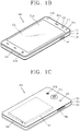
- FIGS. 1B and 1C are conceptual views of one example of the mobile terminal, viewed from different directions.
- the mobile terminal 100 is shown having components such as a wireless communication unit 110, an input unit 120, a sensing unit 140, an output unit 150, an interface unit 160, a memory 170, a controller 180, and a power supply unit 190. Implementing all of the illustrated components is not a requirement, and that greater or fewer components may alternatively be implemented.
- the mobile terminal 100 is shown having wireless communication unit 110 configured with several commonly implemented components.
- the wireless communication unit 110 typically includes one or more components which permit wireless communication between the mobile terminal 100 and a wireless communication system or network within which the mobile terminal is located.
- the wireless communication unit 110 typically includes one or more modules which permit communications such as wireless communications between the mobile terminal 100 and a wireless communication system, communications between the mobile terminal 100 and another mobile terminal, communications between the mobile terminal 100 and an external server. Further, the wireless communication unit 110 typically includes one or more modules which connect the mobile terminal 100 to one or more networks. To facilitate such communications, the wireless communication unit 110 includes one or more of a broadcast receiving module 111, a mobile communication module 112, a wireless Internet module 113, a short-range communication module 114, and a location information module 115.
- the input unit 120 includes a camera 121 for obtaining images or video, a microphone 122, which is one type of audio input device for inputting an audio signal, and a user input unit 123 (for example, a touch key, a push key, a mechanical key, a soft key, and the like) for allowing a user to input information.
- Data for example, audio, video, image, and the like
- controller 180 may analyze and process data (for example, audio, video, image, and the like) according to device parameters, user commands, and combinations thereof.
- the sensing unit 140 is typically implemented using one or more sensors configured to sense internal information of the mobile terminal, the surrounding environment of the mobile terminal, user information, and the like.
- the sensing unit 140 is shown having a proximity sensor 141 and an illumination sensor 142.
- the sensing unit 140 may alternatively or additionally include other types of sensors or devices, such as a touch sensor, an acceleration sensor, a magnetic sensor, a G-sensor, a gyroscope sensor, a motion sensor, an RGB sensor, an infrared (IR) sensor, a finger scan sensor, a ultrasonic sensor, an optical sensor (for example, camera 121), a microphone 122, a battery gauge, an environment sensor (for example, a barometer, a hygrometer, a thermometer, a radiation detection sensor, a thermal sensor, and a gas sensor, among others), and a chemical sensor (for example, an electronic nose, a health care sensor, a biometric sensor, and the like), to name a few.
- the mobile terminal 100 may be configured to utilize information obtained from sensing unit 140, and in particular, information obtained from one or more sensors of the sensing unit 140, and combinations thereof.
- the output unit 150 is typically configured to output various types of information, such as audio, video, tactile output, and the like.
- the output unit 150 is shown having a display unit 151, an audio output module 152, a haptic module 153, and an optical output module 154.
- the display unit 151 may have an inter-layered structure or an integrated structure with a touch sensor in order to facilitate a touch screen.
- the touch screen may provide an output interface between the mobile terminal 100 and a user, as well as function as the user input unit 123 which provides an input interface between the mobile terminal 100 and the user.
- the interface unit 160 serves as an interface with various types of external devices that can be coupled to the mobile terminal 100.
- the interface unit 160 may include any of wired or wireless ports, external power supply ports, wired or wireless data ports, memory card ports, ports for connecting a device having an identification module, audio input/output (I/O) ports, video I/O ports, earphone ports, and the like.
- the mobile terminal 100 may perform assorted control functions associated with a connected external device, in response to the external device being connected to the interface unit 160.
- the memory 170 is typically implemented to store data to support various functions or features of the mobile terminal 100.
- the memory 170 may be configured to store application programs executed in the mobile terminal 100, data or instructions for operations of the mobile terminal 100, and the like. Some of these application programs may be downloaded from an external server via wireless communication. Other application programs may be installed within the mobile terminal 100 at time of manufacturing or shipping, which is typically the case for basic functions of the mobile terminal 100 (for example, receiving a call, placing a call, receiving a message, sending a message, and the like). It is common for application programs to be stored in the memory 170, installed in the mobile terminal 100, and executed by the controller 180 to perform an operation (or function) for the mobile terminal 100.
- the controller 180 typically functions to control overall operation of the mobile terminal 100, in addition to the operations associated with the application programs.
- the controller 180 can provide or process information or functions appropriate for a user by processing signals, data, information and the like, which are input or output by the various components depicted in FIG. 1A , or activating application programs stored in the memory 170.
- the controller 180 controls some or all of the components illustrated in FIGS. 1A-1C according to the execution of an application program that have been stored in the memory 170.
- the power supply unit 190 can be configured to receive external power or provide internal power in order to supply appropriate power required for operating elements and components included in the mobile terminal 100.
- the power supply unit 190 may include a battery, and the battery may be configured to be embedded in the terminal body, or configured to be detachable from the terminal body.
- At least some of the above components may operate in a cooperating manner, so as to implement an operation or a control method of a glass type terminal according to various embodiments to be explained later.
- the operation or the control method of the glass type terminal may be implemented on the glass type terminal by driving at least one application program stored in the memory 170.
- another mobile terminal (which may be configured similarly to mobile terminal 100) may be a wearable device, for example, a smart watch, a smart glass or a head mounted display (HMD), which can exchange data with the mobile terminal 100 (or otherwise cooperate with the mobile terminal 100).
- the short-range communication module 114 may sense or recognize the wearable device, and permit communication between the wearable device and the mobile terminal 100.
- the control unit 180 when the sensed wearable device is a device which is authenticated to communicate with the mobile terminal 100, the control unit 180, for example, may cause transmission of data processed in the mobile terminal 100 to the wearable device via the short-range communication module 114.
- a user of the wearable device may use the data processed in the mobile terminal 100 on the wearable device. For example, when a call is received in the mobile terminal 100, the user may answer the call using the wearable device. Also, when a message is received in the mobile terminal 100, the user can check the received message using the wearable device.
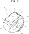
- FIG. 2 is a perspective view illustrating one example of a watch-type wearable device 200 in accordance with another exemplary embodiment.
- the watch-type wearable device 200 includes a main body 201 with a display unit 251 and a band 202 connected to the main body 201 to be wearable on a wrist.
- wearable device 200 may be configured to include features that are the same or similar to that of the mobile terminal 100 of FIGS. 1A to 1C .
- the main body 201 may include a case having a certain appearance. As illustrated, the case may include a first case 201a and a second case 201b cooperatively defining an inner space for accommodating various electronic components. Other configurations are possible. For instance, a single case may alternatively be implemented, with such a case being configured to define the inner space, thereby implementing a watch-type wearable device 200 with a uni-body.
- the watch-type wearable device 200 can perform wireless communication, and an antenna for the wireless communication can be installed in the main body 201.
- the antenna may extend its function using the case.
- a case including a conductive material may be electrically connected to the antenna to extend a ground area or a radiation area.
- the display unit 251 is shown located at the front side of the main body 201 so that displayed information is viewable to a user.
- the display unit 251 includes a touch sensor so that the display unit can function as a touch screen.
- window 251a is positioned on the first case 201a to form a front surface of the terminal body together with the first case 201 a.
- the illustrated embodiment includes audio output module 252, a camera 221, a microphone 222, and a user input unit 223 positioned on the main body 201.
- audio output module 252 When the display unit 251 is implemented as a touch screen, additional function keys may be minimized or eliminated.
- the user input unit 223 may be omitted.
- the band 202 is commonly worn on the user's wrist and may be made of a flexible material for facilitating wearing of the device.
- the band 202 may be made of fur, rubber, silicon, synthetic resin, or the like.
- the band 202 may also be configured to be detachable from the main body 201. Accordingly, the band 202 may be replaceable with various types of bands according to a user's preference.
- the band 202 may be used for extending the performance of the antenna.
- the band may include therein a ground extending portion electrically connected to the antenna to extend a ground area.
- the band 202 may include fastener 202a.
- the fastener 202a may be implemented into a buckle type, a snap-fit hook structure, a Velcro® type, or the like, and include a flexible section or material.
- the drawing illustrates an example that the fastener 202a is implemented using a buckle.
- Such communication systems utilize different air interfaces and/or physical layers.
- air interfaces utilized by the communication systems include Frequency Division Multiple Access (FDMA), Time Division Multiple Access (TDMA), Code Division Multiple Access (CDMA), and Universal Mobile Telecommunications System (UMTS), the Long Term Evolution (LTE) of the UMTS, the Global System for Mobile Communications (GSM), and the like.
- FDMA Frequency Division Multiple Access
- TDMA Time Division Multiple Access
- CDMA Code Division Multiple Access
- UMTS Universal Mobile Telecommunications System
- LTE Long Term Evolution
- GSM Global System for Mobile Communications
- a CDMA wireless communication system is shown having a plurality of mobile terminals 100, a plurality of base stations (BSs), base station controllers (BSCs), and a mobile switching center (MSC).
- the MSC is configured to interface with a conventional Public Switch Telephone Network (PSTN).
- PSTN Public Switch Telephone Network
- the MSC is also configured to interface with the BSCs.
- the BSCs are coupled to the base stations via backhaul lines.
- the backhaul lines may be configured in accordance with any of several known interfaces including, for example, E1/T1, ATM, IP, PPP, Frame Relay, HDSL, ADSL, or xDSL.
- the plurality of BSCs can be included in the system.
- Each base station may include one or more sectors, each sector having an omni-directional antenna or an antenna pointed in a particular direction radially away from the base station. Alternatively, each sector may include two or more different antennas. Each base station may be configured to support a plurality of frequency assignments, with each frequency assignment having a particular spectrum (e.g., 1.25 MHz, 5 MHz, etc.).
- the intersection of sector and frequency assignment may be referred to as a CDMA channel.
- the base stations may also be referred to as Base Station Transceiver Subsystems (BTSs).
- BTSs Base Station Transceiver Subsystems
- the term "base station” may be used to refer collectively to a BSC, and one or more base stations.
- the base stations may also be denoted as "cell sites.” Alternatively, individual sectors of a given base station may be referred to as cell sites.
- a broadcasting transmitter transmits a broadcast signal to the mobile terminals 100 operating within the system.
- the broadcast receiving module 111 is typically configured inside the mobile terminal 100 to receive broadcast signals transmitted by the BT.
- GPS satellites 300 facilitate locating the position of at least one of plural mobile terminals 100. Useful position information may be obtained with greater or fewer satellites than two satellites. It is to be appreciated that other types of position detection technology, (i.e., location technology that may be used in addition to or instead of GPS location technology) may alternatively be implemented. If desired, at least one of the GPS satellites 300 may alternatively or additionally be configured to provide satellite DMB transmissions.
- GPS Global Positioning System
- the location information module 115 is generally configured to detect, calculate, or otherwise identify a position of the mobile terminal.
- the location information module 115 may include a Global Position System (GPS) module, a Wi-Fi module, or both. If desired, the location information module 115 may alternatively or additionally function with any of the other modules of the wireless communication unit 110 to obtain data related to the position of the mobile terminal.
- GPS Global Position System
- Wi-Fi Wireless Fidelity
- a typical GPS module 115 can measure an accurate time and distance from three or more satellites, and accurately calculate a current location of the mobile terminal according to trigonometry based on the measured time and distances.
- a method of acquiring distance and time information from three satellites and performing error correction with a single satellite may be used.
- the GPS module may acquire an accurate time together with three-dimensional speed information as well as the location of the latitude, longitude and altitude values from the location information received from the satellites.
- the GPS module can acquire speed information in real time to calculate a current position.
- accuracy of a measured position may be compromised when the mobile terminal is located in a blind spot of satellite signals, such as being located in an indoor space.
- an alternative or supplemental location technique such as Wi-Fi Positioning System (WPS) may be utilized.
- WPS Wi-Fi Positioning System
- the Wi-Fi positioning system refers to a location determination technology based on a wireless local area network (WLAN) using Wi-Fi as a technology for tracking the location of the mobile terminal 100.
- This technology typically includes the use of a Wi-Fi module in the mobile terminal 100 and a wireless access point for communicating with the Wi-Fi module.
- the Wi-Fi positioning system may include a Wi-Fi location determination server, a mobile terminal, a wireless access point (AP) connected to the mobile terminal, and a database stored with wireless AP information.
- the mobile terminal connected to the wireless AP may transmit a location information request message to the Wi-Fi location determination server.
- the Wi-Fi location determination server extracts the information of the wireless AP connected to the mobile terminal 100, based on the location information request message (or signal) of the mobile terminal 100.
- the information of the wireless AP may be transmitted to the Wi-Fi location determination server through the mobile terminal 100, or may be transmitted to the Wi-Fi location determination server from the wireless AP.
- the information of the wireless AP extracted based on the location information request message of the mobile terminal 100 may include one or more of media access control (MAC) address, service set identification (SSID), received signal strength indicator (RSSI), reference signal received Power(RSRP), reference signal received quality(RSRQ), channel information, privacy, network type, signal strength, noise strength, and the like.
- MAC media access control
- SSID service set identification
- RSSI received signal strength indicator
- RSRP reference signal received Power
- RSRQ reference signal received quality
- channel information privacy, network type, signal strength, noise strength, and the like.
- the Wi-Fi location determination server may receive the information of the wireless AP connected to the mobile terminal 100 as described above, and may extract wireless AP information corresponding to the wireless AP connected to the mobile terminal from the preestablished database.
- the information of any wireless APs stored in the database may be information such as MAC address, SSID, RSSI, channel information, privacy, network type, latitude and longitude coordinate, building at which the wireless AP is located, floor number, detailed indoor location information (GPS coordinate available), AP owner's address, phone number, and the like.
- the Wi-Fi location determination server may extract only a predetermined number of wireless AP information in order of high RSSI. Then, the Wi-Fi location determination server may extract (analyze) location information of the mobile terminal 100 using at least one wireless AP information extracted from the database.
- a method for extracting (analyzing) location information of the mobile terminal 100 may include a Cell-ID method, a fingerprint method, a trigonometry method, a landmark method, and the like.
- the Cell-ID method is used to determine a position of a wireless AP having the largest signal strength, among peripheral wireless AP information collected by a mobile terminal, as a position of the mobile terminal.
- the Cell-ID method is an implementation that is minimally complex, does not require additional costs, and location information can be rapidly acquired. However, in the Cell-ID method, the precision of positioning may fall below a desired threshold when the installation density of wireless APs is low.
- the fingerprint method is used to collect signal strength information by selecting a reference position from a service area, and to track a position of a mobile terminal using the signal strength information transmitted from the mobile terminal based on the collected information.
- the trigonometry method is used to calculate a position of a mobile terminal based on a distance between coordinates of at least three wireless APs and the mobile terminal.
- signal strength may be converted into distance information, Time of Arrival (ToA), Time Difference of Arrival (TDoA), Angle of Arrival (AoA), or the like may be taken for transmitted wireless signals.
- ToA Time of Arrival
- TDoA Time Difference of Arrival
- AoA Angle of Arrival
- the landmark method is used to measure a position of a mobile terminal using a known landmark transmitter.
- various algorithms may be used to extract (analyze) location information of a mobile terminal. Such extracted location information may be transmitted to the mobile terminal 100 through the Wi-Fi location determination server, thereby acquiring location information of the mobile terminal 100.
- the mobile terminal 100 can acquire location information by being connected to at least one wireless AP.
- the number of wireless APs required to acquire location information of the mobile terminal 100 may be variously changed according to a wireless communication environment within which the mobile terminal 100 is positioned.
- the mobile terminal may be configured to include short-range communication techniques such as BluetoothTM, Radio Frequency Identification (RFID), Infrared Data Association (IrDA), Ultra Wideband (UWB), ZigBee, Near Field Communication (NFC), Wireless USB (Wireless Universal Serial Bus), and the like.
- RFID Radio Frequency Identification
- IrDA Infrared Data Association
- UWB Ultra Wideband
- ZigBee Near Field Communication
- NFC Near Field Communication
- Wireless USB Wireless Universal Serial Bus
- a typical NFC module provided at the mobile terminal supports short-range wireless communication, which is a non-contactable type of communication between mobile terminals and generally occurs within about 10 cm.
- the NFC module may operate in one of a card mode, a reader mode, or a P2P mode.
- the mobile terminal 100 may further include a security module for storing card information, in order to operate the NFC module in a card mode.
- the security module may be a physical medium such as Universal Integrated Circuit Card (UICC) (e.g., a Subscriber Identification Module (SIM) or Universal SIM (USIM)), a secure micro SD and a sticker, or a logical medium (e.g., embedded Secure Element (SE)) embedded in the mobile terminal.
- SIM Subscriber Identification Module
- USIM Universal SIM
- SE embedded Secure Element
- the mobile terminal may transmit card information on a general IC card to the outside. More specifically, if a mobile terminal having card information on a payment card (e. g, a credit card or a bus card) approaches a card reader, a short-range mobile payment may be executed. As another example, if a mobile terminal which stores card information on an entrance card approaches an entrance card reader, an entrance approval procedure may start.
- a card such as a credit card, a traffic card, or an entrance card may be included in the security module in the form of applet, and the security module may store card information on the card mounted therein.
- Card information for a payment card may include any of a card number, a remaining amount and usage history, and the like.
- Card information of an entrance card may include any of a user's name, a user's number (e.g., undergraduate number or staff number), an entrance history, and the like.
- the mobile terminal can read data from an external tag.
- the data received from the external tag by the mobile terminal may be coded into the NFC Data Exchange Format defined by the NFC Forum.
- the NFC Forum generally defines four record types. More specifically, the NFC Forum defines four Record Type Definitions (RTDs) such as smart poster, text, Uniform Resource Identifier (URI), and general control.
- RTDs Record Type Definitions
- the controller may execute a browser (e.g., Internet browser).
- the controller may execute a text viewer.
- the controller may execute a browser or originate a call.
- the controller may execute a proper operation according to control content.
- the mobile terminal can execute P2P communication with another mobile terminal.
- Logical Link Control Protocol (LLCP) may be applied to the P2P communication.
- LLCP Logical Link Control Protocol
- connection may be generated between the mobile terminal and another mobile terminal. This connection may be categorized as a connectionless mode which ends after one packet is switched, and a connection-oriented mode in which packets are switched consecutively.
- data such as an electronic type name card, address information, a digital photo and a URL, a setup parameter for Bluetooth connection, Wi-Fi connection, etc. may be switched.
- the P2P mode can be effectively utilized in switching data of a small capacity, because an available distance for NFC communication is relatively short.
- the GPS (Global Position System) module, the WiFi (Wireless Fidelity) module, and the NFC module described above may be applied to a watch type mobile terminal 200, and may also be applied to at least one of a main system 310, a FOB module 380, and a display 370 described hereinafter. In other words, at least one of the components described above may be included in (or applied to) the watch type mobile terminal 200 of the present disclosure.
- the present disclosure relates to a watch type mobile terminal and may include at least one component discussed above with reference to FIGS. 1A to 2 .
- a watch type mobile terminal according to an embodiment of the present disclosure will be described in detail.
- FIGS. 3A , 3B , and 3C are conceptual views illustrating a watch type mobile terminal according to an embodiment of the present disclosure.
- a watch type mobile terminal according to an embodiment of the present disclosure includes a FOB module capable of controlling a vehicle.
- the FOB module has a function of controlling a vehicle (or a function related to a vehicle). For example, when a user input is received through a display unit or a user input unit provided in a watch type mobile terminal, a vehicle can be controlled to perform a function related to the vehicle corresponding to the input.
- the watch type mobile terminal including the FOB module can be coupled to the band 202 described above with reference to FIG. 2 so as to be used. Further, the watch type mobile terminal related to the present disclosure can serve as an electronic key for a vehicle or a smart vehicle key.
- the FOB module can perform various functions provided in a smart key for an existing vehicle.
- the FOB module can perform a vehicle door opening and closing function, a trunk opening and closing function, an emergency lamp lighting function, a Klaxon (horn) output function, an immobilizer function, and the like.
- the FOB module can differentially set a control authority of the vehicle.
- the control authority of the vehicle can be set when the FOB module is attached to a main system, or when the FOB module is separated from the main system, the control authority of the vehicle can be set through user authentication or through a previously authenticated external terminal (for example, a mobile terminal owned by the user of the watch type mobile terminal or a mobile terminal which has performed with the watch type mobile terminal).
- the watch type mobile terminal can be termed a "FOB key", an "immobilizer key”, an "electronic key”, a “smart key”, a "card key”, or the like.
- FIG. 3A is a block diagram illustrating a configuration of a watch type mobile terminal according to an embodiment of the present disclosure.
- the watch type mobile terminal 200 according to an embodiment of the present disclosure includes a main system 310 (or a main module or a main system module) formed as a module or a board and electrically or physically detachably attached to the FOB module described above (see FIG. 3B ).
- the main system 310 includes a signal processing unit 311, an interface unit 320, a communication unit 330, a memory 340, a smart key controller 350, and a power supply unit 360.
- the signal processing unit 311 (or the controller 180) processes a signal transferred between components of the main system 310.
- the main system 310 may include at least one of the components described above with reference to FIG. 1A , and the signal processing unit 311 may be, for example, the controller 180 described above with reference to FIG. 1A .
- the interface unit 320 can be connected to a vehicle controller provided in the vehicle such that it performs wired/wireless communication with the vehicle controller.
- the interface unit 320 includes at least one button associated with a function related to the vehicle, and can receive a user command through each button. Further, the interface unit 320 can deliver a user command received through a button to the smart key controller 350 through the signal processing unit 311.
- the interface unit 320 can be connected to the vehicle controller (or a vehicle driving unit) wiredly or wirelessly, and can be connected to the FOB module 380 such that it performs wired/wireless communication with the FOB module 380.
- the interface unit 320 transmits the received signal to the vehicle controller.
- the interface unit 320 delivers the ignition start signal to the vehicle controller such that the engine of the vehicle is started.
- the interface unit 320 may be the interface unit 160 described above with reference to FIG. 1A .
- the communication unit 330 includes a communication module supporting a communication interface unit for signal transmission and reception with the FOB module 380.
- the communication unit 330 can have a low frequency (LF) communication unit 331 transmitting an LF signal having a preset frequency band, for example, 125 kHz, 134 kHz, or the like, to the FOB module 380, and a radio frequency (RF) communication unit 332 receiving an RF signal having a preset frequency band, for example, 433 MHz, or the like, from the FOB module 380.
- LF low frequency
- RF radio frequency
- the communication unit 330 can further include a communication module supporting a communication interface unit for signal transmission and reception with a neighbor mobile terminal 100.
- the communication unit 330 can have a short-range communication unit 333 transmitting and receiving a signal to and from a mobile terminal through a communication scheme such as near field communication (NFC), Bluetooth, and the like.
- NFC near field communication
- Bluetooth and the like.
- the communication unit 330 may be the wireless communication unit 110 described above with reference to FIG. 1A .
- a communication unit 110 can also be provided in the FOB module 380 and/or the display unit 370, as well as in the main system 310 of the present disclosure.
- the memory 340 can store a set value for an operation of the main system 310 such as frequency information of a signal of the FOB module 380 defined for signal transmission and reception with the FOB module 380.
- the memory 340 may include information related to a control authority to control a vehicle and information related to user authentication.
- the memory 340 can store a control algorithm generating a control command for controlling driving of a vehicle using a signal received from the FOB module 380.
- the memory 340 can also store information set for signal transmission and reception with the mobile terminal 100, and store a control algorithm for controlling power level of the mobile terminal 100.
- the memory 340 may be the memory 170 described above with reference to FIG. 1A .
- the smart key controller 350 When a function provided in the vehicle is executed, the smart key controller 350 receives a signal related to the executed function through the interface unit 220, generates a driving signal (wake-up) driving the FOB module 380, and transmits the driving signal to the FOB module 280 through the LF communication unit 331.
- the smart key controller 350 determines that authentication of the corresponding FOB module 380 has been successfully performed. Thereafter, the smart key controller 350 transmits the control command, which has been input through the interface unit 320, to the FOB module 380 through the LF communication unit 331.
- the smart key controller 350 can output a command for driving a corresponding driving unit of the vehicle through the interface unit 220 based on the start signal.
- the smart key controller 350 determines that authentication of the corresponding FOB module 380 has failed.
- the smart key controller 350 is a separate component, but the present disclosure is not limited thereto. Every component/function/features performed by the smart key controller 350 can be performed by the signal processing unit 311 (or the controller 180).
- the power supply unit 360 supplying power to the watch type mobile terminal 200 is provided.
- the power supply unit 360 may be a battery 360 which is installed in the watch type mobile terminal 200 or detachably formed in the watch type mobile terminal 200.
- the power supply unit 360 may be the power supply unit 190 described above with reference to FIG. 1A .
- the battery can receive power through a power cable connected to the interface unit 320 or be wirelessly charged through a wireless charging device.
- Wireless charging can be implemented through electromagnetic inductive coupling or magnetic resonance.
- the FOB module 380 includes a processor or controller 382, an input unit 381, a communication unit 383, a reading unit 386, and a storage unit 387.
- the processor 382 (or controller) controls an operation of each component of the FOB module 380.
- At least one operation button can be provided in the FOB module 380, and a command corresponding to a button operated in the FOB module 380 can be input through the input unit 381.
- the communication unit 383 includes a communication module supporting a communication interface for signal transmission and reception with the main system 310.
- the communication unit 383 can have an LF communication unit 384 receiving an LF signal having a preset frequency band, for example, 125 kHz, 134 kHz, and the like, from the main system 310, and can have an RF communication unit 385 transmitting an RF signal having a preset frequency band, for example, 433 MHz, or the like, to the smart key main system 310.
- the communication unit 383 can be the wireless communication unit 110 described above with reference to FIG. 1A .
- the reading unit 386 reads a signal received through the LF communication unit 284.
- the reading unit 386 can read a driving signal received through the LF communication unit 384, and when authentication of the FOB module 380 is completed, the reading unit 386 can read a request signal received through the LF communication unit 384.
- the processor 382 can generate a corresponding response signal according to a reading result from the reading unit 386, and transmit the generated response signal to the main system 310 through the RF communication unit 385. Further, the processor 382 can compare the reading result from the reading unit 3386 with data stored in the storage unit 387 and generate a response signal according to the comparison result.
- the processor 382 can compare the reading result from the reading unit 386 with data stored in the storage unit 387. When the reading result and the data match, the processor 382 generates a response signal for acknowledging the driving signal and transmits the response signal to the main system 310. In addition, when the reading result from the reading unit 386 and the data stored in the storage unit 387 does not match, the processor 382 determines that an error has occurred, and transmits an error signal to the main system 310.
- a communication set value for signal transmission and reception between the FOB module 380 and the main system 310 can be stored in the storage unit 387, and information for signal generation can be stored in the storage unit 387.
- the display unit 370 (or a display module) displays (outputs) information processed in at least one of the FOB module 380 and the main system 310.
- the display unit 370 can display execution screen information of an application program driven in at least one of the FOB module 380 and the main system 310 or user interface (UI) or graphic user interface (GUI) information in accordance with such execution screen information.
- the display unit 370 can be configured as a stereoscopic display unit displaying a stereoscopic image.
- Three-dimensional (3D) display method such as a stereoscopic method (glass type), an auto-stereoscopic method (glassless type), a projection method (holographic type), and the like, can be applied to the stereoscopic display unit
- FIG. 3B is a perspective view and an exploded perspective view of a watch type mobile terminal according to an embodiment of the present disclosure.
- a main body 300 or 201 of the watch type mobile terminal according to an embodiment of the present disclosure can include a FOB module 380 formed to control a vehicle.
- the main body 300 of the watch type mobile terminal includes a display unit 370, the FOB module 380, the main system 310, the power supply unit 360, and the main frame 390.
- the main frame 390 can be at least one of the first case 201a and the second case 201b described above with reference to FIG. 2 , or a combination thereof.
- the main frame 390 serves as a case allowing at least one of the display unit 370, the FOB module 380, the main system 310, and the power supply unit (battery) 360 to be coupled. Also, the band 202 described above with reference to FIG. 2 can be coupled to the main frame 390.
- FIG. 3B illustrates the main body 300 of the watch type mobile terminal 200 has a circular shape, but, without being limited thereto, the main body 300 can also have an oval shape or a polygonal shape.
- the main body 300 of the watch type mobile terminal according to an embodiment of the present disclosure having the aforementioned configuration can be integrally formed (first type), or at least one of the display unit 370, the FOB module 380, and the main system 310 among the components of the watch type mobile terminal can be separately formed to be independently used (operated).
- the display unit can be separately used (second type) from the other remaining components
- the display unit and the FOB module can be integrally formed and separately used (third type) from the other remaining components
- the FOB module can be selectively coupled to the display unit or the main system and used (fourth type).
- the display unit can be used alone, the display unit and the FOB module can be formed as a single module (or coupled) and separately used from the main system 310, or the display unit, the FOB module, and the main system 310 can be individually separated to be used.
- the components have a communication unit (for example, the wireless communication unit 110 of FIG. 1A ) to perform communication with each other.
- the watch type mobile terminal 200 can interwork with another mobile terminal, e.g., a smartphone, so as to be used.
- a mobile communication terminal and a vehicle can perform wireless communication in an LF and RF communication manner using a mobile communication network
- the watch type mobile terminal 200 and the other mobile terminal can perform wireless communication in a Bluetooth communication manner.
- the other mobile terminal can be a smartphone in which a dedicated application associated with various functional operation units of a vehicle in an internal system thereof, and the dedicated application is driven.
- the smartphone as the mobile terminal described above with reference to FIGS. 1A to 1C , can be any wireless communication device as long as it can perform wireless communication such as a mobile communication network or Bluetooth communication such as a mobile phone, a notebook computer, a digital broadcasting terminal, a personal digital assistant (PDA), a portable multimedia player (PMP), and any other table PCs.
- a mobile communication network such as a mobile phone, a notebook computer, a digital broadcasting terminal, a personal digital assistant (PDA), a portable multimedia player (PMP), and any other table PCs.
- PDA personal digital assistant
- PMP portable multimedia player
- the other mobile terminal will be referred to as a "smartphone", an "external device”, an “external terminal”, or a "preset external terminal”.
- the FOB module 380 can be any module as long as it can perform wireless communication with a smart key control unit provided in a vehicle and apply a predetermined electrical signal, regardless of type such as a FOB key or a card type key as described above.
- the first to fourth types are classified according to selective coupling of the detachable FOB module 380. That is, the FOB module 380 can be coupled to the display unit 370 and the main system 310 so a to be used. Thus, a connector is provided above or below the FOB module 380, and a connection terminal electrically connected to the FOB module is provided above the main system 310.
- the first type can be, for example, when the FOB module is installed in a band and used.
- the watch type mobile terminal When used as the first type, operates like a general smart watch and has the same appearance as that of the smart watch.
- the second type can be, for example, when only the display unit 370 is separated and the FOB module 380 and the main system 310 can be coupled and connected together with a band such that the display unit 380 is installed in a preset external terminal.
- the display unit 370 can be disposed on (coupled or attached to) a rear surface of the preset external terminal to provide a display unit, different from a front display unit provided on a front side of the terminal body, to a rear side of the terminal body.
- the display unit provided on the preset external terminal will be referred to as a first display unit and the display unit 380 provided on the watch type mobile terminal 200 will be referred to as a second display unit.
- the second display unit provided on the rear side of the mobile communication terminal has a small size, and thus can simply display information regarding a user or a vehicle. Further, the second display unit can input information based on a touch, like the first display unit.
- the FOB module 380 coupled to the band can be used without a display, and simple information can be output by an output unit other than the second display unit.
- the watch type mobile terminal 200 can serve as an activity tracker.
- the watch type mobile terminal 200 without the display unit can be simply used as a pedometer or can perform a healthcare function by a heart rate sensor, or the like.
- the FOB module 380 is coupled to the band, it is possible to control an external device (vehicle).
- the third type is when the second display unit 370 is coupled to the FOB module 380 and the FOB module 380 and the main system 310 are separately used.
- the FOB module 380 and the display unit 370 separated from the main system 310 can be installed on a rear surface of a preset external terminal so as to be used.
- an external device can be controlled through the preset external terminal.
- a series of information and a user information controlling the external device can also be displayed on the second display unit 370.
- the external device can be controlled.
- a function of controlling the external device (vehicle) provided in the FOB module 380 can also be provided in the main system 310.
- the FOB module 380 is separated from the main system 310, the user can perform controlling on the external device (vehicle) using the main system 310.
- control authorities can be set in the FOB module 380 and the main system 310.
- a first control authority for performing only a predetermined function provided in an external device can be set in the FOB module 380
- a second control authority, higher than the first control authority, for performing every function provided in an external device can be set in the main system 310.
- the main system 310 coupled to the band can perform only a predetermined function such as an activity tracker.
- the fourth type can be a type in which the display unit 370, the FOB module 380, and the main system 310 are all separable, and can be a type which can be individually used.
- the FOB module 380 can be coupled to the main system 310 so as to be used, and can be coupled to the display unit 370 so as to be used, or can be used autonomously.
- the fourth type can be when an installation position of the FOB module 380 is selectively switchable.
- the FOB module 380 When the FOB module 380 is coupled to the main system and used, it can be similar to the second type described above, and when the FOB module is coupled to the second display unit and used, it can be similar to the case of the third type described above.
- a battery and a predetermined processor can be provided in each of the display unit 370 and the FOB module 380 such that at least one of the display unit 370 and the FOB module 380 can be separated and used according to the second to fourth types. Also, the display unit 370, the FOB module 380, and the main system 310 can each have a wireless communication unit 110 to communicate with each other.
- FIG. 4 is a circuit diagram of a watch type mobile terminal according to an embodiment of the present disclosure.
- the watch type mobile terminal 200 related to the present disclosure can include a band 202 worn on a user's wrist to surround the wrist, a main frame 390 connected to the band 202, a main system 310 provided in the main frame 390, a FOB module 380 formed to be detachably attached to the main system, and a display unit 370 formed to be detachable from the FOB module 380.
- the main system 310 can include a flash memory, an LED module, a short-range communication module (Bluetooth0, a sensor, a motor driver, a power management integrated circuit (PMIC), a charging module (charger), an input unit (buttons), and an MCU (controller). These components can be at least one of the components described above with reference to FIGS. 1A to 1C .
- the display unit 370 (or a display module) can include an LCD module, a touch screen controller, and the like.
- the FOB module 380 can include an immobilizer, an MCU, an LF reception unit, an RF transmission unit, a capacitor, a flash memory, and the like.
- the main system 310 and the display unit 370 can each have a connector to be electrically connected to the FOB module 380.
- a first connector to electrically connected with the main system 310 can be provided on one surface of the FOB module 380, and a second connector to be electrically connected to the display unit 370 can be provided on the other surface opposing the one surface of the FOB module 380.
- “coupling (connecting or attaching) a component A and a component B” can refer to electrical coupling the component A and the component B, as well as physical coupling the component A and component B.
- separating the component A and the component B can refer to “ electrically separating the component A and the component B, as well as physically separating the component A and the component B.
- the component A and the component B can be at least one of the main system 310, the display unit 370, and the FOB module 380 include din the watch type mobile terminal of the present disclosure.
- serial communication technique such as a serial peripheral interface (SPI) communication technique and an inter-integrated circuit (I2C) communication technique in an embodiment of the present disclosure.
- SPI serial peripheral interface
- I2C inter-integrated circuit
- the main system 310, the FOB module 380, and the display unit 370 can have a wireless communication unit.
- the wireless communication unit can be the wireless communication unit described above with reference to FIG. 1A , for example.
- the coupled components can perform communication through a connector.
- the separated modules can perform wireless communication through the wireless communication unit.
- Each of the FOB module 380 and the display unit 370 can be formed to be detachably attached to an external device.
- an external device can have a connector, and the connector of the external device can be connected to a first connector (or second connector) of the FOB module 380 or can be connected to a connector of the display unit 380. Also, the external device and the FOB module 380 or the external device and the display unit 370 can be physically attached.
- the external device can include any type electronic device which can communicate with the watch type mobile terminal of the present disclosure.
- the external device can be the external device ( FIGS. 1A to 1C ) or a vehicle.
- a control authority for controlling the external device can be set in at least one of the main system 310, the FOB module 380, and the display unit 370.
- the external device can be controlled based on attachment of a module separated from the watch type mobile terminal 200 or through wireless communication with the separated module.
- the main system 310 and the FOB module 380 can be coupled and the FOB module 380 can be coupled to the display unit 370, but the present disclosure is not limited thereto.
- the display unit 370 can be detachably attached to the main system 310. Further, only the FOB module 380 can be separated and the display unit 370 and the main system 310 can be coupled. In this instance, the display unit 370 and the main system 310 can be electrically connected through a connector of the display unit 370 and a connector of the main system 310, and the FOB module 380 separated from the main system 310 (or the display unit 370) can perform wireless communication through a wireless communication unit.
- a type performed through this coupling can be defined as a "fifth type.” That is, as illustrated in FIG. 3C , the watch type mobile terminal related to the present disclosure can operate in at least one of the first type in which all the main system 310, the FOB module 380, and the display unit 370 are coupled, the second type I which the main system 310 and the FOB module 380 are coupled and the display unit 370 is separated from the FOB module, the third type in which the FOB module 380 and the display unit 370 are coupled and the FOB module 380 is separated from the main system 310, and the fourth type in which all of the main system 310, the FOB module 380, and the display unit 370 are separated. Also, the watch type mobile terminal related to the present disclosure can also be operated in the fifth type in which only the FOB module 380 is separated and the main system 310 and the display unit 370 are coupled.
- FIG. 5 is a conceptual view illustrating an external device to which a module separated from a watch type mobile terminal according to an embodiment of the present disclosure is attached.
- an external device 500 as an embodiment of an external device is illustrated.
- the external terminal 500 can be the mobile terminal described above with reference to FIGS. 1A to 1C .
- the external terminal 500 (mobile terminal 100) can have at least one connector 510 and 520 (or Appsport) to which an external module is attachable.
- the connector is in plurality, the plurality of connectors can be implemented to be connected by a circuit board (e.g., a flexible printed circuit board (FPCB)) such that they communicate with each other.
- a circuit board e.g., a flexible printed circuit board (FPCB)
- the FOB module 380 or the display unit 370 separated from the watch type mobile terminal 200 related to the present disclosure can be connected to the external terminal 500. Further, the FOB module 380 can have different control authorities according to a type (or position) of a coupled connector among a plurality of connectors provided in the external terminal.
- a first control authority for controlling an external device can be set in the FOB module 380, and when the FOB module 380 is coupled to a second connector 520 different from the first connector 510 of the external terminal, a second control authority different from the first control authority can be set.
- the display unit 370 can display different types of screen information according to a type (or position) of coupled connector among a plurality of connectors provided in the external terminal. For example, when the display unit 370 is coupled or connected to the first connector of the external terminal, the display unit 370 can display first screen information, and when the display unit 370 is coupled or connected to a second connector different from the first connector of the external terminal, the display unit 370 can output second screen information different from the first screen information.
- the watch type mobile terminal related to the present disclosure can perform different functions according to whether the FOB module 380 or the display unit 370 is individually attached to an external device (external terminal 500) or whether the FOB module 380 and the display unit 370 in a coupled state is attached to the external device (external terminal 500).
- the FOB module 380 when the FOB module 380 is attached to the external terminal 500, the FOB module 380 can perform a first function, and when the display unit 370 is attached to the external terminal, the display unit 370 can perform a second function different from the first function. Also, when the FOB module 380 and the display unit 370 in a coupled state are attached to the external terminal 500, a third function different from the first and second functions can be performed.
- the first to third functions can include a control authority, screen information, a control method, and the like, and the first to third functions may not be always different but at least one thereof may be the same/similar function.
- the FOB module 380 can be selectively coupled to any one of the main system 310 and the display unit 370.
- a control authority of an external device e.g., a vehicle granted to (or set in) the FOB module 380 can be varied.
- a first control authority can be granted.
- a second control authority different from the first control authority can be granted.
- the first control authority set in (or granted to) the FOB module 380 can be a control authority to control every function of a vehicle.
- the second control authority set in (or granted to)the FOB module 380 can be a control authority to limit a predetermined function or a predetermined operation of a vehicle. For example, when the second control authority is set in a second main body, opening of a specific box of a vehicle can be limited, some of functions of vehicle navigation can be limited, or a driving speed, a driving range, and the like, of the vehicle can be limited.
- the control authority can also be set in (or granted to) the main system 310 or the display unit 370, as well as being set in (or granted to) the FOB module 380. Also, the main system 310 can change a control authority set in the separated FOB module 380 or the display unit 370 or nullify the same. Such a change or nullification of the control authority can be performed through a wireless communication unit.
- screen information related to the vehicle can be displayed on the display unit 370.
- screen information related to the external terminal can be displayed on the display unit 370.
- Such screen information can be displayed on the display unit 370 under the control of a controller of the external device or can be displayed on the display unit 370 under the control of a processor included in the display unit 370.
- screen information related to the watch type mobile terminal 200 can be displayed on the display unit 370.
- the screen information related to the watch type mobile terminal 200 can be screen information related to a function that can be performed in the main system 310 or the FOB module 380.
- the screen information related to the watch type mobile terminal 200 can be transmitted to the display unit 370 (or the external device) from the main system 310 or the FOB module 380 through a wireless communication unit, or can be previously stored in a memory of the display unit 370.
- the watch type mobile terminal 200 related to the present disclosure can display information related to information sensed through the sensing unit 140 provided in the watch type mobile terminal 200, on at least one of a touch screen of the external device and the display unit 370 attached to the external device.
- FIG. 6 is a flow chart illustrating a control method according to an embodiment of the present disclosure
- FIGS. 7A and 7B are conceptual views illustrating the control method of FIG. 6 .
- the display unit 370 being separated from the FOB module 380 is sensed (S610).
- a controller of the main system 310 or a processor of the FOB module 380 can sense that the display unit 370 is separated from the FOB module 380 by a user.
- at least one of the FOB module 380 and the main system 310 can include the sensing unit 140 described above with reference to FIG. 1A , and the controller of the main system 310 or the processor of the FOB module 380 can sense that the display unit 370 is separated, through the sensing unit 140.
- the sensing unit 140 provided in the watch type mobile terminal i.e., the sensing unit 140 provided in at least one of the FOB module 380 and the main system 310 (S620).
- a type of the sensed information can vary according to a type of a sensor provided in the sensing unit 140.
- the processor of the display unit 370 can transmit information indicating that the display unit 370 has been attached to the external terminal 500, to the processor of the FOB module 380 or the controller of the main system 310 through a wireless communication unit.
- the processor of the display unit 370 can transmit information related to a type of the external terminal 500 to which the display unit 370 is attached, identification information, and a type (or a position) of a connector attached in the external terminal 500, to the FOB module 380 or the main system 310 through the wireless communication unit.
- information related to the information sensed by the sensing unit 140 can be displayed in at least one of the display unit 370 attached to the external terminal 500 and a touch screen of the external terminal 500 (S630).
- the controller of the main system 310 or the processor of the FOB module 380 can switch the sensing unit 140 from a deactivated state to an activated state.
- the processor of the FOB 380 can sense information through the sensing unit 140.
- the processor of the FOB module 380 can determine (or extract or sense) a state of the user who wears the watch type mobile terminal 200 based on the sensed information.
- the processor of the FOB module 380 (or the controller of the main system 310) can transmit the determined state information of the user to at least one of the external terminal 500 and the display unit 370 through the wireless communication unit.
- the controller of the external terminal 500 can determine an application program (application) to be executed and execute the determined application program, based on the received state information of the user.
- the processor of the FOB module 380 (or the controller of the main system 310) can transmit the sensed information (data) to at least one of the external terminal 500 and the display unit 370 through the wireless communication unit. Thereafter, information 700a, 700b, and 700c related to the sensed information can be displayed on at least one of the display unit 370 and the touch screen 551 of the external terminal 500.
- the information related to the sensed information can be screen information reflecting the sensed information in an execution screen of the executed application program (application).
- the information 700a displayed on the display unit 370 and the screen information 700b and 700c output on a touch screen 551 of the external terminal 500 can be different. This is because a position and a size in which the display unit 370 is attached and a position and a size of the touch screen 551 of the external terminal 500 can be different.
- the watch type mobile terminal of the present disclosure when the display unit 370 is separated and attached to an external terminal, information (screen information) related to information sensed through the sensing unit provided in the watch type mobile terminal can be displayed in at least one of the display unit 370 and the touch screen 551 of the external terminal, providing a new type mobile terminal.
- a control authority to control an external device can be set in the display unit 370.
- the display unit 370 in which a control authority is set is separated form the FOB module 380 of the watch type mobile terminal 200 and attached to the external terminal 500 as illustrated in (a) of FIG. 7B
- screen information 710a and 710b for controlling the external device can be displayed on the touch screen 551 of the external terminal 500 and the display unit 370 attached to the external terminal 500.
- the screen information 710a and 710b can be varied according to a control authority set in the display unit 370, and the screen information 710b displayed on the touch screen 551 and the screen information 710a displayed on the display unit 370 can be different.
- the screen information 710b displayed on the touch screen 551 can include a plurality of (various types of) vehicle 800 control function graphic objects
- the screen information 710a displayed on the display unit 730 can include some (e.g., a frequently used function) of the plurality of vehicle control function graphic objects.
- a user interface enabling the user to easily control the vehicle using the screen information 710b displayed on the touch screen 551 or the screen information 710a displayed on the display unit 370.
- the present disclosure provides a novel watch type mobile terminal in which at least one of the main system, the FOB module, and the display unit is separable and the separated component is formed to be attachable to an external device.
- the present disclosure provides the watch type mobile terminal capable of expanding a display space of the external device, by outputting at least one of information related to the external device to which the display unit is attached and information related to the watch type mobile terminal, on the display unit.
- the watch type mobile terminal 200 related to the present disclosure is used as the third type in which the main body 300 is separated into a first main body and a second main body.
- the first main body can include the main frame 390, the power supply unit 360, and the main system 310.
- the second main body can include the FOB module 380 and the display unit 370 (or a display module).
- At least one of the FOB module 380 and the display unit 370 of the second main body can have a battery.
- the second main body can be driven by the battery.
- the controller 180 described above with reference to FIG. 1A can be provided in the first main body, for example.
- the controller 180 can be provided in the main system 210 to control the first main body and the second main body.
- At least one of the FOB module 380 and the display unit 370 included in the second main body can have a processor. Based on a signal (or a user input) received through the FOB module 380 and the display unit 370, the processor can control the external device or can transmit predetermined information to the controller 311 or 180 provided in the first main body.
- each of the first main body and the second main body can have the wireless communication unit 110 described above with reference to FIG. 1A .
- the first main body and the second main body can communicate with each other through at least one of the various communication methods described above or can communicate with the external device.
- each of the first main body and the second main body can have the sensing unit 140 described above with reference to FIG. 1A .
- the first main body, the display unit 370, and the FOB module 380 are separated in any form, the separated components can autonomously sense information that can be sensed through a sensor using the corresponding sensor included in the sensing unit 140.
- the processor 382 can perform different functions based on types of the external device to which the second body is attached.
- the external device can include any type of device (or object) formed to attach (or connect) the second main body.
- the processor 382 can control the second main body to perform a function related to the vehicle.
- the processor 382 can control the second main body to perform at least one of an output function of outputting information related to the vehicle, a sensing function of selecting information related to the vehicle through the sensing unit provided in the second main body, and a control function of controlling the vehicle.
- the processor 382 can control the second main body to perform a function related to the mobile terminal.
- the processor 382 can control the second main body to perform an output function of outputting information related to the mobile terminal, a processing function of processing a task requested in the mobile terminal, a payment function, a user authentication function, and the like.
- the processor 382 can distinguish users according to a type of the mobile terminal to which the second main body is attached, and differently set a control authority such that the distinguished users can differently control the vehicle.
- the processor 382 can control the second main body to perform a relatively simple function such as a function of obtaining biometric information of a human body contacted by the second main body, a sleep management function, a date/time/calendar output function, a pace counter function, and the like.
- the second main body can control the external device based on at least one of a user control command input through the display unit 370 or the FOB module 380 provided in the second main body and a control command received through the first main body.
- the watch type mobile terminal related to the present disclosure can control a control authority of the second main body differently in consideration of whether the first main body is separated from the user's wrist, as well as whether the second main body is separated from the first main body.
- the controller 180 of the first main body can determine (sense, detect, or extract) that the first main body and the second main body are separated from each other.
- the first main body can have the sensing unit 140 described above with reference to FIG. 1A .
- the controller 180 of the first main body can determine that the first main body and the second main body have been separated using various sensors included in the sensing unit 140.
- the controller 810 can determine (sense, detect, or extract) whether the first main body is worn on the user's wrist or whether the first main body has been separated from the user's wrist (whether the first main body is not worn on the user's wrist) through the sensing unit 140. For example, when the sensing unit 140 is in contact with the human body (e.g., the wrist) or when a distance between the sensing unit 140 and the human body is within a predetermined distance, the controller 180 can determine that the first main body is worn on the wrist.
- the controller 180 can determine that the first main body is not worn on (or separated from) the wrist.
- the controller 180 can set differently a control authority for the second main body to control the external device in consideration of whether the first main body is worn on the wrist and whether the first main body and the second main body are connected.
- different control authorities can be set in the second main body when the first main body is worn on the wrist and the first main body and the second main body are connected (a first case), when the first main body is separated (not worn) from the wrist when the first main body and the second main body are connected (a second case), and when the second main body is separated from the first main body when the first main body is worn on the wrist (a third case).
- the controller 180 can set a control authority for controlling the external device to a first control authority (1Level) in the second main body.
- the controller 180 can set the control authority to a second control authority (2Level) different from the first control authority. Also, when the first main body and the second main body are separated (the third case), the controller 180 can set the control authority to a third control authority (3Level) different from the first and second control authorities.
- the third control authority (3Level) can be a control authority lower than the first and second control authorities
- the second control authority (2Level) can be a control authority lower than the first control authority (1 Level). That is, 1 Level is a highest control authority, and 2Level and 3Level can be set to be sequentially lower.
- the controller 180 can maintain a control authority to control the external device as the third control authority (3Level).
- the third main body can refer to the first main body which can be coupled to the second body and worn on someone else (or a user who has not been authenticated).
- the first control authority is maintained in the first case
- the second control authority is maintained in the second case
- the third control authority is maintained in the third case
- the third control authority is maintained in the fourth case
- the third control authority can be set in the second main body, and in the third case, the second control authority can be set in the second body.
- a control authority can be variously set based on whether the first main body is worn on the wrist or whether the second main body is connected to the first main body.
- various applications can be performed.
- the third control authority can be changed to a different control authority (e.g., the second control authority).
- the external device described above that is, the external device that can be controlled by the second main body can be, for example, a vehicle.
- the first control authority set in (or granted to) the second main body can be a control authority capable of controlling every function of a vehicle.
- the second control authority set in (or granted to) the second main body can be a control authority to limit a predetermined function or a predetermined operation of the vehicle.
- opening of a specific box of the vehicle can be limited, some of functions of vehicle navigation can be limited, or a driving speed, a driving range, and the like, of the vehicle can be limited.
- the third control authority set in (or granted to) the second main body can be a control authority to limit more functions/operations that those of the second control authority.
- a function/operation limited by each control authority can be determined by a user setting.
- the controller 180 can set the first control authority in the second main body. That is, the controller 180 can set differently the control authority of the second main body controlling an external device based on whether the user of the wrist wearing the first main body by the band 502 is an authenticated user.
- the controller 180 can set (or grant) the first control authority in the second main body.
- the controller 180 can set a control authority (e.g., a second or third control authority) different from the first control authority in the second main body.
- a control authority e.g., a second or third control authority
- the controller 180 can determine whether the user who wears the first main body by the band 502 is an authenticated user.
- a biometric sensor can be provided in at least one of the first main body and the second main body.
- the controller 180 can determine whether the user who wears the first main body is an authenticated user using the biometric sensor.
- the authenticated user can refer to an owner of the watch type mobile terminal 200, or can be someone else previously set (registered) by the owner to use the watch type mobile terminal.
- At least one of the first main body and the second main body can have a memory, and biometric information of each user can be previously stored in the memory.
- the controller 180 can obtain biometric information of the user who wears the first main body using the biometric sensor, and can perform user authentication using the obtained biometric information and the previously stored biometric information.
- the controller 180 can determine that the user who wears the first main body is an authenticated user.
- the controller 180 can determine the user who wears the first main body as an authenticated user.
- the preset external terminal (or the previously authenticated external terminal) can be a mobile terminal owned by the owner of the watch type mobile terminal 200, a mobile terminal connected to communicate with the watch type mobile terminal 200, a mobile terminal authenticated to communicate with the watch type mobile terminal 200, and the like.
- the preset external terminal can be implemented in such a form as described above with reference to FIG. 1B , and can perform user authentication (e.g., fingerprint recognition, iris recognition, and the like) using a fingerprint recognition sensor, a camera, and the like.
- user authentication e.g., fingerprint recognition, iris recognition, and the like
- the controller 180 can determine that the user who wears the first main body as an authenticated user.
- the controller 180 can determine whether the user who wears the first main body is an authenticated user. When a distance between the first main body and the preset external terminal is within a predetermined distance, the controller 180 can determine that the user who wears the first main body is an authenticated user.
- the predetermined distance can be a distance within which the first main body and a preset external terminal can perform communication with each other.
- the present disclosure is not limited thereto and the predetermined distance can be a distance set by the user or can be varied.
- the controller 180 can determine that the user who owns the first main body as an authenticated user.
- the controller 180 can set a control authority for the second main body 510 to control the external device, to the first control authority.
- the watch type mobile terminal related to the present disclosure can control the external device.
- the present disclosure is not limited thereto and when the second main body is present within the external device or when the second main body is present within a predetermined distance from the external device (within a communication-available distance), the external device can be controlled.
- the processor 382 of the second main body can perform a different function according to a position in which the second main body is attached to the vehicle.
- the second main body separated from the first main body can be installed in various modules provided in the vehicle.
- the processor 382 can perform a function related to the first module, and when the second main body is attached to a second module different from the first module, the processor 382 can perform a function related to the second module. Also, according to whether user authentication is successful when the second main body is attached to a start button 610, the processor 382 can differently set a control authority of the vehicle.
- the user authentication can be, for example, fingerprint recognition (or fingerprint authentication).
- the second main body can have a fingerprint recognition sensor.
- the fingerprint recognition sensor can be provided in the display unit 370, for example.
- the processor 382 can activate the fingerprint recognition sensor.
- the processor 382 can set a first control authority to control every function of the vehicle.
- the processor 382 can set a second control authority to limit opening of a specific box of a vehicle, to limit some of functions of vehicle navigation, or to limit a driving speed, a driving range, and the like, of the vehicle.
- the second main body When the second main body is attached to the start button, the second main body can be used as a start key. Also, when the second main body is attached to the start button, the second main body can transmit whether the start button is attached, to the first main body. Thus, when the second main body is handed over to someone else, the first main body can monitor a usage state of the second main body in real time.
- the second main body can transmit information related to driving of the vehicle to the first main body.
- the processor 382 of the second main body can output one (e.g., vehicle inside information) of pieces of information related to the vehicle on the display unit 370.
- the processor 382 can control the display unit 370 to display the sensed vehicle outside information.
- vehicle inside information can include acceleration information, coolant information, engine RPM information, fuel information, and the like.
- information related to the vehicle that can be displayed on the display unit 370 of the second main body can include brake pad warning information, washer liquid/air pressure warning information, anti-lock brake system (ABS) warning information, manual brake warning information, electronic stability program (ESP) warning information, collision possibility notification information, and the like.
- ABS anti-lock brake system
- ESP electronic stability program
- the processor 382 of the second main body can be attached to one mode of the vehicle to sense a state of the vehicle, and control the display unit 370 to output different screen information according to a state of the vehicle.
- different screen information can be output on the display unit 370 of the second main body according to a state of the vehicle.
- the processor 382 of the second main body can change information related to the vehicle output on the display unit 370.
- the controller 180 of the first main body can continuously sense a state of the user by using the sensing unit 140 provided in the first main body.
- the controller 180 of the first main body can control the second main body to perform a function associated to be performed in the preset state.
- a state of the user corresponds to a preset state (e.g., when a fatigue value is equal to or higher than a predetermined level or in case of an emergency (e.g.,. a heart attack)
- the controller 180 of the first main body can control the second main body to perform a function associated to be performed in the preset state.
- the second main body can perform the associated function and output information related to the function on the display unit 370.
- the processor 382 can control the display unit to change information related to the vehicle output on the display unit 370 provided in the second main body.
- the vehicle can have at least one position to which the second main body can be attached.
- the processor 382 can control the sensing unit 140 to sense first information (e.g., weather information, surrounding brightness, an object near the vehicle, etc.).
- the processor 382 can control the sensing unit 140 to sense second information (e.g., information related to driving of the vehicle, such as a vehicle speed, an amount of lubrication, and the like) different from the first information.
- second information e.g., information related to driving of the vehicle, such as a vehicle speed, an amount of lubrication, and the like
- the present invention described above can be implemented as a computer-readable code in a medium in which a program is recorded.
- the computer-readable medium includes any type of recording device in which data that can be read by a computer system is stored.
- the computer-readable medium can be, for example, a hard disk drive (HDD), a solid state disk (SSD), a silicon disk drive (SDD), a ROM, a RAM, a CD-ROM, a magnetic tape, a floppy disk, an optical data storage device, and the like.
- the computer-readable medium also includes implementations in the form of carrier waves (e.g., transmission via the Internet).
- the computer can include the controller 180 of the terminal.
Landscapes
- Engineering & Computer Science (AREA)
- Health & Medical Sciences (AREA)
- Life Sciences & Earth Sciences (AREA)
- Physics & Mathematics (AREA)
- Biomedical Technology (AREA)
- Public Health (AREA)
- Medical Informatics (AREA)
- General Health & Medical Sciences (AREA)
- Surgery (AREA)
- Pathology (AREA)
- Veterinary Medicine (AREA)
- Animal Behavior & Ethology (AREA)
- Theoretical Computer Science (AREA)
- Computer Hardware Design (AREA)
- Molecular Biology (AREA)
- Heart & Thoracic Surgery (AREA)
- Biophysics (AREA)
- Computer Networks & Wireless Communication (AREA)
- Human Computer Interaction (AREA)
- General Physics & Mathematics (AREA)
- Signal Processing (AREA)
- General Engineering & Computer Science (AREA)
- Cardiology (AREA)
- Physiology (AREA)
- Business, Economics & Management (AREA)
- Primary Health Care (AREA)
- Epidemiology (AREA)
- General Business, Economics & Management (AREA)
- Dentistry (AREA)
- Oral & Maxillofacial Surgery (AREA)
- Mechanical Engineering (AREA)
- Telephone Function (AREA)
- User Interface Of Digital Computer (AREA)
- Controls And Circuits For Display Device (AREA)
Applications Claiming Priority (1)
| Application Number | Priority Date | Filing Date | Title |
|---|---|---|---|
| KR1020160118288A KR20180029770A (ko) | 2016-09-13 | 2016-09-13 | 이동 단말기 및 그 제어방법 |
Publications (2)
| Publication Number | Publication Date |
|---|---|
| EP3293603A1 true EP3293603A1 (fr) | 2018-03-14 |
| EP3293603B1 EP3293603B1 (fr) | 2021-03-03 |
Family
ID=59501168
Family Applications (1)
| Application Number | Title | Priority Date | Filing Date |
|---|---|---|---|
| EP17182277.8A Not-in-force EP3293603B1 (fr) | 2016-09-13 | 2017-07-20 | Terminal mobile et son procédé de commande |
Country Status (4)
| Country | Link |
|---|---|
| US (1) | US10556567B2 (fr) |
| EP (1) | EP3293603B1 (fr) |
| KR (1) | KR20180029770A (fr) |
| CN (1) | CN107819897B (fr) |
Cited By (1)
| Publication number | Priority date | Publication date | Assignee | Title |
|---|---|---|---|---|
| EP3603489A1 (fr) * | 2018-08-03 | 2020-02-05 | PKvitality | Système de surveillance corporelle avec liaison séparable |
Families Citing this family (12)
| Publication number | Priority date | Publication date | Assignee | Title |
|---|---|---|---|---|
| KR101811613B1 (ko) * | 2016-08-18 | 2017-12-26 | 엘지전자 주식회사 | 이동 단말기 및 그 제어방법 |
| RU2628842C1 (ru) * | 2016-10-04 | 2017-08-22 | Игорь Владимирович Острейковский | Система и способ обхода автомобильного иммобилайзера |
| KR102124019B1 (ko) * | 2018-05-09 | 2020-06-17 | (주)에스피에스 | 결합 및 탈 부착 가능한 인식장치를 구비한 스마트 워치 |
| KR102147221B1 (ko) * | 2018-05-10 | 2020-08-24 | (주)에스피에스 | 센서를 구비한 스마트워치 및 이를 이용한 인식방법 |
| JP7103146B2 (ja) * | 2018-10-12 | 2022-07-20 | トヨタ自動車株式会社 | 携帯端末装置および車両制御システム |
| EP3819719B1 (fr) * | 2019-11-08 | 2025-01-01 | Tissot S.A. | Montre connectée comprenant un écran d'animation visuelle |
| DE102019009031A1 (de) * | 2019-12-31 | 2021-07-01 | Marquardt Gmbh | Schließsystem, insbesondere für ein Kraftfahrzeug |
| US11860588B1 (en) | 2020-03-13 | 2024-01-02 | Apple Inc. | Identification of watch bands |
| USD991195S1 (en) * | 2020-06-05 | 2023-07-04 | Autel Intelligent Technology Corp., Ltd. | Smart key of vehicle |
| CN113783977B (zh) * | 2020-06-10 | 2024-10-01 | 北京小米移动软件有限公司 | 分离式移动终端系统 |
| USD1020664S1 (en) * | 2020-12-29 | 2024-04-02 | Autel Intelligent Technology Corp., Ltd. | Intelligent key of vehicle |
| GB2628980A (en) * | 2023-04-11 | 2024-10-16 | Captivatiun Ltd | A wearable display device and system |
Citations (5)
| Publication number | Priority date | Publication date | Assignee | Title |
|---|---|---|---|---|
| EP0960995A2 (fr) * | 1998-05-27 | 1999-12-01 | Bayerische Motoren Werke Aktiengesellschaft | Dispositif d' identification pour l' utilisateur d' un véhicule |
| EP1065791A2 (fr) * | 1999-06-29 | 2001-01-03 | POINT tec Electronic GmbH | Montre bracelet avec transpondeur |
| US20140239065A1 (en) * | 2011-07-18 | 2014-08-28 | Tiger T G Zhou | Wearable personal digital device with changeable bendable battery and expandable display used as standalone electronic payment card |
| US20150223355A1 (en) * | 2014-02-04 | 2015-08-06 | Rod G. Fleck | Wearable computing systems |
| WO2016060342A1 (fr) * | 2014-10-16 | 2016-04-21 | Lg Electronics Inc. | Terminal de type montre et son procédé de commande |
Family Cites Families (8)
| Publication number | Priority date | Publication date | Assignee | Title |
|---|---|---|---|---|
| US7280100B2 (en) * | 2001-10-11 | 2007-10-09 | Palm, Inc. | Accessory module for handheld devices |
| US7301442B2 (en) * | 2004-09-07 | 2007-11-27 | General Motors Corporation | Multi-functional fob |
| AU2009204054A1 (en) * | 2008-01-10 | 2009-07-16 | Aria Enterprises, Inc. | Customizable modular multi-function communication device |
| CN201563151U (zh) * | 2009-11-30 | 2010-08-25 | 比亚迪股份有限公司 | 一种具有智能车钥匙功能的便携式移动终端 |
| CN104980274A (zh) * | 2014-04-09 | 2015-10-14 | 海拉胡克双合有限公司 | 一种智能手机、具有该智能手机的车辆控制系统及控制方法 |
| US9940769B2 (en) * | 2014-08-29 | 2018-04-10 | Flextronics Ap, Llc | Wearable key fob |
| US9769133B2 (en) * | 2014-11-21 | 2017-09-19 | Mcafee, Inc. | Protecting user identity and personal information by sharing a secret between personal IoT devices |
| US9505413B2 (en) * | 2015-03-20 | 2016-11-29 | Harman International Industries, Incorporated | Systems and methods for prioritized driver alerts |
-
2016
- 2016-09-13 KR KR1020160118288A patent/KR20180029770A/ko not_active Withdrawn
-
2017
- 2017-07-05 US US15/641,772 patent/US10556567B2/en not_active Expired - Fee Related
- 2017-07-20 EP EP17182277.8A patent/EP3293603B1/fr not_active Not-in-force
- 2017-08-16 CN CN201710701081.1A patent/CN107819897B/zh not_active Expired - Fee Related
Patent Citations (5)
| Publication number | Priority date | Publication date | Assignee | Title |
|---|---|---|---|---|
| EP0960995A2 (fr) * | 1998-05-27 | 1999-12-01 | Bayerische Motoren Werke Aktiengesellschaft | Dispositif d' identification pour l' utilisateur d' un véhicule |
| EP1065791A2 (fr) * | 1999-06-29 | 2001-01-03 | POINT tec Electronic GmbH | Montre bracelet avec transpondeur |
| US20140239065A1 (en) * | 2011-07-18 | 2014-08-28 | Tiger T G Zhou | Wearable personal digital device with changeable bendable battery and expandable display used as standalone electronic payment card |
| US20150223355A1 (en) * | 2014-02-04 | 2015-08-06 | Rod G. Fleck | Wearable computing systems |
| WO2016060342A1 (fr) * | 2014-10-16 | 2016-04-21 | Lg Electronics Inc. | Terminal de type montre et son procédé de commande |
Cited By (3)
| Publication number | Priority date | Publication date | Assignee | Title |
|---|---|---|---|---|
| EP3603489A1 (fr) * | 2018-08-03 | 2020-02-05 | PKvitality | Système de surveillance corporelle avec liaison séparable |
| WO2020025821A1 (fr) * | 2018-08-03 | 2020-02-06 | Pkvitality | Système de surveillance corporelle avec liaison séparable |
| US11998325B2 (en) | 2018-08-03 | 2024-06-04 | Pkvitality | Body-monitoring system with separable link |
Also Published As
| Publication number | Publication date |
|---|---|
| US20180072267A1 (en) | 2018-03-15 |
| EP3293603B1 (fr) | 2021-03-03 |
| CN107819897A (zh) | 2018-03-20 |
| KR20180029770A (ko) | 2018-03-21 |
| US10556567B2 (en) | 2020-02-11 |
| CN107819897B (zh) | 2021-03-30 |
Similar Documents
| Publication | Publication Date | Title |
|---|---|---|
| EP3293603B1 (fr) | Terminal mobile et son procédé de commande | |
| US10162347B2 (en) | Mobile terminal and method for controlling the same | |
| US10623885B2 (en) | Watch type mobile terminal and operation method thereof | |
| EP3367342B1 (fr) | Terminal mobile et son procédé de commande | |
| KR101641267B1 (ko) | 차량 제어 시스템 및 그 제어 방법 | |
| KR101811613B1 (ko) | 이동 단말기 및 그 제어방법 | |
| KR102353485B1 (ko) | 이동단말기 및 그 제어방법 | |
| KR101698103B1 (ko) | 차량 제어 시스템 및 그 제어 방법 | |
| CN106471860B (zh) | 移动终端和用于控制其的方法 | |
| KR102503945B1 (ko) | 워치 타입의 이동 단말기 및 그 제어 방법 | |
| KR20180037502A (ko) | 이동 단말기 및 그 제어방법 | |
| EP3489771B1 (fr) | Terminal mobile de type montre | |
| CN107851248B (zh) | 移动终端及其控制方法 | |
| US10341464B2 (en) | Mobile terminal and control method therefor | |
| KR101649662B1 (ko) | 차량 단말기 및 그 제어 방법 | |
| KR101658093B1 (ko) | 이동 단말기 및 이의 제어 방법 | |
| KR20170059816A (ko) | 이동단말기 및 그 제어방법 | |
| KR20160129537A (ko) | 차량 단말기 및 그 제어 방법 | |
| KR102385089B1 (ko) | 이동 단말기 및 그 제어방법 | |
| KR20160081700A (ko) | 이동 단말기 및 그 제어 방법 | |
| KR101697600B1 (ko) | 이동단말기 | |
| KR20150135936A (ko) | 이동 단말기 | |
| KR20160060447A (ko) | 이동단말기 및 그 제어방법 | |
| KR20160012827A (ko) | 이동단말기 및 그 제어방법 | |
| KR20180022185A (ko) | 이동 단말기 및 그 제어방법 |
Legal Events
| Date | Code | Title | Description |
|---|---|---|---|
| PUAI | Public reference made under article 153(3) epc to a published international application that has entered the european phase |
Free format text: ORIGINAL CODE: 0009012 |
|
| STAA | Information on the status of an ep patent application or granted ep patent |
Free format text: STATUS: THE APPLICATION HAS BEEN PUBLISHED |
|
| AK | Designated contracting states |
Kind code of ref document: A1 Designated state(s): AL AT BE BG CH CY CZ DE DK EE ES FI FR GB GR HR HU IE IS IT LI LT LU LV MC MK MT NL NO PL PT RO RS SE SI SK SM TR |
|
| AX | Request for extension of the european patent |
Extension state: BA ME |
|
| STAA | Information on the status of an ep patent application or granted ep patent |
Free format text: STATUS: REQUEST FOR EXAMINATION WAS MADE |
|
| 17P | Request for examination filed |
Effective date: 20180907 |
|
| RBV | Designated contracting states (corrected) |
Designated state(s): AL AT BE BG CH CY CZ DE DK EE ES FI FR GB GR HR HU IE IS IT LI LT LU LV MC MK MT NL NO PL PT RO RS SE SI SK SM TR |
|
| STAA | Information on the status of an ep patent application or granted ep patent |
Free format text: STATUS: EXAMINATION IS IN PROGRESS |
|
| 17Q | First examination report despatched |
Effective date: 20200129 |
|
| RIC1 | Information provided on ipc code assigned before grant |
Ipc: G16H 40/67 20180101ALI20200729BHEP Ipc: A61B 5/11 20060101ALI20200729BHEP Ipc: G08C 17/02 20060101ALI20200729BHEP Ipc: G06F 1/16 20060101AFI20200729BHEP Ipc: A61B 5/00 20060101ALI20200729BHEP Ipc: G07C 9/00 20200101ALI20200729BHEP Ipc: A61B 5/024 20060101ALI20200729BHEP Ipc: A61B 5/145 20060101ALN20200729BHEP |
|
| GRAP | Despatch of communication of intention to grant a patent |
Free format text: ORIGINAL CODE: EPIDOSNIGR1 |
|
| STAA | Information on the status of an ep patent application or granted ep patent |
Free format text: STATUS: GRANT OF PATENT IS INTENDED |
|
| INTG | Intention to grant announced |
Effective date: 20200928 |
|
| GRAS | Grant fee paid |
Free format text: ORIGINAL CODE: EPIDOSNIGR3 |
|
| GRAA | (expected) grant |
Free format text: ORIGINAL CODE: 0009210 |
|
| STAA | Information on the status of an ep patent application or granted ep patent |
Free format text: STATUS: THE PATENT HAS BEEN GRANTED |
|
| AK | Designated contracting states |
Kind code of ref document: B1 Designated state(s): AL AT BE BG CH CY CZ DE DK EE ES FI FR GB GR HR HU IE IS IT LI LT LU LV MC MK MT NL NO PL PT RO RS SE SI SK SM TR |
|
| REG | Reference to a national code |
Ref country code: GB Ref legal event code: FG4D |
|
| REG | Reference to a national code |
Ref country code: AT Ref legal event code: REF Ref document number: 1367909 Country of ref document: AT Kind code of ref document: T Effective date: 20210315 Ref country code: CH Ref legal event code: EP |
|
| REG | Reference to a national code |
Ref country code: DE Ref legal event code: R096 Ref document number: 602017033673 Country of ref document: DE |
|
| REG | Reference to a national code |
Ref country code: IE Ref legal event code: FG4D |
|
| REG | Reference to a national code |
Ref country code: LT Ref legal event code: MG9D |
|
| PG25 | Lapsed in a contracting state [announced via postgrant information from national office to epo] |
Ref country code: FI Free format text: LAPSE BECAUSE OF FAILURE TO SUBMIT A TRANSLATION OF THE DESCRIPTION OR TO PAY THE FEE WITHIN THE PRESCRIBED TIME-LIMIT Effective date: 20210303 Ref country code: HR Free format text: LAPSE BECAUSE OF FAILURE TO SUBMIT A TRANSLATION OF THE DESCRIPTION OR TO PAY THE FEE WITHIN THE PRESCRIBED TIME-LIMIT Effective date: 20210303 Ref country code: NO Free format text: LAPSE BECAUSE OF FAILURE TO SUBMIT A TRANSLATION OF THE DESCRIPTION OR TO PAY THE FEE WITHIN THE PRESCRIBED TIME-LIMIT Effective date: 20210603 Ref country code: LT Free format text: LAPSE BECAUSE OF FAILURE TO SUBMIT A TRANSLATION OF THE DESCRIPTION OR TO PAY THE FEE WITHIN THE PRESCRIBED TIME-LIMIT Effective date: 20210303 Ref country code: BG Free format text: LAPSE BECAUSE OF FAILURE TO SUBMIT A TRANSLATION OF THE DESCRIPTION OR TO PAY THE FEE WITHIN THE PRESCRIBED TIME-LIMIT Effective date: 20210603 |
|
| REG | Reference to a national code |
Ref country code: NL Ref legal event code: MP Effective date: 20210303 |
|
| REG | Reference to a national code |
Ref country code: AT Ref legal event code: MK05 Ref document number: 1367909 Country of ref document: AT Kind code of ref document: T Effective date: 20210303 |
|
| PG25 | Lapsed in a contracting state [announced via postgrant information from national office to epo] |
Ref country code: LV Free format text: LAPSE BECAUSE OF FAILURE TO SUBMIT A TRANSLATION OF THE DESCRIPTION OR TO PAY THE FEE WITHIN THE PRESCRIBED TIME-LIMIT Effective date: 20210303 Ref country code: PL Free format text: LAPSE BECAUSE OF FAILURE TO SUBMIT A TRANSLATION OF THE DESCRIPTION OR TO PAY THE FEE WITHIN THE PRESCRIBED TIME-LIMIT Effective date: 20210303 Ref country code: RS Free format text: LAPSE BECAUSE OF FAILURE TO SUBMIT A TRANSLATION OF THE DESCRIPTION OR TO PAY THE FEE WITHIN THE PRESCRIBED TIME-LIMIT Effective date: 20210303 Ref country code: SE Free format text: LAPSE BECAUSE OF FAILURE TO SUBMIT A TRANSLATION OF THE DESCRIPTION OR TO PAY THE FEE WITHIN THE PRESCRIBED TIME-LIMIT Effective date: 20210303 |
|
| PG25 | Lapsed in a contracting state [announced via postgrant information from national office to epo] |
Ref country code: NL Free format text: LAPSE BECAUSE OF FAILURE TO SUBMIT A TRANSLATION OF THE DESCRIPTION OR TO PAY THE FEE WITHIN THE PRESCRIBED TIME-LIMIT Effective date: 20210303 |
|
| PG25 | Lapsed in a contracting state [announced via postgrant information from national office to epo] |
Ref country code: AT Free format text: LAPSE BECAUSE OF FAILURE TO SUBMIT A TRANSLATION OF THE DESCRIPTION OR TO PAY THE FEE WITHIN THE PRESCRIBED TIME-LIMIT Effective date: 20210303 Ref country code: SM Free format text: LAPSE BECAUSE OF FAILURE TO SUBMIT A TRANSLATION OF THE DESCRIPTION OR TO PAY THE FEE WITHIN THE PRESCRIBED TIME-LIMIT Effective date: 20210303 Ref country code: EE Free format text: LAPSE BECAUSE OF FAILURE TO SUBMIT A TRANSLATION OF THE DESCRIPTION OR TO PAY THE FEE WITHIN THE PRESCRIBED TIME-LIMIT Effective date: 20210303 Ref country code: CZ Free format text: LAPSE BECAUSE OF FAILURE TO SUBMIT A TRANSLATION OF THE DESCRIPTION OR TO PAY THE FEE WITHIN THE PRESCRIBED TIME-LIMIT Effective date: 20210303 |
|
| PG25 | Lapsed in a contracting state [announced via postgrant information from national office to epo] |
Ref country code: PT Free format text: LAPSE BECAUSE OF FAILURE TO SUBMIT A TRANSLATION OF THE DESCRIPTION OR TO PAY THE FEE WITHIN THE PRESCRIBED TIME-LIMIT Effective date: 20210705 Ref country code: RO Free format text: LAPSE BECAUSE OF FAILURE TO SUBMIT A TRANSLATION OF THE DESCRIPTION OR TO PAY THE FEE WITHIN THE PRESCRIBED TIME-LIMIT Effective date: 20210303 Ref country code: SK Free format text: LAPSE BECAUSE OF FAILURE TO SUBMIT A TRANSLATION OF THE DESCRIPTION OR TO PAY THE FEE WITHIN THE PRESCRIBED TIME-LIMIT Effective date: 20210303 Ref country code: IS Free format text: LAPSE BECAUSE OF FAILURE TO SUBMIT A TRANSLATION OF THE DESCRIPTION OR TO PAY THE FEE WITHIN THE PRESCRIBED TIME-LIMIT Effective date: 20210703 |
|
| REG | Reference to a national code |
Ref country code: DE Ref legal event code: R097 Ref document number: 602017033673 Country of ref document: DE |
|
| PLBE | No opposition filed within time limit |
Free format text: ORIGINAL CODE: 0009261 |
|
| STAA | Information on the status of an ep patent application or granted ep patent |
Free format text: STATUS: NO OPPOSITION FILED WITHIN TIME LIMIT |
|
| PG25 | Lapsed in a contracting state [announced via postgrant information from national office to epo] |
Ref country code: DK Free format text: LAPSE BECAUSE OF FAILURE TO SUBMIT A TRANSLATION OF THE DESCRIPTION OR TO PAY THE FEE WITHIN THE PRESCRIBED TIME-LIMIT Effective date: 20210303 Ref country code: AL Free format text: LAPSE BECAUSE OF FAILURE TO SUBMIT A TRANSLATION OF THE DESCRIPTION OR TO PAY THE FEE WITHIN THE PRESCRIBED TIME-LIMIT Effective date: 20210303 Ref country code: ES Free format text: LAPSE BECAUSE OF FAILURE TO SUBMIT A TRANSLATION OF THE DESCRIPTION OR TO PAY THE FEE WITHIN THE PRESCRIBED TIME-LIMIT Effective date: 20210303 |
|
| REG | Reference to a national code |
Ref country code: DE Ref legal event code: R119 Ref document number: 602017033673 Country of ref document: DE |
|
| 26N | No opposition filed |
Effective date: 20211206 |
|
| PG25 | Lapsed in a contracting state [announced via postgrant information from national office to epo] |
Ref country code: SI Free format text: LAPSE BECAUSE OF FAILURE TO SUBMIT A TRANSLATION OF THE DESCRIPTION OR TO PAY THE FEE WITHIN THE PRESCRIBED TIME-LIMIT Effective date: 20210303 |
|
| REG | Reference to a national code |
Ref country code: CH Ref legal event code: PL |
|
| GBPC | Gb: european patent ceased through non-payment of renewal fee |
Effective date: 20210720 |
|
| PG25 | Lapsed in a contracting state [announced via postgrant information from national office to epo] |
Ref country code: MC Free format text: LAPSE BECAUSE OF FAILURE TO SUBMIT A TRANSLATION OF THE DESCRIPTION OR TO PAY THE FEE WITHIN THE PRESCRIBED TIME-LIMIT Effective date: 20210303 |
|
| REG | Reference to a national code |
Ref country code: BE Ref legal event code: MM Effective date: 20210731 |
|
| PG25 | Lapsed in a contracting state [announced via postgrant information from national office to epo] |
Ref country code: LI Free format text: LAPSE BECAUSE OF NON-PAYMENT OF DUE FEES Effective date: 20210731 Ref country code: IT Free format text: LAPSE BECAUSE OF FAILURE TO SUBMIT A TRANSLATION OF THE DESCRIPTION OR TO PAY THE FEE WITHIN THE PRESCRIBED TIME-LIMIT Effective date: 20210303 Ref country code: GB Free format text: LAPSE BECAUSE OF NON-PAYMENT OF DUE FEES Effective date: 20210720 Ref country code: DE Free format text: LAPSE BECAUSE OF NON-PAYMENT OF DUE FEES Effective date: 20220201 Ref country code: CH Free format text: LAPSE BECAUSE OF NON-PAYMENT OF DUE FEES Effective date: 20210731 |
|
| PG25 | Lapsed in a contracting state [announced via postgrant information from national office to epo] |
Ref country code: IS Free format text: LAPSE BECAUSE OF FAILURE TO SUBMIT A TRANSLATION OF THE DESCRIPTION OR TO PAY THE FEE WITHIN THE PRESCRIBED TIME-LIMIT Effective date: 20210703 Ref country code: LU Free format text: LAPSE BECAUSE OF NON-PAYMENT OF DUE FEES Effective date: 20210720 Ref country code: FR Free format text: LAPSE BECAUSE OF NON-PAYMENT OF DUE FEES Effective date: 20210731 |
|
| PG25 | Lapsed in a contracting state [announced via postgrant information from national office to epo] |
Ref country code: BE Free format text: LAPSE BECAUSE OF NON-PAYMENT OF DUE FEES Effective date: 20210731 Ref country code: IE Free format text: LAPSE BECAUSE OF NON-PAYMENT OF DUE FEES Effective date: 20210720 |
|
| PG25 | Lapsed in a contracting state [announced via postgrant information from national office to epo] |
Ref country code: HU Free format text: LAPSE BECAUSE OF FAILURE TO SUBMIT A TRANSLATION OF THE DESCRIPTION OR TO PAY THE FEE WITHIN THE PRESCRIBED TIME-LIMIT; INVALID AB INITIO Effective date: 20170720 |
|
| PG25 | Lapsed in a contracting state [announced via postgrant information from national office to epo] |
Ref country code: CY Free format text: LAPSE BECAUSE OF FAILURE TO SUBMIT A TRANSLATION OF THE DESCRIPTION OR TO PAY THE FEE WITHIN THE PRESCRIBED TIME-LIMIT Effective date: 20210303 |
|
| PG25 | Lapsed in a contracting state [announced via postgrant information from national office to epo] |
Ref country code: GR Free format text: LAPSE BECAUSE OF FAILURE TO SUBMIT A TRANSLATION OF THE DESCRIPTION OR TO PAY THE FEE WITHIN THE PRESCRIBED TIME-LIMIT Effective date: 20210303 |
|
| PG25 | Lapsed in a contracting state [announced via postgrant information from national office to epo] |
Ref country code: MK Free format text: LAPSE BECAUSE OF FAILURE TO SUBMIT A TRANSLATION OF THE DESCRIPTION OR TO PAY THE FEE WITHIN THE PRESCRIBED TIME-LIMIT Effective date: 20210303 |
|
| PG25 | Lapsed in a contracting state [announced via postgrant information from national office to epo] |
Ref country code: TR Free format text: LAPSE BECAUSE OF FAILURE TO SUBMIT A TRANSLATION OF THE DESCRIPTION OR TO PAY THE FEE WITHIN THE PRESCRIBED TIME-LIMIT Effective date: 20210303 |
|
| PG25 | Lapsed in a contracting state [announced via postgrant information from national office to epo] |
Ref country code: MT Free format text: LAPSE BECAUSE OF FAILURE TO SUBMIT A TRANSLATION OF THE DESCRIPTION OR TO PAY THE FEE WITHIN THE PRESCRIBED TIME-LIMIT Effective date: 20210303 |