EP3293666B1 - Nahfeldkommunikationsvorrichtung - Google Patents
Nahfeldkommunikationsvorrichtung Download PDFInfo
- Publication number
- EP3293666B1 EP3293666B1 EP17184611.6A EP17184611A EP3293666B1 EP 3293666 B1 EP3293666 B1 EP 3293666B1 EP 17184611 A EP17184611 A EP 17184611A EP 3293666 B1 EP3293666 B1 EP 3293666B1
- Authority
- EP
- European Patent Office
- Prior art keywords
- phase
- clock
- near field
- field communication
- transmitter
- Prior art date
- Legal status (The legal status is an assumption and is not a legal conclusion. Google has not performed a legal analysis and makes no representation as to the accuracy of the status listed.)
- Active
Links
Images






Classifications
-
- H—ELECTRICITY
- H04—ELECTRIC COMMUNICATION TECHNIQUE
- H04B—TRANSMISSION
- H04B1/00—Details of transmission systems, not covered by a single one of groups H04B3/00 - H04B13/00; Details of transmission systems not characterised by the medium used for transmission
- H04B1/38—Transceivers, i.e. devices in which transmitter and receiver form a structural unit and in which at least one part is used for functions of transmitting and receiving
- H04B1/40—Circuits
-
- H—ELECTRICITY
- H04—ELECTRIC COMMUNICATION TECHNIQUE
- H04W—WIRELESS COMMUNICATION NETWORKS
- H04W4/00—Services specially adapted for wireless communication networks; Facilities therefor
- H04W4/80—Services using short range communication, e.g. near-field communication [NFC], radio-frequency identification [RFID] or low energy communication
-
- G—PHYSICS
- G06—COMPUTING OR CALCULATING; COUNTING
- G06K—GRAPHICAL DATA READING; PRESENTATION OF DATA; RECORD CARRIERS; HANDLING RECORD CARRIERS
- G06K7/00—Methods or arrangements for sensing record carriers, e.g. for reading patterns
- G06K7/10—Methods or arrangements for sensing record carriers, e.g. for reading patterns by electromagnetic radiation, e.g. optical sensing; by corpuscular radiation
- G06K7/10009—Methods or arrangements for sensing record carriers, e.g. for reading patterns by electromagnetic radiation, e.g. optical sensing; by corpuscular radiation sensing by radiation using wavelengths larger than 0.1 mm, e.g. radio-waves or microwaves
- G06K7/10237—Methods or arrangements for sensing record carriers, e.g. for reading patterns by electromagnetic radiation, e.g. optical sensing; by corpuscular radiation sensing by radiation using wavelengths larger than 0.1 mm, e.g. radio-waves or microwaves the reader and the record carrier being capable of selectively switching between reader and record carrier appearance, e.g. in near field communication [NFC] devices where the NFC device may function as an RFID reader or as an RFID tag
-
- H—ELECTRICITY
- H04—ELECTRIC COMMUNICATION TECHNIQUE
- H04B—TRANSMISSION
- H04B5/00—Near-field transmission systems, e.g. inductive or capacitive transmission systems
- H04B5/20—Near-field transmission systems, e.g. inductive or capacitive transmission systems characterised by the transmission technique; characterised by the transmission medium
- H04B5/24—Inductive coupling
-
- H—ELECTRICITY
- H04—ELECTRIC COMMUNICATION TECHNIQUE
- H04B—TRANSMISSION
- H04B5/00—Near-field transmission systems, e.g. inductive or capacitive transmission systems
- H04B5/20—Near-field transmission systems, e.g. inductive or capacitive transmission systems characterised by the transmission technique; characterised by the transmission medium
- H04B5/24—Inductive coupling
- H04B5/26—Inductive coupling using coils
- H04B5/266—One coil at each side, e.g. with primary and secondary coils
-
- H—ELECTRICITY
- H04—ELECTRIC COMMUNICATION TECHNIQUE
- H04B—TRANSMISSION
- H04B5/00—Near-field transmission systems, e.g. inductive or capacitive transmission systems
- H04B5/40—Near-field transmission systems, e.g. inductive or capacitive transmission systems characterised by components specially adapted for near-field transmission
- H04B5/48—Transceivers
-
- H—ELECTRICITY
- H04—ELECTRIC COMMUNICATION TECHNIQUE
- H04L—TRANSMISSION OF DIGITAL INFORMATION, e.g. TELEGRAPHIC COMMUNICATION
- H04L7/00—Arrangements for synchronising receiver with transmitter
- H04L7/02—Speed or phase control by the received code signals, the signals containing no special synchronisation information
- H04L7/033—Speed or phase control by the received code signals, the signals containing no special synchronisation information using the transitions of the received signal to control the phase of the synchronising-signal-generating means, e.g. using a phase-locked loop
-
- H—ELECTRICITY
- H04—ELECTRIC COMMUNICATION TECHNIQUE
- H04W—WIRELESS COMMUNICATION NETWORKS
- H04W52/00—Power management, e.g. Transmission Power Control [TPC] or power classes
- H04W52/04—Transmission power control [TPC]
- H04W52/52—Transmission power control [TPC] using AGC [Automatic Gain Control] circuits or amplifiers
Definitions
- a semiconductor device including a PLL providing candidate clocks of different phases in response to a first clock received from a reader via an antenna, a phase difference detector detecting a phase difference between the first clock and a clock from the candidate clocks, a phase difference controller that selects another clock from the candidate clocks, and a driver that provides transmission data synchronously with the another clock to the reader.
- Embodiments of the inventive concepts relate to a wireless communication device, and more particularly, to a near field communication device.
- Radio frequency identification refers to a form of communication that allows a reader situated at a short range from a card to supply power to the card and communicate with the card.
- RFID Radio frequency identification
- NFC Near field communication
- NFC provides high flexibility in that one communication device can perform both a function of the reader and a function of the card.
- a center frequency defined in the NFC standard and a resonant frequency of an antenna of an NFC device may be different from each other due to an error of the process of manufacturing tolerance or errors, or because the center frequency and the resonant frequency were intentionally designed to be different. If the center frequency and the resonant frequency differ from each other, communication quality of the NFC device may be degraded. This degradation may reduce the effective distance at which the NFC device can communicate.
- Embodiments of the inventive concepts provide near field communication devices with improved communication quality.
- the object is attained by a near field communication device according to claim 1. Further developments of the invention are specified in the dependent claims.
- FIG. 1 is a schematic block diagram of an example of a near field communication (NFC) system 10.
- the NFC system 10 includes first and second NFC devices 11 and 13.
- the first NFC device 11 is connected to a first antenna 12, and the second NFC device 13 is connected to a second antenna 14.
- Each of the first and second NFC devices 11 and 13 may operate in a reader mode or a card mode.
- the first NFC device 11 may operate in the reader mode
- the second NFC device 13 may operate in the card mode.
- the first NFC device 11 (operating in the reader mode) may transmit a first signal to the second NFC device 13 through electromagnetic induction between the first antenna 12 and the second antenna 14.
- the first signal may include a continuous wave for transmitting power and a first information signal that is added to the continuous wave.
- the first information signal may include, for example, information that is to be transmitted from the first NFC device 11 to the second NFC device 13.
- the second NFC device 13 may obtain power from the continuous wave of the first signal.
- the second NFC device 13 may also obtain information from the first information signal of the first signal.
- the second NFC device 13 may add a second information signal to the continuous wave of the first signal and may transmit the second information signal to the first NFC device 11 as part of a second signal.
- the second NFC device 13 may transmit the second signal to the first NFC device 11 through electromagnetic induction between the first antenna 12 and the second antenna 14.
- a center frequency of the near field communication (in the above example, the center frequency of the first and second signals) may be determined by the near field communication standard and may be, for example, 13.56 MHz.
- a resonant frequency of the first antenna 12 of the first NFC device 11 may be determined based on, for example, an intended purpose or use for the first NFC device 11 and a process used to manufacture the first NFC device 11.
- a resonant frequency of the second antenna 14 of the second NFC device 13 may be determined based on, for example, an intended purpose or use for the second NFC device 13 and a process used to manufacture the second NFC device 13.
- Resonant frequencies of the first and second antennas 12 and 14 of the first and second NFC devices 11 and 13 may be different from a center frequency of the near field communication due to, for example, the intended purpose(s) of the first and second antennas 12 and 14 or the manufacturing process or processes used to fabricate the first and second antennas 12 and 14. If the center frequency of the signals transmitted by the first and second NFC devices 11 and 13 differ from the resonant frequency of one or both of the first and second antennas 12 and 14, then the communication quality of the NFC system 10 may be degraded.
- FIG. 2 is a graph illustrating how a difference between a center frequency of the signals transmitted by an NFC device and a resonant frequency of the antenna of the NFC device may influence the communication quality of the NFC system 10.
- the abscissa represents a resonant frequency Fres
- the ordinate represents a communication distance D in which near field communication is possible.
- the communication distance D in which near field communication is possible may be for example, the maximum communication distance or an average communication distance.
- a first line L1 shows a variation of the communication distance D as a function of the resonant frequency Fres in the NFC system 10.
- the communication distance D has the maximum value when the resonant frequency Fres coincides with the center frequency FC of the transmitted signal.
- the communication distance D decreases as the resonant frequency Fres is increased above the center frequency FC, and the communication distance D also decreases as the resonant frequency Fres is decreased below the center frequency FC. That is, the communication distance D decreases as the resonant frequency Fres moves away from the center frequency FC.
- a phase of a signal that is transmitted between the first and second NFC devices 11 and 13 may be delayed or advanced because of, for example, a path delay associated with the antennas 12 and/or 14.
- the communication distance D may be increased by adjusting a phase of the transmission signal when the resonant frequency Fres differs from the center frequency FC.
- FIG. 3 is a graph illustrating how the communication distance D of the NFC system of FIG. 1 may be extended by adjusting the phase of the transmitted signals.
- Line L1 in FIG. 3 is identical to line L1 in FIG. 2 .
- a second line L2 is further illustrated in FIG. 3 that shows the communication distance D when a phase of a signal transmitted by one of the NFC devices (such a signal is referred to herein as a "transmission signal") is adjusted to, for example, compensate for a difference between the resonant frequency Fres and the center frequency FC of the transmitted signal.
- a transmission signal may be sent at a default phase ⁇ d when the resonant frequency Fres coincides with the center frequency FC.
- the default phase ⁇ d may be 0 degree or 180 degrees.
- a phase of the transmission signal may be adjusted according to a first phase adjustment PA1 when the resonant frequency Fres is lower than the center frequency FC.
- a phase of the transmission signal may be delayed or advanced as the resonant frequency Fres decreases.
- a phase of the transmission signal may be adjusted to a first phase ⁇ 1 when the resonant frequency Fres decreases to a first resonant frequency Fres1.
- a phase of the transmission signal may be adjusted according to a second phase adjustment PA2 when the resonant frequency Fres is higher than the center frequency FC.
- a phase of the transmission signal may be advanced or delayed as the resonant frequency Fres increases.
- a phase of the transmission signal may be adjusted to a second phase ⁇ 2 when the resonant frequency Fres increases to a second resonant frequency Fres2.
- the first phase adjustment PA1 and the second phase adjustment PA2 may be used to provide a communication distance extension (CDE) for the NFC system.
- This communication distance extension CDE may decrease the reduction in the communication distance D that occurs when the resonant frequency Fres is different from the center frequency FC of the transmission signal. This decrease is illustrated graphically in FIG. 3 as the portions of the dotted lines at the resonant frequencies Fres 1 and Fres2 that are between lines L1 and L2 (which are labelled CDE in FIG. 3 ). Accordingly, by applying the first phase adjustment PA1 or the second phase adjustment PA2 the communication quality of the NFC system 10 may be improved.
- the inventive concepts provide NFC devices that automatically detect a difference between the resonant frequency Fres and the center frequency FC of the transmission signal, and adjust a phase of the transmission signal based on the detected difference.
- the technical features of the inventive concepts will be described below with reference to an example of an NFC device that operates in the card mode. However, the scope and spirit of the inventive concepts are not limited to the card mode and may be applied to NFC devices that operate in the reader mode.
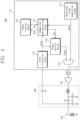
- FIG. 4 is a schematic block diagram of an NFC device 100 according to an embodiment of the inventive concepts. It will be appreciated that the schematic block diagram of FIG. 4 may not illustrate all of the components of the NFC device 100, but instead only illustrates certain of the signal transmission components that may be used in certain embodiments of the inventive concepts.
- the NFC device 100 includes a transmitter 110, a transmission amplifier 120, a matching circuit 130, and an antenna 140.
- the transmitter 110 may operate in a phase measurement mode and a transmission mode.
- the transmitter 110 transmits a transmit clock CLKt to the transmission amplifier 120.
- the transmit clock CLKt may be any appropriate waveform such as, for example, a pulse signal having a certain frequency.
- the transmitter 110 extracts an extraction clock CLKe from a waveform, which is formed in the antenna 140 and the matching circuit 130 in response to the transmit clock CLKt.
- the transmitter 110 may store information regarding a phase difference between the transmit clock CLKt and the extraction clock CLKe.
- the transmitter 110 may adjust a phase of a transmission signal based on the stored information regarding the phase difference.
- the transmitter 110 may include, for example, a reference clock generation block 111, a multiplexer 112, a clock extraction block 113, a comparison and selection block 114, a phase lookup table 115, and a phase control block 116.
- the reference clock generation block 111 may generate a reference clock CLKr.
- the reference clock CLKr may have a center frequency that is determined by the NFC standard.
- the reference clock CLKr may have a center frequency of 13.56 MHz.
- the reference clock CLKr may be, for example, a pulse waveform.
- the reference clock CLKr may be transmitted to the multiplexer 112 and the comparison and selection block 114.
- the multiplexer 112 may receive the reference clock CLKr from the reference clock generation block 111 and may receive an adjusted clock CLKa from the phase control block 116. In the phase measurement mode, the multiplexer 112 may output the reference clock CLKr as the transmit clock CLKt. The transmit clock CLKt may be transmitted to the transmission amplifier 120. In the transmission mode, the multiplexer 112 may output the adjusted clock CLKa. Transmission information IF may be added to the adjusted clock CLKa. The adjusted clock CLKa including the transmission information IF added thereto may be transmitted to the transmission amplifier 120 as an information signal SIGi.
- the clock extraction block 113 may extract the extraction clock CLKe from a waveform formed in the antenna 140 and the matching circuit 130. For example, the clock extraction block 113 may output the extraction clock CLKe that has the same phase as the waveform formed in the antenna 140 and the matching circuit 130. The extraction clock CLKe may be transmitted to the comparison and selection block 114 and the phase control block 116.
- the comparison and selection block 114 may compare the reference clock CLKr and the extraction clock CLKe in the phase measurement mode.
- the comparison and selection block 114 since the multiplexer 112 outputs the reference clock CLKr as the transmit clock CLKt in the phase measurement mode, the comparison and selection block 114 may be regarded as comparing phases of the reference clock CLKr and the extraction clock CLKe in the phase measurement mode.
- the comparison and selection block 114 may detect a phase difference ⁇ between the reference clock CLKr and the extraction clock CLKe based on the result of the comparison.
- the detected phase difference ⁇ may include information about a difference between the center frequency FC of the transmission signal and a resonant frequency of the antenna 140 and the matching circuit 130.
- the communication distance D decreases due to a path delay that is generated when the resonant frequency Fres and the center frequency FC differ from each other.
- the path delay may be quantified as the phase difference ⁇ between the reference clock CLKr and the extraction clock CLKe. That is, a difference between the resonant frequency and the center frequency may be quantified by the magnitude and sign of the phase difference ⁇ .
- the comparison and selection block 114 may obtain phase selection information ⁇ s corresponding to the phase difference ⁇ with reference to the phase lookup table 115.
- the phase selection information ⁇ s includes information about how much the phase of a transmission signal (e.g., a phase of the information signal SIGi) should be adjusted in the transmission mode to compensate for a difference between the resonant frequency and the center frequency.
- the phase lookup table 115 may store a plurality of phase differences ⁇ and corresponding phase selection information ⁇ s for each of the phase differences. This information may be stored, for example, in the form of a table.
- the comparison and selection block 114 may obtain the phase selection information ⁇ s corresponding to the phase difference ⁇ with reference to the phase lookup table 115.
- the phase selection information ⁇ s may be transmitted to the phase control block 116.
- the phase control block 116 may store the phase selection information ⁇ s in the phase measurement mode. In the transmission mode, the phase control block 116 may adjust the extraction clock CLKe (e.g., adjust the phase of the extraction clock CLKe) based on the phase selection information ⁇ s to output the adjusted clock CLKa.
- the extraction clock CLKe e.g., adjust the phase of the extraction clock CLKe
- the transmitter 110 is described as including various blocks.
- the blocks included in the transmitter 110 may be implemented with hardware such as a semiconductor circuit or an integrated circuit, software driven in an integrated circuit, or a combination of hardware and software.
- the transmission amplifier 120 may amplify a signal from the transmitter 110 and may transmit the amplified signal to the matching circuit 130.
- the matching circuit 130 may provide impedance matching with regard to the antenna 140.
- the matching circuit 130 includes an inductor L and first to fourth capacitors C1 to C4. A first end of the inductor L is connected to an output of the transmission amplifier 120, and a second end thereof is connected to first ends of the first and second capacitors C1 and C2. A second end of the first capacitor C1 is connected to a ground electrode to which a ground voltage is supplied. A second end of the second capacitor C2 is connected to first ends of the third and fourth capacitors C3 and C4 and the antenna 140. A second end of the third capacitor C3 is connected to the ground electrode. A second end of the fourth capacitor C4 is connected to the clock extraction block 113 of the transmitter 110.
- FIG. 4 illustrates one example matching circuit 130 and that matching circuits having different configurations may be provided in other embodiments. It will also be appreciated that the above-described connections may be direct or indirect connections.
- FIG. 5 is a graph illustrating an example in which the NFC device 100 of FIG. 4 performs phase measurement and transmission in a card mode.
- the abscissa represents time T
- the ordinate represents a service mode SM, an operating sequence SQ, a transmit signal TXS, and a receive signal RXS of the NFC device 100.
- the service mode SM of the NFC device 100 is changed from an OFF state to an ON state at a point in time T1.
- power may be supplied to the NFC device 100, or the NFC device 100 may be activated.
- the transmitter 110 may enter the phase measurement mode.
- the operating sequence SQ may enter a radiation interval RI at a point in time T2
- the operating sequence SQ may enter a calculation interval CI at a point in time T3.
- the transmitter 110 may output the reference clock CLKr as the transmit clock CLKt.
- the transmit clock CLKt may form a waveform in the antenna 140 and the matching circuit 130, and a wireless signal corresponding to the generated waveform may be radiated from the antenna 140. If the waveform is stabilized during the radiation interval RI, as described with reference to FIG.
- the phase difference ⁇ between the reference clock CLKr and the extracted clock CLKe that is extracted from the generated waveform is determined during the calculation interval CI.
- the transmitter 110 determines and may store the phase selection information ⁇ s in the phase control block 116 in response to the determined phase difference ⁇ .
- the transmitter 110 may enter the transmission mode. Thereafter, a signal radiated from an external reader may be received as the receive signal RXS in the antenna 140 at a point in time T4.
- the receive signal RXS may be a continuous wave.
- the receive signal RXS may be received through a receiver (not illustrated) and may be used to supply power to the NFC device 100.
- the receive signal RXS may include reception information that is received at antenna 140 at a point in time T5.
- the receive signal RXS may be of a form in which the reception information is added to the continuous wave.
- the operating sequence SQ may enter a reception interval RX.
- the receiver may interpret the reception information during the reception interval RX. When the reception interval RX ends, the receive signal RXS may be restored to a continuous wave that does not include the reception information.
- the transmitter 110 may perform transmission at a point in time T6 to send transmission information as a response to the reception information that is received during the reception interval RX.
- the phase control block 116 may adjust the extraction clock CLKe which may be, for example, a clock which is extracted from the continuous wave of the receive signal RXS, based on the phase selection information ⁇ s and may output the adjusted clock CLKa.
- the information signal SIGi which may comprise the adjusted clock CLKa with the transmission information IF added thereto, may be radiated as the transmit signal TXS through the antenna 140.
- FIG. 6 shows an example of waveforms of the reference clock CLKr, the transmit signal TXS, the extraction clock CLKe, and the adjusted clock CLKa when the resonant frequency Fres of the NFC device 100 is a first resonant frequency that coincides with the center frequency FC of the near field communication.
- a phase may not be changed. In this case, a phase of a waveform of the transmit signal TXS coincides with a phase of the reference clock CLKr.
- a phase of the extraction clock CLKe extracted from the transmit signal TXS coincides with a phase of the reference clock CLKr. Accordingly, the phase difference ⁇ is "0", and the phase selection information ⁇ s for compensating for the phase difference ⁇ may indicate "no phase adjustment".
- the adjusted clock CLKa has the same phase as the extraction clock CLKe. That is, in the transmission mode, the phase control block 116 may output the extraction clock CLKe, which is extracted from the continuous wave of the receive signal RXS (refer to FIG. 5 ), as the adjusted clock CLKa without phase adjustment.
- FIG. 7 shows an example of waveforms of the reference clock CLKr, the transmit signal TXS, the extraction clock CLKe, and the adjusted clock CLKa when the resonant frequency Fres of the NFC device 100 is a second resonant frequency Fres1 that is less than the center frequency FC of the near field communication.
- a phase of a waveform of the transmit signal TXS is delayed relative to a phase of the reference clock CLKr.
- a phase of the extraction clock CLKe that is extracted from the transmit signal TXS is delayed relative to a phase of the reference clock CLKr.
- the phase of the waveform of the transmit signal TXS and the phase of the extraction clock CLKe may be delayed by 90 degrees relative to the reference clock CLKr.
- the phase difference ⁇ is "90 degrees (90°)”
- the phase selection information ⁇ s for compensating for the phase difference ⁇ indicates "a 90-degree decrease (or advance)”.
- the adjusted clock CLKa has a phase that is advanced by 90 degrees relative to the extraction clock CLKe. That is, in the transmission mode, the phase control block 116 may output an adjusted clock CLKa that is obtained by advancing a phase of the extraction clock CLKe, which is extracted from the continuous wave of the receive signal RXS (refer to FIG. 5 ), by 90 degrees.
- FIG. 8 shows an example of waveforms of the reference clock CLKr, the transmit signal TXS, the extraction clock CLKe, and the adjusted clock CLKa when the resonant frequency Fres of the NFC device 100 is a third resonant frequency Fres2 that is higher than the center frequency FC of the near field communication.
- the resonant frequency Fres is the third resonant frequency Fres2 that exceeds the center frequency FC
- the phase of the waveform of the transmit signal TXS and the phase of the extraction clock CLKe that is extracted from the transmit signal TXS are advanced relative to a phase of the reference clock CLKr.
- the phase of the waveform of the transmit signal TXS and the phase of the extraction clock CLKe may be advanced by 90 degrees relative to the reference clock CLKr.
- the phase difference ⁇ is "-90 degrees (-90°)”
- the phase selection information ⁇ s for compensating for the phase difference ⁇ may indicate "a -90 degree increase (or delay)”.
- the adjusted clock CLKa has a phase that is delayed by 90 degrees relative to the extraction clock CLKe. That is, in the transmission mode, the phase control block 116 may output an adjusted clock CLKa that is obtained by delaying a phase of the extraction clock CLKe, which is extracted from the continuous wave of the receive signal RXS (refer to FIG. 5 ), by 90 degrees.
- FIG. 9 is a block diagram illustrating an example of the phase control block 116 of the NFC device 100 of FIG. 4 .
- the phase control block 116 includes a phase locked loop 116a, a phase splitter 116b, and a clock selector 116c.
- the phase locked loop 116a may receive the extraction clock CLKe and output a phase locked clock CLKl that has the same frequency as the extraction clock CLKe and the same phase as the extraction clock CLKe when the transmitter 110 operates in the transmission mode. For example, the phase locked loop 116a may output the phase locked clock CLKl that has the same phase as the receive signal RXS or a continuous wave of the receive signal RXS before the transmission sequence TX (refer to FIG. 5 ) starts. If the phase locked clock CLK1 is output, the phase locked loop 116a may maintain a phase of the phase locked clock CLK1 even though a phase of the extraction clock CLKe changes. That is, even though a phase of the extraction clock CLKe changes due to mixing the transmit signal TXS and the receive signal RXS in the transmission sequence TX, the phase locked loop 116a may maintain the phase locked clock CLKl.
- the phase splitter 116b may receive the phase locked clock CLK1 and may output a plurality of clocks CLK1 to CLKn that have the same frequency as the phase locked clock CLK1 and have different phases.
- the phase splitter 116b may include a plurality of delays D1 to Dn that are serially connected to each other. A time delay of each delay D1 to Dn may be smaller than a quarter of a period of the phase locked clock CLKl.
- the phase locked clock CLK1 may be input to the first delay D1.
- the phase splitter 116b may output the plurality of clocks CLK1 to CLKn.
- the clock selector 116c may select one of the plurality of clocks CLK1 to CLKn as the adjusted clock CLKa based on the phase selection information ⁇ s.
- the phase locked loop 116a may be omitted from the phase control block 116. If the phase locked loop 116a is omitted, the phase splitter 116b may generate the plurality of clocks CLK1 to CLKn using the extraction clock CLKe.
- a waveform formed in the antenna 140 and the matching circuit 130 corresponds to a mixed shape of the transmit signal TXS and the receive signal RXS, and the transmit signal TXS may be dominant. Accordingly, the extraction clock CLKe may follow the transmit signal TXS. Clock adjustment by the clock selector 116c may be accumulated every clock cycle due to iteration of the process in which the transmit signal TXS is extracted as the extraction clock CLKe, the extraction clock CLKe is output as the adjusted clock CLKa after being adjusted by the clock selector 116c, and the adjusted clock CLKa is sent as the transmit signal TXS.
- the clock selector 116c may dynamically select the plurality of clocks CLK1 to CLKn. For example, the clock selector 116c may select a clock, which is designated by the phase selection information ⁇ s, of the clocks CLK1 to CLKn as a start clock, and then, may select the same or a different clock every clock cycle. For example, the clock selector 116c may select an output of the latter delay or an output of the former delay every clock cycle.
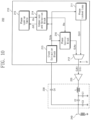
- FIG. 10 is a schematic block diagram that illustrates an NFC device 200 according to further embodiments of the inventive concepts.
- the NFC device 200 includes a transmitter 210, a transmission amplifier 220, a matching circuit 230, and an antenna 240.
- the transmission amplifier 220, the matching circuit 230, and the antenna 240 may be the same as the transmission amplifier 120, the matching circuit 130, and the antenna 140 of FIG. 4 . A detailed description thereof is thus omitted.
- the transmitter 210 includes a phase locked loop 211, a multiplexer 212, a clock extraction block 213, a comparison and selection block 214, a phase lookup table 215, and a phase control block 216.
- the phase locked loop 211 may output a phase locked clock CLKl that has the same frequency as the extraction clock CLKe and the same phase as the extraction clock CLKe.
- the multiplexer 212 may output the phase locked clock CLK1 to the transmission amplifier 220 as the transmit clock CLKt in the phase measurement mode.
- the multiplexer 212 may output the adjusted clock CLKa in the transmission mode.
- the information signal SIGi in which the transmission information IF is added to the adjusted clock CLKa may be transmitted to the transmission amplifier 220.
- the clock extraction block 213, the comparison and selection block 214, the phase lookup table 215, and the phase control block 216 may operate the same as the clock extraction block 113, the comparison and selection block 114, the phase lookup table 115, and the phase control block 116 of FIG. 4 , respectively, except that the clock extraction block 213 transmits the extraction clock CLKe to the phase locked loop 211. A detailed description of these elements is thus omitted.
- FIG. 11 is a graph illustrating an example in which the NFC device 200 of FIG. 10 performs phase measurement and adjustment and transmission in a card mode.
- the abscissa represents the time T
- the ordinate represents a service mode SM, an operating sequence SQ, a transmit signal TXS, and a receive signal RXS of the NFC device 200.
- the service mode SM of the NFC device 200 is changed from an OFF state to an ON state at a point in time T1.
- power may be supplied to the NFC device 200, or the NFC device 200 may be activated.
- a signal radiated from an external reader may be received as the receive signal RXS in the antenna 240 at a point in time T2.
- the receive signal RXS may be a continuous wave.
- the receive signal RXS may be received through a receiver (not illustrated) and may be used to supply power to the NFC device 200.
- the transmitter 210 may enter the phase measurement mode.
- the operating sequence SQ may enter a radiation interval RI at a point in time T3
- the operating sequence SQ may enter a calculation interval CI at a point in time T4.
- the phase locked loop 211 of the transmitter 210 may output the phase locked clock CLK1 that has the same phase as the receive signal RXS or a continuous wave of the receive signal RXS.
- the transmitter 210 outputs the phase locked clock CLKl as the transmit clock CLKt to the transmission amplifier 220.
- the transmit clock CLKt may form a waveform in the antenna 240 and the matching circuit 230, and a wireless signal corresponding to the generated waveform may be radiated from the antenna 240. If the waveform is stabilized during the radiation interval RI, as described with reference to FIGS. 4 and 10 , the phase difference ⁇ is determined during the calculation interval CI.
- the transmitter 210 determines and may store the phase selection information ⁇ s in the phase control block 216 in response to the determined phase difference ⁇ .
- the receive signal RXS may include reception information (e.g., data, commands, etc.) that is received at antenna 240 at a point in time T5.
- the receive signal RXS may comprise a continuous wave that has reception information added thereto.
- the operating sequence SQ may enter a reception interval RX.
- the receiver may interpret the reception information during the reception interval RX.
- the receive signal RXS may be a continuous wave that does not include reception information.
- the transmitter 210 may perform transmission at a point in time T6 to send transmission information (e.g., data, commands, etc.) as a response to the reception information that is received during the reception interval RX.
- the phase control block 216 may adjust the extraction clock CLKe which may be, for example, a clock which is extracted from the continuous wave of the receive signal RXS, based on the phase selection information ⁇ s, and may output the adjusted clock CLKa.
- the information signal SIGi which may comprise the adjusted clock CLKa with the transmission information IF added thereto, may be radiated as the transmit signal TXS through the antenna 240.
- the NFC device 100 described with reference to FIGS. 4 and 5 may automatically detect the phase selection information ⁇ s using the reference clock generation block 111 before near field communication starts; on the other hand, the NFC device 200 described with reference to FIGS. 10 and 11 may detect the phase selection information ⁇ s using the receive signal RXS after near field communication starts.
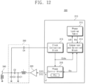
- FIG. 12 is a schematic block diagram that illustrates an NFC device 300 according to still further embodiments of the inventive concepts.
- the NFC device 300 includes a transmitter 310, a transmission amplifier 320, a matching circuit 330, and an antenna 340.
- the transmission amplifier 320, the matching circuit 330, and the antenna 340 may be the same as the transmission amplifier 120, the matching circuit 130, and the antenna 140 of the NFC device 100 of FIG. 4 . Accordingly, detailed description thereof is omitted.
- the transmitter 310 includes a clock extraction block 313, a comparison and selection block 314, a phase lookup table 315, and a phase control block 316.
- the phase control block 316 may include a phase locked loop PLL.
- the phase locked loop PLL may output the phase locked clock CLK1, which has the same frequency as the extraction clock CLKe and the same phase as the extraction clock CLKe, to the transmission amplifier 320 as the transmit clock CLKt in the phase measurement mode.
- the phase locked loop PLL may adjust a phase of the phase locked clock CLK1 based on the phase selection information ⁇ s and may output the adjusted clock CLKa.
- the information signal SIGi which comprises the adjusted clock CLKa with the transmission information IF added thereto, is transmitted to the transmission amplifier 320 in the transmission mode.
- the clock extraction block 313, the comparison and selection block 314, the phase lookup table 315, and the phase control block 316 may operate the same as the clock extraction block 113, the comparison and selection block 114, the phase lookup table 115, and the phase control block 116 of FIG. 4 . Accordingly, detailed description thereof is omitted.
- the transmitter 210 of FIG. 10 includes the phase locked loop 211 that generates the phase locked clock CLK1 in the phase measurement mode. Accordingly, as described with reference to FIG. 9 , the phase control block 216 may include the phase locked loop 116a or may not include the phase locked loop 116a. In contrast, the transmitter 310 of FIG. 12 may use the phase locked loop PLL of the phase control block 316 in both the phase measurement mode and the transmission mode.
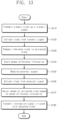
- FIG. 13 is a flowchart illustrating method of operating an NFC device according to an embodiment of the inventive concepts.
- the transmitter 110, 210, or 310 of the NFC device 100, 200, or 300 may send a basic clock as the transmit clock CLKt to the transmit amplifier 120, 130, 140.
- the basic clock may be the reference clock CLKr that is generated by the reference clock generation block 111 or the phase locked clock CLKl that is generated by the phase locked loop 211 or PLL.
- the transmit clock CLKt is transmitted by the NFC device as a transmit signal TXS.
- the transmitter 110, 210, or 310 may extract, for example, the extraction clock CLKe from the transmit signal TXS.
- the transmitter 110, 210, or 310 may compare the reference clock CLKr or CLKl to the extraction clock CLKe.
- the transmitter 110, 210, or 310 may store phase difference information between the reference clock CLKr or CLK1 and the extraction clock CLKe, for example, the phase selection information ⁇ s or the phase difference ⁇ .
- the transmitter 110, 210, or 310 may receive an external signal.
- the transmitter 110, 210, or 310 may receive a continuous wave from an external NFC device.
- the transmitter 110, 210, or 310 may extract a clock from the received external signal.
- the transmitter 110, 210, or 310 may adjust a phase of the extracted clock CLKe based on the phase difference information to provide an adjusted clock CLKa.
- the transmitter 110, 210, or 310 may transmit an information signal in synchronization with the adjusted clock CLKa.
- FIG. 14 is a block diagram illustrating a mobile device 1000, according to an embodiment of the inventive concepts.
- the mobile device 1000 includes an application processor 1010, a codec 1020, a speaker 1030, a microphone 1040, a display device 1050, a camera 1060, a modem 1070, a storage device 1080, a random access memory 1090, a NFC device 1100 and a user input interface 1110.
- the application processor 1010 may drive an operating system that operates the mobile device 1000 and may drive various applications on the operating system.
- the codec 1020 may perform coding and decoding of signals such as, for example, an image signal.
- the codec 1020 may perform a task associated with processing a voice signal or an image signal under delegation of the application processor 1010.
- the speaker 1030 may play a voice signal from the codec 1020.
- the microphone 1040 may detect sound sensed from the outside, may convert the detected sound into a voice signal, and may output the voice signal to the codec 1020.
- the display device 1050 may play an image signal from the codec 1020.
- the camera 1060 may convert a scene in a range of vision into an electrical image signal and may output the image signal to the codec 1020.
- the modem 1070 may perform wireless or wired communication with an external device. In response to a request of the application processor 1010, the modem 1070 may transmit data to an external device or may request data from the external device.
- the storage device 1080 may be main storage of the mobile device 1000. The storage device 1080 may be used to store data for a long time and may retain data stored therein even at power-off.
- the random access memory 1090 may be a main memory of the mobile device 1000. The random access memory 1090 may be used for the master devices, such as the application processor 1010, the modem 1070, and the codec 1020, to temporarily store data.
- the NFC device 1100 may be the NFC device 100, 200, or 300 described with reference to FIGS. 1 to 13 .
- the NFC device 1100 may operate as a reader or a card.
- the NFC device 1100 may detect a phase difference and may adjust a phase of a transmit clock based on the detected phase difference. Accordingly, accuracy of the NFC device 1100 may be improved, and the reliability of the mobile device 1000 may be improved.
- the user input interface 1110 may include various devices for receiving an input from a user.
- the user input interface 1110 may include devices, which directly receive an input from the user, such as touch panels, touch screens, buttons, and keyboards, or devices, which indirectly receive results generated by actions of the user, such as an optical sensor, a proximity sensor, a gyroscope sensor, and a pressure sensor.
- a communication distance may be substantially maintained even though a center frequency of the signal transmission and a resonant frequency of a near field communication device differ from each other. Accordingly, near field communication devices may be provided that may exhibit improved communication quality.
Landscapes
- Engineering & Computer Science (AREA)
- Computer Networks & Wireless Communication (AREA)
- Signal Processing (AREA)
- Health & Medical Sciences (AREA)
- Toxicology (AREA)
- Physics & Mathematics (AREA)
- Electromagnetism (AREA)
- General Health & Medical Sciences (AREA)
- Artificial Intelligence (AREA)
- Computer Vision & Pattern Recognition (AREA)
- General Physics & Mathematics (AREA)
- Theoretical Computer Science (AREA)
- Near-Field Transmission Systems (AREA)
- Power Engineering (AREA)
- Transmitters (AREA)
Claims (14)
- Nahfeldkommunikationsgerät, das Folgendes umfasst:eine Antenne (140);einen Sendeverstärker (120);eine Anpassungsschaltung (130), die zwischen der Antenne (140) und dem Sendeverstärker (120) angeschlossen ist; undeinen Sender (110),wobei der Sender (110) einen Referenztakterzeugungsblock (111) umfasst, der so konfiguriert ist, dass er einen Referenztakt (CLKr) ausgibt,wobei der Sender (110) in einem Phasenmessmodus so konfiguriert ist, dass er den Referenztakt (CLKr) als einen Sendetakt (CLKt) ausgibt, um den Sendetakt (CLKt) über den Sendeverstärker (120) an die Anpassungsschaltung (130) zu übertragen, um in der Anpassungsschaltung (130) und der Antenne (140) eine Wellenform zu bilden, so dass ein der Wellenform entsprechendes Funksignal von der Antenne (140) abgestrahlt wird, um einen Extraktionstakt (CLKe) zu extrahieren und um Informationen bezüglich einer Phasendifferenz zwischen dem Sendetakt (CLKt) und dem Extraktionstakt (CLKe) zu bestimmen, undwobei der Sender (110) ferner so konfiguriert ist, dass er die Übertragung eines Informationssignals (SIGi) durch die Antenne (140), den Sendeverstärker (120) und die Anpassungsschaltung (130) auf der Grundlage der ermittelten Informationen bezüglich der Phasendifferenz steuert, unddadurch gekennzeichnet, dass der Extraktionstakt (CLKe) aus der in der Anpassungsschaltung (130) gebildeten Wellenform extrahiert wird.
- Nahfeld-Kommunikationsgerät nach Anspruch 1, wobei der Sender (110) umfasst:
einen Vergleichs- und Auswahlblock (114), der so konfiguriert ist, dass er eine Phase des Extraktionstakts (CLKe) mit einer Phase des Sendetakts (CLKt) vergleicht und Phasenauswahlinformationen (θs) entsprechend der Phasendifferenz auf der Grundlage eines Ergebnisses des Vergleichs erzeugt. - Nahfeldkommunikationsgerät nach Anspruch 2, wobei der Sender (110) ferner umfasst:eine Phasennachschlagetabelle (115), die so konfiguriert ist, dass sie Phasendifferenzen und Teile von Phasenauswahlinformationen (θs) speichert, die den jeweiligen Phasendifferenzen entsprechen, undwobei der Vergleichs- und Auswahlblock (114) die ermittelten Informationen bezüglich der Phasendifferenz und die Nachschlagetabelle verwendet, um die Phasenauswahlinformationen (θs) zu erzeugen.
- Nahfeldkommunikationsgerät nach Anspruch 1,
wobei der Sender (110) ferner Folgendes umfasst:
einen Phasensteuerblock (116), der so konfiguriert ist, dass er Informationen bezüglich der Phasendifferenz im Phasenmessmodus speichert. - Nahfeldkommunikationsgerät nach Anspruch 4, wobei die gespeicherten Informationen die Phasenauswahlinformationen (θs) umfassen.
- Nahfeld-Kommunikationsgerät nach Anspruch 4, wobei der Phasensteuerblock (116) in einem Sendemodus einen angepassten Takt (CLKa) ausgibt, indem er eine Phase des Extraktionstakts (CLKe) zumindest teilweise auf der Grundlage der Informationen bezüglich der Phasendifferenz anpasst.
- Nahfeld-Kommunikationsgerät nach Anspruch 6, wobei der Sender (110) ferner Folgendes umfasst:
einen Multiplexer (112), der so konfiguriert ist, dass er den Referenztakt (CLKr) als den Sendetakt (CLKt) im Phasenmessmodus auswählt, um an den Sendeverstärker (120) übertragen zu werden, und den angepassten Takt (CLKa) als den Sendetakt (CLKt) im Sendemodus auswählt, um an den Sendeverstärker (120) übertragen zu werden. - Nahfeldkommunikationsgerät nach Anspruch 7, wobei Übertragungsinformationen (IF) dem angepassten Takt (CLKa) vor der Übertragung des angepassten Takts (CLKa) durch den Sendeverstärker (120) hinzugefügt werden.
- Nahfeld-Kommunikationsvorrichtung nach Anspruch 6, wobei der Phasensteuerblock (116) aufweist:einen Phasenregelkreis (116a), der konfiguriert ist, um einen phasenstarren Takt (CLKI) auszugeben, der auf die Phase des Extraktionstakts (CLKe) verriegelt ist;einen Phasenteiler (116b), der so konfiguriert ist, dass er mehrere Takte (CLK1 bis CLKn) mit unterschiedlichen Phasen durch Einstellen der Phase des phasenverriegelten Takts (CLKI) erzeugt; undeinen Taktwähler (116c), der so konfiguriert ist, dass er einen der mehreren Takte (CLK1 bis CLKn) als den eingestellten Takt (CLKa) auf der Grundlage der gespeicherten Informationen bezüglich der Phasendifferenz auswählt.
- Nahfeldkommunikationsgerät nach Anspruch 6, wobei der Phasensteuerblock (116) Folgendes umfasst:einen Phasenteiler (116b), der so konfiguriert ist, dass er mehrere Takte (CLK1 bis CLKn) mit unterschiedlichen Phasen erzeugt; undeinen Taktwähler (116c), der so konfiguriert ist, dass er einen der mehreren Takte (CLK1 bis CLKn) als den angepassten Takt (CLKa) auf der Grundlage der gespeicherten Informationen bezüglich der Phasendifferenz auswählt,wobei der eine der mehreren Takte (CLK1 bis CLKn), der durch den Taktwähler (116c) unter Verwendung der Informationen bezüglich der Phasendifferenz ausgewählt wird, sich ändert, wenn ein Zyklus des Extraktionstakts (CLKe) im Laufe der Zeit fortschreitet.
- Nahfeldkommunikationsgerät nach Anspruch 1, wobei die Phasendifferenz Informationen über eine Differenz zwischen einer Mittenfrequenz (FC) des Sendetakts (CLKt) und einer Resonanzfrequenz der Antenne (140) und der Anpassungsschaltung (130) anzeigt.
- Nahfeldkommunikationsgerät nach Anspruch 11, wobei der Sender (110) einen zweiten Extraktionstakt (CLKe) aus einer Wellenform eines Signals extrahiert, das über die Antenne (140) von außen empfangen wird, einen angepassten Takt (CLKa) durch Anpassen einer Phase des zweiten Extraktionstakts (CLKe) auf der Grundlage der erfassten Differenz und Senden eines Informationssignals (SIGi) durch den Sendeverstärker (120), die Anpassungsschaltung (130) und die Antenne (140) unter Verwendung des angepassten Takts (CLKa).
- Nahfeldkommunikationsgerät nach Anspruch 6, wobei
der Sender (110) in einem Phasenmessmodus oder einem Sendemodus arbeitet und umfasst:
einen Multiplexer (112), der so konfiguriert ist, dass er den Referenztakt (CLKt) als den Sendetakt (CLKt) im Phasenmessmodus auswählt, um an den Sendeverstärker (120) übertragen zu werden, und den angepassten Takt (CLKa) als den Sendetakt (CLKt) im Sendemodus auswählt, um an den Sendeverstärker (120) übertragen zu werden. - Nahfeld-Kommunikationsgerät nach Anspruch 13, wobei der Sender (110) ferner einen Phasensteuerblock (116) umfasst und wobei der Phasensteuerblock (116) im Sendemodus so konfiguriert ist, dass er einen angepassten Takt (CLKa) durch Anpassen einer Phase des Extraktionstakts (CLKe) ausgibt.
Applications Claiming Priority (2)
| Application Number | Priority Date | Filing Date | Title |
|---|---|---|---|
| KR20160115860 | 2016-09-08 | ||
| KR1020160134493A KR102483557B1 (ko) | 2016-09-08 | 2016-10-17 | 근거리 무선 통신 장치 |
Publications (3)
| Publication Number | Publication Date |
|---|---|
| EP3293666A2 EP3293666A2 (de) | 2018-03-14 |
| EP3293666A3 EP3293666A3 (de) | 2018-04-18 |
| EP3293666B1 true EP3293666B1 (de) | 2025-01-08 |
Family
ID=59558223
Family Applications (1)
| Application Number | Title | Priority Date | Filing Date |
|---|---|---|---|
| EP17184611.6A Active EP3293666B1 (de) | 2016-09-08 | 2017-08-03 | Nahfeldkommunikationsvorrichtung |
Country Status (3)
| Country | Link |
|---|---|
| US (1) | US10334421B2 (de) |
| EP (1) | EP3293666B1 (de) |
| CN (1) | CN107809263B (de) |
Families Citing this family (7)
| Publication number | Priority date | Publication date | Assignee | Title |
|---|---|---|---|---|
| US10756881B2 (en) | 2016-08-01 | 2020-08-25 | Nxp B.V. | Method and system for operating a communications device that communicates via inductive coupling |
| US10567092B2 (en) * | 2017-09-01 | 2020-02-18 | Nxp B.V. | System to calibrate phase using system information |
| FR3080476A1 (fr) * | 2018-04-24 | 2019-10-25 | Stmicroelectronics (Rousset) Sas | Procede de reglage de la phase du signal emis par un objet capable de communiquer sans contact avec un lecteur par modulation active de charge, et objet correspondant |
| FR3095912B1 (fr) * | 2019-05-06 | 2022-05-13 | St Microelectronics Rousset | Procédé de compensation d’un déphasage entre le signal émis par un objet et celui reçu d’un lecteur équipé d’un détecteur d’enveloppe et objet correspondant |
| CN111711472A (zh) * | 2020-06-28 | 2020-09-25 | Oppo广东移动通信有限公司 | Nfc装置输出信号控制方法及终端设备、介质和电子设备 |
| CN112543446B (zh) * | 2020-12-02 | 2023-04-25 | 歌尔科技有限公司 | 基于近场通信的交互方法、可穿戴设备及存储介质 |
| EP4106211A1 (de) * | 2021-06-15 | 2022-12-21 | Nxp B.V. | Rfid-sendeempfänger mit implementierter phasenkalibrierung und phasenkalibrierungsverfahren |
Family Cites Families (13)
| Publication number | Priority date | Publication date | Assignee | Title |
|---|---|---|---|---|
| JPH10187916A (ja) | 1996-12-27 | 1998-07-21 | Rohm Co Ltd | 非接触icカード通信システムにおける応答器 |
| JP2001291081A (ja) | 2000-04-10 | 2001-10-19 | Dainippon Printing Co Ltd | 非接触式情報記憶媒体、その発行装置、外部通信装置及び非接触式情報記憶媒体の通信方法 |
| JP2009130389A (ja) * | 2007-11-19 | 2009-06-11 | Felica Networks Inc | 通信装置、同調周波数調整方法、およびプログラム |
| JP2009302953A (ja) | 2008-06-13 | 2009-12-24 | Toshiba Corp | 非接触データ通信装置 |
| US9473209B2 (en) * | 2008-08-20 | 2016-10-18 | Intel Corporation | Wireless power transfer apparatus and method thereof |
| JP4992125B2 (ja) | 2009-03-31 | 2012-08-08 | 日本電気株式会社 | 携帯端末装置及び該携帯端末装置に用いられるアンテナ共振周波数調整方法 |
| GB2496387B (en) | 2011-11-08 | 2014-02-26 | Cambridge Silicon Radio Ltd | A near field communications reader |
| US8886145B2 (en) * | 2012-03-26 | 2014-11-11 | Sony Corporation | Antenna adjustment circuit, antenna adjustment method, and communication unit |
| US8934836B2 (en) * | 2012-06-28 | 2015-01-13 | Broadcom Corporation | NFC device with PLL controlled active load modulation |
| US8933733B2 (en) * | 2013-01-07 | 2015-01-13 | Mediatek Singapore Pte. Ltd. | Method and system for fast synchronized dynamic switching of a reconfigurable phase locked loop (PLL) for near field communications (NFC) peer to peer (P2P) active communications |
| KR20160039604A (ko) | 2013-06-13 | 2016-04-11 | 쿼드락 가부시키가이샤 | 비접촉 통신 장치 |
| US9590701B2 (en) | 2014-09-08 | 2017-03-07 | Broadcom Corporation | Feedback-based adaptive load modulation (ALM) for a near field communication (NFC) device |
| KR102283255B1 (ko) * | 2014-10-10 | 2021-07-28 | 삼성전자주식회사 | 반도체 장치 |
-
2017
- 2017-02-28 CN CN201710110863.8A patent/CN107809263B/zh active Active
- 2017-03-14 US US15/458,051 patent/US10334421B2/en active Active
- 2017-08-03 EP EP17184611.6A patent/EP3293666B1/de active Active
Also Published As
| Publication number | Publication date |
|---|---|
| EP3293666A2 (de) | 2018-03-14 |
| US10334421B2 (en) | 2019-06-25 |
| CN107809263B (zh) | 2021-04-27 |
| CN107809263A (zh) | 2018-03-16 |
| US20180070198A1 (en) | 2018-03-08 |
| EP3293666A3 (de) | 2018-04-18 |
Similar Documents
| Publication | Publication Date | Title |
|---|---|---|
| EP3293666B1 (de) | Nahfeldkommunikationsvorrichtung | |
| US8922525B2 (en) | Touch-controlled electronic device and method for reducing wireless signal interference to touch sensing function | |
| CN109756249B (zh) | 近场通信设备 | |
| US10756881B2 (en) | Method and system for operating a communications device that communicates via inductive coupling | |
| US10567092B2 (en) | System to calibrate phase using system information | |
| CN107682292B (zh) | Nfc系统中有源负载调制的相位的高分辨率调谐方法和系统 | |
| EP3461018B1 (de) | Verfahren und system zum betrieb einer kommunikationsvorrichtung mittels induktiver kopplung | |
| KR102283255B1 (ko) | 반도체 장치 | |
| US9912567B2 (en) | Method of handling NFC device with non-fixed low power polling number and NFC device using the same | |
| KR20160031234A (ko) | 무선 주파수 처리 장치 및 방법 | |
| CN103366213A (zh) | 主动式电子标签及其信号调变方法 | |
| CN108462511B (zh) | 近场通信设备及近场通信设备的操作方法 | |
| US11196158B2 (en) | Electric composite detection antenna | |
| US8923383B2 (en) | Transmitter and transmitting method using delay locked loop | |
| CN107852189B (zh) | 通信装置、通信方法和通信系统 | |
| CN103870864A (zh) | 用于记忆卡主动式电子卷标装置 | |
| KR102483557B1 (ko) | 근거리 무선 통신 장치 | |
| CN105519000B (zh) | 无线通信装置和移动设备 | |
| US9838061B1 (en) | Portable electronic communications device with human tissue contact detection | |
| KR102251880B1 (ko) | 근거리 무선 통신 장치 및 근거리 무선 통신 장치의 동작 방법 | |
| KR20140112319A (ko) | 자동 정합 회로를 근거로 한 rfid 리더 및 그의 제어 방법 | |
| US20240106497A1 (en) | Near-field communication chip, phase synchronization method, and electronic device | |
| CN105490704B (zh) | 一种信息处理方法及电子设备 | |
| JP2016178481A (ja) | 通信モジュール及び通信制御方法 | |
| US10135497B2 (en) | Near field communication device |
Legal Events
| Date | Code | Title | Description |
|---|---|---|---|
| PUAI | Public reference made under article 153(3) epc to a published international application that has entered the european phase |
Free format text: ORIGINAL CODE: 0009012 |
|
| STAA | Information on the status of an ep patent application or granted ep patent |
Free format text: STATUS: THE APPLICATION HAS BEEN PUBLISHED |
|
| AK | Designated contracting states |
Kind code of ref document: A2 Designated state(s): AL AT BE BG CH CY CZ DE DK EE ES FI FR GB GR HR HU IE IS IT LI LT LU LV MC MK MT NL NO PL PT RO RS SE SI SK SM TR |
|
| AX | Request for extension of the european patent |
Extension state: BA ME |
|
| PUAL | Search report despatched |
Free format text: ORIGINAL CODE: 0009013 |
|
| AK | Designated contracting states |
Kind code of ref document: A3 Designated state(s): AL AT BE BG CH CY CZ DE DK EE ES FI FR GB GR HR HU IE IS IT LI LT LU LV MC MK MT NL NO PL PT RO RS SE SI SK SM TR |
|
| AX | Request for extension of the european patent |
Extension state: BA ME |
|
| RIC1 | Information provided on ipc code assigned before grant |
Ipc: H04B 5/00 20060101ALI20180315BHEP Ipc: G06K 7/10 20060101AFI20180315BHEP Ipc: H04B 5/02 20060101ALI20180315BHEP |
|
| STAA | Information on the status of an ep patent application or granted ep patent |
Free format text: STATUS: REQUEST FOR EXAMINATION WAS MADE |
|
| 17P | Request for examination filed |
Effective date: 20181012 |
|
| RBV | Designated contracting states (corrected) |
Designated state(s): AL AT BE BG CH CY CZ DE DK EE ES FI FR GB GR HR HU IE IS IT LI LT LU LV MC MK MT NL NO PL PT RO RS SE SI SK SM TR |
|
| STAA | Information on the status of an ep patent application or granted ep patent |
Free format text: STATUS: EXAMINATION IS IN PROGRESS |
|
| 17Q | First examination report despatched |
Effective date: 20190325 |
|
| P01 | Opt-out of the competence of the unified patent court (upc) registered |
Effective date: 20230520 |
|
| REG | Reference to a national code |
Ref country code: DE Ref legal event code: R079 Free format text: PREVIOUS MAIN CLASS: G06K0007100000 Ipc: H04B0005240000 Ref country code: DE Ref legal event code: R079 Ref document number: 602017087212 Country of ref document: DE Free format text: PREVIOUS MAIN CLASS: G06K0007100000 Ipc: H04B0005240000 |
|
| GRAP | Despatch of communication of intention to grant a patent |
Free format text: ORIGINAL CODE: EPIDOSNIGR1 |
|
| STAA | Information on the status of an ep patent application or granted ep patent |
Free format text: STATUS: GRANT OF PATENT IS INTENDED |
|
| GRAS | Grant fee paid |
Free format text: ORIGINAL CODE: EPIDOSNIGR3 |
|
| GRAA | (expected) grant |
Free format text: ORIGINAL CODE: 0009210 |
|
| STAA | Information on the status of an ep patent application or granted ep patent |
Free format text: STATUS: THE PATENT HAS BEEN GRANTED |
|
| RIC1 | Information provided on ipc code assigned before grant |
Ipc: H04W 4/80 20180101ALI20241101BHEP Ipc: H04B 5/48 20240101ALI20241101BHEP Ipc: H04B 5/24 20240101AFI20241101BHEP |
|
| INTG | Intention to grant announced |
Effective date: 20241114 |
|
| AK | Designated contracting states |
Kind code of ref document: B1 Designated state(s): AL AT BE BG CH CY CZ DE DK EE ES FI FR GB GR HR HU IE IS IT LI LT LU LV MC MK MT NL NO PL PT RO RS SE SI SK SM TR |
|
| REG | Reference to a national code |
Ref country code: GB Ref legal event code: FG4D |
|
| REG | Reference to a national code |
Ref country code: CH Ref legal event code: EP |
|
| REG | Reference to a national code |
Ref country code: DE Ref legal event code: R096 Ref document number: 602017087212 Country of ref document: DE |
|
| REG | Reference to a national code |
Ref country code: IE Ref legal event code: FG4D |
|
| REG | Reference to a national code |
Ref country code: NL Ref legal event code: FP |
|
| REG | Reference to a national code |
Ref country code: LT Ref legal event code: MG9D |
|
| REG | Reference to a national code |
Ref country code: AT Ref legal event code: MK05 Ref document number: 1758998 Country of ref document: AT Kind code of ref document: T Effective date: 20250108 |
|
| PG25 | Lapsed in a contracting state [announced via postgrant information from national office to epo] |
Ref country code: RS Free format text: LAPSE BECAUSE OF FAILURE TO SUBMIT A TRANSLATION OF THE DESCRIPTION OR TO PAY THE FEE WITHIN THE PRESCRIBED TIME-LIMIT Effective date: 20250408 |
|
| PG25 | Lapsed in a contracting state [announced via postgrant information from national office to epo] |
Ref country code: FI Free format text: LAPSE BECAUSE OF FAILURE TO SUBMIT A TRANSLATION OF THE DESCRIPTION OR TO PAY THE FEE WITHIN THE PRESCRIBED TIME-LIMIT Effective date: 20250108 |
|
| PG25 | Lapsed in a contracting state [announced via postgrant information from national office to epo] |
Ref country code: PL Free format text: LAPSE BECAUSE OF FAILURE TO SUBMIT A TRANSLATION OF THE DESCRIPTION OR TO PAY THE FEE WITHIN THE PRESCRIBED TIME-LIMIT Effective date: 20250108 |
|
| PG25 | Lapsed in a contracting state [announced via postgrant information from national office to epo] |
Ref country code: ES Free format text: LAPSE BECAUSE OF FAILURE TO SUBMIT A TRANSLATION OF THE DESCRIPTION OR TO PAY THE FEE WITHIN THE PRESCRIBED TIME-LIMIT Effective date: 20250108 |
|
| PGFP | Annual fee paid to national office [announced via postgrant information from national office to epo] |
Ref country code: GB Payment date: 20250626 Year of fee payment: 9 |
|
| PG25 | Lapsed in a contracting state [announced via postgrant information from national office to epo] |
Ref country code: NO Free format text: LAPSE BECAUSE OF FAILURE TO SUBMIT A TRANSLATION OF THE DESCRIPTION OR TO PAY THE FEE WITHIN THE PRESCRIBED TIME-LIMIT Effective date: 20250408 Ref country code: IS Free format text: LAPSE BECAUSE OF FAILURE TO SUBMIT A TRANSLATION OF THE DESCRIPTION OR TO PAY THE FEE WITHIN THE PRESCRIBED TIME-LIMIT Effective date: 20250508 |
|
| PGFP | Annual fee paid to national office [announced via postgrant information from national office to epo] |
Ref country code: NL Payment date: 20250627 Year of fee payment: 9 |
|
| PG25 | Lapsed in a contracting state [announced via postgrant information from national office to epo] |
Ref country code: HR Free format text: LAPSE BECAUSE OF FAILURE TO SUBMIT A TRANSLATION OF THE DESCRIPTION OR TO PAY THE FEE WITHIN THE PRESCRIBED TIME-LIMIT Effective date: 20250108 |
|
| PG25 | Lapsed in a contracting state [announced via postgrant information from national office to epo] |
Ref country code: LV Free format text: LAPSE BECAUSE OF FAILURE TO SUBMIT A TRANSLATION OF THE DESCRIPTION OR TO PAY THE FEE WITHIN THE PRESCRIBED TIME-LIMIT Effective date: 20250108 Ref country code: PT Free format text: LAPSE BECAUSE OF FAILURE TO SUBMIT A TRANSLATION OF THE DESCRIPTION OR TO PAY THE FEE WITHIN THE PRESCRIBED TIME-LIMIT Effective date: 20250508 |
|
| PG25 | Lapsed in a contracting state [announced via postgrant information from national office to epo] |
Ref country code: BG Free format text: LAPSE BECAUSE OF FAILURE TO SUBMIT A TRANSLATION OF THE DESCRIPTION OR TO PAY THE FEE WITHIN THE PRESCRIBED TIME-LIMIT Effective date: 20250108 Ref country code: GR Free format text: LAPSE BECAUSE OF FAILURE TO SUBMIT A TRANSLATION OF THE DESCRIPTION OR TO PAY THE FEE WITHIN THE PRESCRIBED TIME-LIMIT Effective date: 20250409 |
|
| PG25 | Lapsed in a contracting state [announced via postgrant information from national office to epo] |
Ref country code: AT Free format text: LAPSE BECAUSE OF FAILURE TO SUBMIT A TRANSLATION OF THE DESCRIPTION OR TO PAY THE FEE WITHIN THE PRESCRIBED TIME-LIMIT Effective date: 20250108 |
|
| PG25 | Lapsed in a contracting state [announced via postgrant information from national office to epo] |
Ref country code: SE Free format text: LAPSE BECAUSE OF FAILURE TO SUBMIT A TRANSLATION OF THE DESCRIPTION OR TO PAY THE FEE WITHIN THE PRESCRIBED TIME-LIMIT Effective date: 20250108 |
|
| PG25 | Lapsed in a contracting state [announced via postgrant information from national office to epo] |
Ref country code: SM Free format text: LAPSE BECAUSE OF FAILURE TO SUBMIT A TRANSLATION OF THE DESCRIPTION OR TO PAY THE FEE WITHIN THE PRESCRIBED TIME-LIMIT Effective date: 20250108 |
|
| REG | Reference to a national code |
Ref country code: DE Ref legal event code: R097 Ref document number: 602017087212 Country of ref document: DE |
|
| PG25 | Lapsed in a contracting state [announced via postgrant information from national office to epo] |
Ref country code: DK Free format text: LAPSE BECAUSE OF FAILURE TO SUBMIT A TRANSLATION OF THE DESCRIPTION OR TO PAY THE FEE WITHIN THE PRESCRIBED TIME-LIMIT Effective date: 20250108 |
|
| PGFP | Annual fee paid to national office [announced via postgrant information from national office to epo] |
Ref country code: DE Payment date: 20250624 Year of fee payment: 9 |
|
| PG25 | Lapsed in a contracting state [announced via postgrant information from national office to epo] |
Ref country code: EE Free format text: LAPSE BECAUSE OF FAILURE TO SUBMIT A TRANSLATION OF THE DESCRIPTION OR TO PAY THE FEE WITHIN THE PRESCRIBED TIME-LIMIT Effective date: 20250108 Ref country code: CZ Free format text: LAPSE BECAUSE OF FAILURE TO SUBMIT A TRANSLATION OF THE DESCRIPTION OR TO PAY THE FEE WITHIN THE PRESCRIBED TIME-LIMIT Effective date: 20250108 |
|
| PG25 | Lapsed in a contracting state [announced via postgrant information from national office to epo] |
Ref country code: RO Free format text: LAPSE BECAUSE OF FAILURE TO SUBMIT A TRANSLATION OF THE DESCRIPTION OR TO PAY THE FEE WITHIN THE PRESCRIBED TIME-LIMIT Effective date: 20250108 |
|
| PG25 | Lapsed in a contracting state [announced via postgrant information from national office to epo] |
Ref country code: SK Free format text: LAPSE BECAUSE OF FAILURE TO SUBMIT A TRANSLATION OF THE DESCRIPTION OR TO PAY THE FEE WITHIN THE PRESCRIBED TIME-LIMIT Effective date: 20250108 |
|
| PLBE | No opposition filed within time limit |
Free format text: ORIGINAL CODE: 0009261 |
|
| STAA | Information on the status of an ep patent application or granted ep patent |
Free format text: STATUS: NO OPPOSITION FILED WITHIN TIME LIMIT |
|
| REG | Reference to a national code |
Ref country code: CH Ref legal event code: L10 Free format text: ST27 STATUS EVENT CODE: U-0-0-L10-L00 (AS PROVIDED BY THE NATIONAL OFFICE) Effective date: 20251119 |
|
| 26N | No opposition filed |
Effective date: 20251009 |
|
| PG25 | Lapsed in a contracting state [announced via postgrant information from national office to epo] |
Ref country code: IT Free format text: LAPSE BECAUSE OF FAILURE TO SUBMIT A TRANSLATION OF THE DESCRIPTION OR TO PAY THE FEE WITHIN THE PRESCRIBED TIME-LIMIT Effective date: 20250108 |
|
| REG | Reference to a national code |
Ref country code: CH Ref legal event code: H13 Free format text: ST27 STATUS EVENT CODE: U-0-0-H10-H13 (AS PROVIDED BY THE NATIONAL OFFICE) Effective date: 20260324 |
|
| PG25 | Lapsed in a contracting state [announced via postgrant information from national office to epo] |
Ref country code: MC Free format text: LAPSE BECAUSE OF FAILURE TO SUBMIT A TRANSLATION OF THE DESCRIPTION OR TO PAY THE FEE WITHIN THE PRESCRIBED TIME-LIMIT Effective date: 20250108 |
|
| PG25 | Lapsed in a contracting state [announced via postgrant information from national office to epo] |
Ref country code: LU Free format text: LAPSE BECAUSE OF NON-PAYMENT OF DUE FEES Effective date: 20250803 |
|
| PG25 | Lapsed in a contracting state [announced via postgrant information from national office to epo] |
Ref country code: CH Free format text: LAPSE BECAUSE OF NON-PAYMENT OF DUE FEES Effective date: 20250831 |