EP3293701B1 - Procédé et appareil pour la compensation de distorsions d'images statiques introduites par un parebrise sur une caméra d'aide à la conduite automobile - Google Patents
Procédé et appareil pour la compensation de distorsions d'images statiques introduites par un parebrise sur une caméra d'aide à la conduite automobile Download PDFInfo
- Publication number
- EP3293701B1 EP3293701B1 EP16187553.9A EP16187553A EP3293701B1 EP 3293701 B1 EP3293701 B1 EP 3293701B1 EP 16187553 A EP16187553 A EP 16187553A EP 3293701 B1 EP3293701 B1 EP 3293701B1
- Authority
- EP
- European Patent Office
- Prior art keywords
- camera
- windshield
- distortion
- based system
- pane
- Prior art date
- Legal status (The legal status is an assumption and is not a legal conclusion. Google has not performed a legal analysis and makes no representation as to the accuracy of the status listed.)
- Active
Links
Images
Classifications
-
- G—PHYSICS
- G06—COMPUTING OR CALCULATING; COUNTING
- G06T—IMAGE DATA PROCESSING OR GENERATION, IN GENERAL
- G06T7/00—Image analysis
- G06T7/80—Analysis of captured images to determine intrinsic or extrinsic camera parameters, i.e. camera calibration
-
- G—PHYSICS
- G06—COMPUTING OR CALCULATING; COUNTING
- G06T—IMAGE DATA PROCESSING OR GENERATION, IN GENERAL
- G06T7/00—Image analysis
- G06T7/97—Determining parameters from multiple pictures
-
- G—PHYSICS
- G06—COMPUTING OR CALCULATING; COUNTING
- G06T—IMAGE DATA PROCESSING OR GENERATION, IN GENERAL
- G06T2207/00—Indexing scheme for image analysis or image enhancement
- G06T2207/30—Subject of image; Context of image processing
- G06T2207/30204—Marker
- G06T2207/30208—Marker matrix
-
- G—PHYSICS
- G06—COMPUTING OR CALCULATING; COUNTING
- G06T—IMAGE DATA PROCESSING OR GENERATION, IN GENERAL
- G06T2207/00—Indexing scheme for image analysis or image enhancement
- G06T2207/30—Subject of image; Context of image processing
- G06T2207/30248—Vehicle exterior or interior
- G06T2207/30252—Vehicle exterior; Vicinity of vehicle
Definitions
- the invention relates to the calibration of an ADAS camera. Specifically, the invention relates to a novel camera model and a method for calibration of a camera behind the windshield of a vehicle.
- the camera model extends the generalized pinhole camera model by an additional non-trivial parametric component, which explains the effects of the windshield viewed as a part of the optical system of the camera.
- the new method focuses on compensation of static effects of a windshield to the images of an ADAS camera system.
- the word "static” refers to the fact that, once calibrated, the windshield related parameters of the proposed camera model are valid for multiple unmeasured windshields of the same type.
- a new calibration method is presented, which utilizes a planar checkerboard pattern to estimate the windshield relevant parameters of the new model.
- the calibration can be applied either in the laboratory or directly in the vehicle by mounting the target over the motor hood.
- Application of the model in practice shows to significantly improve image rectification and disparity computation of a stereo camera. An analogous gain in performance can be achieved for
- a physical camera device In computer vision, a physical camera device is modelled essentially by its geometric projection properties . Given a point of an object in space, such a projection formally explains, where the point will appear in the image.
- ADAS Advanced Driver Assistant Systems
- accurate estimates of the camera projection are essential for accurately estimating the distance to objects in front of the vehicle. Latter, in turn, is crucial for camera based traffic safety applications like, for example, automated braking or automated cruise control.
- the camera is typically mounted behind the windshield in the mirror cover.
- this solves the problem of blocking the camera lenses by dirt or rain.
- the particular location of the camera introduces the optical properties of the windshield into the projection geometry of the complete optical system. Windshield influences can introduce a substantially different behaviour of the optical paths compared to that of the coaxially ordered lenses inside the camera optics. Consequently, the optical system of the camera together with the windshield can yield significant image deviations compared to the same camera without the windshield in front of it.
- the above class of optical distortions are refered to as windshield distortions of the camera image.
- camera calibration The problem of estimation of the projection properties of an optical system including any type of emerging distortions is referred to as camera calibration.
- camera calibration typically, latter process has a parametric character. That is, there is a family of functions - a camera model - customized by a vector of parameters, which for each fixed vector of parameters describes a physical camera device, that is, how points in space are projected onto the image by this particular camera.
- the vector above is referred then to as the camera parameters.
- the application of a camera model in ADAS usually addresses the inverse problem to projection. That is, given a pixel location in the image, the objective is to estimate the set of points in space that are imaged to this particular pixel location. Camera calibration is then utilized as a tool to remove the unwanted influences of the optics in order to describe the optical system by a computationally simple model.
- This simple model is a pinhole camera, which is in turn essentially the central projection.
- the ultimate objective of the windshield distortion model is to deform the imager plane, or equivalently the image, such that after this deformation the camera behaves as if there were no windshield between it and the observed scene.
- the above process of removing the unwanted image deformations is refered to as image rectification.
- rectification is a major tool to estimate dense distance maps of a scene efficiently.
- Stereo rectification modifies the images of a system of two different cameras as to come from a parallel system of two optically identical pinhole cameras. In such a system, corresponding object points can be found on the same horizontal image line, which significantly simplifies the search for corresponding points and, consequently, the disparity computation.
- Latter function of a camera model is a central quality measure and objective of the invention.
- the invention introduces a novel camera model and a method for estimation of static windshield relevant parameters for this model.
- the new camera model is an extension of the widely used generalized pinhole camera model.
- the central projection is modified to a generalized parametric projection, which introduces distortion properties of the windshield.
- the invention introduces a novel general method to derive such distortion models systematically. This method can be applied to derive a concrete subclass of distortion models, which describes windshields with small curvature, i.e. windshields that are essentially flat. Latter class applies well to windshields of personal commercial vehicles.
- the invention allows to modify a classical camera calibration method to a winshield calibration method. It is assumed that the intrinsic parameters of the camera, like the focal length or skew, do not change during the lifetime of the physical system. Hence, it is assumed that the intrinsic parameters of the camera model without the windshield are known.
- the calibration approach is based on the observation that subject to the fixed known intrinsic parameters, the standard camera calibration approach with checkerboard planes turns to a method for estimating the windshield distortions together with the extrinsic parameters of the camera.
- the new windshield camera model does not allow image rectification, as the corrections to be done to reach the associated pinhole camera model image depend on the distance to the objects in the scene. However, when focused to perform well at a particular distance, the model simplifies to an image deformation model.
- a camera model in this document describes a parametric map, which explains the property of a physical camera device to map points in space to pixel locations in the image.
- a so-called generalized pinhole camera model may be used in ADAS software for front view cameras.
- Each component function, say m,p , etc., of the proposed camera model uses a particular part of the parameter vector ⁇ .
- the component functions are given as follows.
- the parameters of the pose are called extrinsic parameters.
- the remaining camera parameters are called the intrinsic parameters.
- the point m( s, ⁇ ) is said to be in the local coordinate system of the camera.
- This function maps space points in the local coordinate system of the camera to plane points.
- ( u,v ) is the image of the z-axis of the local coordinate system of the camera.
- the line of space points imaged to the principal point is called the principal axis (or the optical axis) of the camera model.
- r reflects the radially symmetric and t the tangential distortions.
- any point on that ray passing through the camera center is mapped on the same pixel.
- the distortion function takes merely the ⁇ ( s ) as input, it has no access to the distance of s on the ray.
- the distortions of the generalized pinhole camera can thus be called distance independent.
- camera calibration refers to the problem of estimating the camera parameters by observing images of objects in the world.
- the state of the art comprises camera calibration methods which are based on detecting point features of an object with known geometry, for example a checkerboard with checkerboard corners.
- the observed object is referred to as a calibration target.
- a camera calibration method is called a volume calibration, if the calibration target extends in all three directions in space. If the calibration target comprises only a plane, the method is called plane calibration.
- a camera model p R 3 ⁇ R d ⁇ R 2 is considered.
- a target with n accurately known points s 1 , ... , s n ⁇ R 3 is put into a reference pose.
- the image points p 1, ..., p n are the projections of the s i respectively.
- 0 ⁇ ⁇ ⁇ R is called the noise level of the feature detector. That is, each feature point is detected slightly incorrectly but, in total, accurately on average and with the same statistical properties as the other features.
- the task of camera calibration can be seen in estimating ⁇ and the deviations of ⁇ i of the observed points to the true ones.
- c ⁇ R is a suitable normalization constant.
- a maximum likelihood estimator of ⁇ maximizes the probability of having the parameters ⁇ given the observations c.
- Any minimizer of equation (11) is said to be the result of the camera calibaration procedure.
- the quality of the minimizer ⁇ and, hence, of the calibration result, is typically assessed by the goodness of fit measure l ( ⁇ ).
- the Root Mean Squared Error (RMSE) RMSE ⁇ l ⁇ / 2 ⁇ n is an estimator of the noise level ⁇ . Since, in turn, the latter can be measured by different means, for example by observing deviations of detected corners in subsequent images of the same setup, the calibration procedure can be tested for its correctness by comparing RMSE( ⁇ ) and the previously estimated noise level ⁇ .
- the effects of the windshield are distance dependent, even to a first approximation. More precisely, it is still true that for a fixed image pixel the space points projected to that pixel lie on a ray in the world coordinate system to a first approximation. However, the entirety of such rays for all pixels do not intersect or pass through the camera center in general. That is, for a fixed image pixel the amount of distortion correction in the image depends on the distance to the object mapped to this pixel.
- Stereo rectification algorithms typically involve feature based minimization of the epipolar constraint.
- the root causes for the bad performance were traced back to influences of windshields for object features at narrow distances.
- the windshield distortions might not affect features of objects at far distances - thus not contradicting the above arguments - they can severely obscure processes involving near objects, like the street surface.
- the document WO 2015/133414 A1 is related to a calibration method for a photographic device that photographs an object through a transparent body.
- the calibration method includes: acquiring a first photographic image by photographing the object without interposing the transparent body and acquiring a second photographic image by photographing the object through the transparent body.
- the present invention solves the problem by the methods according to claims 1 and 14 and the ADAS system according to claim 11.
- the dependent claims are directed at improvements that are also part of the invention.
- One aspect of the invention is directed at a method for calibration of a camera-based system of a vehicle including a windshield pane, the method comprising the steps of placing an imaging target in form of board with a known pattern in the field of view of a camera of the camera based system, such that the camera can acquire a calibration image of the board through the windshield pane, acquiring a calibration image of the board with the camera, comparing the calibration image to the known pattern, calculating a windshield distortion which is introduced by the windshield pane, and storing the windshield distortion in the camera-based system.
- this method does not require the acquisition of an image of the calibration target without the windshield pane in place.
- the knowledge of the pattern preferably a checkerboard pattern, is sufficient to allow the calculation of the windshield distortion, i.e. the distortion that is introduced by the windshield. Later, by inversion of the windshield distortion, and by triangulation of multiple images, the location of points in space projected onto the image may be reconstructed. This will be explained in more detail in the context of the exemplary embodiments.
- the method relies on comparison only of the acquired image with the known pattern, and does not rely on a second image that was taken without the windshield pane in place.
- the windshield distortion which may be referred to as windshield distortion component h , is an bijective and thus invertible transformation, that allows for application of the inverse procedure to projection. With a camera calibrated this way, an approximation of the optical rays that are projected to a pixel, i.e. a location on the image, is made possible.
- the calculation is based on a novel physically motivated camera model and a calibration method for compensation of windshield distortions.
- the adjustment of the parameters for distortion compensation is carried out statically, as opposed to a dynamic compensation during the life time of the vehicle. Therefore, the new model is referred to as a model for compensation of static windshield distortions.
- the method may be based on a model which represents a distant independent approximation of the windshield distortion.
- the distortion may be represented by the equations described below, for example equation (30) or equation (43), or by their respective inversions.
- An aspect of the invention is directed at a method for calculating the total distortion of the camera-based system approximately as the sum of the radial distortion and tangential distortion and the windshield distortion, and storing the total distortion of the camera-based system in the camera based system.
- the distortion is then referred to as being a distant independent approximation. This way, the new model is easily allowed to be integrated into existing automotive software solutions.
- One aspect of the invention is directed at a new calibration method, which utilizes a simple checkerboard setup to estimate the static windshield parameters in a laboratory and in the vehicle from a small set of windshield samples.
- Another aspect of the invention is directed at an apparatus providing a mechanical setup for calibration of the windshield parameters.
- the physical parameters are preferably the tilt and / or the refractive index and / or the thickness of the windshield, especially preferably all of these parameters combined.
- the new model significantly extends older camera models from the state of the art and approaches to explain the effects of the windshield.
- the approach according to the invention comprises an extension of the generalized pinhole camera model, which is physically motivated.
- physical windshield parameters are obtained, like tilt, thickness, and refraction index within the new model.
- the new special model e.g. for low curvature windshields, significantly specializes existing works.
- the new model may introduce dependency of projection on the distance of the scene points.
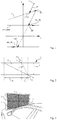
- FIG. 1 A sketch of the approach for two planes is given by Figure 1 .
- the windhshield pane is denoted with the reference numeral 1.
- Lens systems can be modelled by chains of planes in commercial optical system simulations. In the state of the art, these planes are parallel to each other and to the imager plane. For the purpose of the invention, however, this rule is not followed.
- the previously introduced generalized camera model is a simple instance of such an approach. To observe this, as a special case no shift at all at the windshield plane 1 shall be considered.
- the purpose of the camera model is, as mentioned above, to explain how a point in space is mapped to a point in the image.
- a new camera model w R 3 ⁇ R m ⁇ R 2 is introduced.
- equation (15) can not be expected to have a closed form solution. In fact, it can not be expected for equation (15) to have a solution at all, which satisfies all requirements.
- equation (15) it is discussed how the generalized pinhole camera equations can be adapted in the positive case. Consecutively, a particular case is discussed, where the existence can be shown.
- the generalized central projection ⁇ s ⁇ u x s , u y s is introduced. It has not yet been shown that such u exists at all.
- the projection ⁇ is inherently parameteric, as it introduces properties of the windshield into the projection property of the camera.
- the new parameters of ⁇ are referred to as the windshield parameters.
- the camera calibration procedures merely use the projection property of the camera.
- depth dependency as described above is not an issue for such methods.
- ADAS application software applies the inverse procedure to projection.
- Depth dependency in the above sense poses at first glance a challenge, when it comes to extending existing software solutions by the new model. Fortunately, there is an approximation of the general model, which approximates an image transformation introduced by the scene and, hence, admits inverse projection.
- one aspect of the invention is directed at a method of calibrating a camera-based system of a vehicle - preferably an ADAS system - comprising the steps of acquiring an image with the camera, and then calculating, using the windshield distortion, the set of points in space that is projected to a location on the image. This can be seen as the inverse procedure to projection.
- the above approximate model is merely a restriction of the full model, which works perfectly for objects at the distance z and degrades gradually, when the real coordinate s z moves away from z .
- the total distortion of the camera-based system is yielded as composition - preferably a sum - of a radial distortion of the camera and a tangential distortion of the camera and the windshield distortion introduced by the windshield.
- the newly developed windshield distortion component h can easily be introduced into currently available ADAS systems .
- One aspect of the invention consequently regards a model for calibration of a camera-based system, where each set of points which are mapped on a single image location lies on a straight (virtual) line, where all the straight lines intersect in a single point, being the pinhole of the camera according to the pinhole model.
- the set of points here may refer to the points v according to equation 29.
- one further aspect of the invention is directed at a method for image rectification, where the set of points that is projected on a single location in the image is calculated by applying the windshield distortion - which was introduced onto an acquired image of a target in a fixed distance z - on all points v in any distance s z .
- the complete 3D location of an object can be determined by triangulation using at least two images acquired at different locations. These images can be acquired by a single moving camera, or by a stereo camera system comprising two cameras that are preferably oriented parallelly to each other.
- FIG. 2 shows a physically motivated low curvature windshield model, where the optical ray is shifted along the glass surface.
- the refraction on this model is governed by Snell's law.
- v with 0 ⁇ v ⁇ R is the refraction index of the medium.
- the transmission of a light ray through the windshield does not change the ray's direction.
- the ray is merely shifted along the surface of the windshield. That is, the assumption of a shift along the plane is entirely motivated by optics. Equivalently to the physical model, the shift is performed only on one of the surfaces, in particular on the incident surface.
- the windshield is typically pitched with respect to the viewing direction of the camera. Other angles appear insignificant compared to the pitch.
- Figure 2 shows only a cross section of the corresponding shift along u.
- Latter behaviour can be approximated by assuming that the shift occurs only in the direction parallel to the optical axis of the camera. More precisely, it is assumed that ⁇ s u ⁇ 0 , sin ⁇ , cos ⁇ .
- the windshield plane models the physics of a flat glass model pitched with respect to the local camera coordinate system by ⁇ .
- one aspect of the invention is directed at a method of calibrating a camera-based system, where the windshield distortion is calculated by approximating that the distortion of rays through be windshield occurs only in the plane that is constructed by the optical axis of the camera and the vertical axis.
- “Vertical” means the direction of gravity.
- the next step is to apply narrow angle approximations, to get rid of trigonometric functions in the definition of h and ⁇ . Therefore, sin( x ), tan( x ), and tan -1 ( x ) are approximated by x , whenever required. In particular, from equation (32) with the above approximation it is obtained that ⁇ ⁇ ⁇ / v .
- one aspect of the invention is directed at a method of calibrating a camera-based system, where the windshield distortion is calculated by approximating the sine of an angle ⁇ between a ray from a point on the calibration target to a point on the windshield pane and the normal on that point to the windshield pane with that angle ⁇ .
- This allows for an otherwise unavailable method of calibration and rectification, as shown below.
- one aspect of the invention relates to a method of storing in the camera-based system a mapping of a point in space and of physical parameters of the windshield pane to locations on an calibration image acquired with the camera.
- mapping may be stored, i.e. a mapping of locations on an image acquired with the camera and of physical parameters of the windshield to a sets of points in space, where this transformation depends on the calculated windshield distortion.
- This mapping is given by an inversion of the above equations, which may or must be carried out numerically in practice.
- this allows for an analytically precise modelling and rectification of the distortion introduced by a windshield pane with the respective physical parameters.
- the invention also relates to an apparatus for compensation of static image distortions introduced by a windshield for an ADAS camera.
- a setup for plane calibration can be transformed to a method for windshield calibration.
- One assumption may be that a camera is provided, which is intrinsically calibrated elsewhere. Moreover, multiple windshields are provided, to which the particular camera can be attached subsequently. The windshields can be placed in a stand or directly in the vehicle.
- Figure 3 shows an embodiment of the invention where a single-plane target 2 is is put in front of the camera (not pictured).
- the target contains a regular pattern, for example with checkers, from which one middle section 5 has a special form to be easily recognized.
- the target is placed in a way that the pattern covers the entire image of the camera.
- Pictured is an apparatus for calibration of a camera-based system - not shown in detail - of a vehicle 3 including a windshield pane (not pictured).
- the apparatus in this case comprises a vehicle with a windshield pane which is installed in the windshield bracket of the vehicle.
- a camera - not explicitly shown - that is preferably mounted on the backside of an inside rear mirror (not pictured) is facing the windshield pane from a first side, being inside the vehicle 3, and a target 2 in form of board with a known pattern 4 is mounted in a fixed distance z (not explicitly marked) on the other side (outside of the vehicle) of the windshield inside a field of view of the camera, such that the camera can acquire an image of the target 2 through the windshield.
- the vehicle also includes a computing unit (not shown) which comprises program code which, when run by the computing unit, executes a method as described above.
- this allows for the first time for calibration of a camera inside the vehicle 3 instead of inside a dedicated optical setup, i.e. inside a laboratory.
- the calibration procedure can be carried out in standard manner with the new model in equation (22), as explained previously.
- the intrinsic parameters of the camera may be treated as constants to retain ambiguity.
- the parameters of the windshield are estimated along with the extrinsic parameters.
- the calibration can be performed at relatively narrow distances. In such distances, the effects of windshield distortions are more pronounced. Consequently, the calibration of the windshield parameters is well applicable in this case.
- the proposed setup can be applied to estimate the average windshield parameters for a set of a number of similar windshields for a vehicle. For example, one stereo camera can be used and the windshield parameters for the left and for the right optic modules of the camera can be estimated separately. The average windshield parameters estimated for each optic module separately can then be applied to compensate the windshield distortions on a recorded test driving sequence.
- the windshield can be kept in a stand at approximately 30 degrees to the target.
- the camera can be mounted to the windshield in the vehicle bracket on the windshield.
- the optical axis of the camera can be oriented approximately perpendicular to the target.
- the windshield calibration parameters for one of the optic modules can be obtained. These parameters can preferably be - but are not limited to - the tilt ⁇ , the thickness t and/or the refraction index v of the windshield pane.
- the invention also comprises a method of determining physical parameters of the windshield pane by interpreting the windshield distortion.
- the averaged parameters can be used approximately for any of the windshields of the same form. Also, it could be checked that the windshield panes do not differ in their parameters.
Landscapes
- Engineering & Computer Science (AREA)
- Computer Vision & Pattern Recognition (AREA)
- Physics & Mathematics (AREA)
- General Physics & Mathematics (AREA)
- Theoretical Computer Science (AREA)
- Length Measuring Devices By Optical Means (AREA)
Claims (15)
- Procédé d'étalonnage d'un système basé sur une caméra d'un véhicule ayant une glace de pare-brise, le procédé comprenant les étapes consistant :à placer une cible d'imagerie sous la forme d'un panneau ayant un motif connu dans le champ de vision d'une caméra du système basé sur une caméra de telle sorte que la caméra puisse acquérir une image d'étalonnage du panneau à travers la glace de pare-brise,à acquérir exactement une image d'étalonnage du panneau avec la caméra,à comparer l'image d'étalonnage avec le motif connu,à calculer une déformation de pare-brise qui est introduite par la glace de pare-brise, à l'aide d'un modèle de caméra comprenant des paramètres représentant des propriétés de déformation du pare-brise, dans lequel les paramètres intrinsèques de la caméra sont connus, età stocker la déformation de pare-brise dans le système basé sur une caméra.
- Procédé selon la revendication 1, comprenant les étapes consistant :à calculer une déformation totale du système basé sur une caméra en tant que composition d'une déformation radiale de la caméra et d'une déformation tangentielle de la caméra et de la déformation de pare-brise, età stocker la déformation totale du système basé sur une caméra dans le système basé sur une caméra.
- Procédé selon l'une quelconque des revendications précédentes, dans lequel le calcul de la déformation de pare-brise consiste à approximer un sinus d'un angle entre un rayon depuis un point sur la cible d'étalonnage jusqu'à un point sur la glace de pare-brise et une normale sur ce point par rapport à la glace de pare-brise avec cet angle.
- Procédé selon l'une quelconque des revendications précédentes, dans lequel le calcul de la déformation de pare-brise consiste à estimer que la déformation de rayons à travers la glace de pare-brise se produit seulement dans un plan qui est construit par un axe optique de la caméra et un axe vertical.
- Procédé selon l'une quelconque des revendications précédentes, où la déformation de pare-brise est donnée par h = (hx, hy ) = (vz (vz + δz (v, u(v))))-1 (vzδx (v, u(v)) - vxδz (v, u(v)), vzδy (v, u(v)) - vyδz (v, u(v)))
avec un décalage le long d'un plan de pare-brise δ = (δx, δy, δz ), dans lequel le plan de pare-brise est un plan fixe supplémentaire dans le système de coordonnées locales, un emplacement projeté sur l'image u(v) = (u x, u y, 1), un point dans l'espace s = (sx, sy, sz ) et un vecteur v = z(s x /sz, sy /sz, 1) et une distance fixe z = vz, dans lequel la distance z est approximativement sz . - Procédé selon la revendication 1, comprenant l'étape consistant à déterminer et/ou à estimer des paramètres physiques de la glace de pare-brise en interprétant la déformation de pare-brise.
- Procédé selon la revendication 6, où les paramètres physiques sont une inclinaison et/ou un indice de réfraction et/ou une épaisseur de la glace de pare-brise.
- Procédé selon l'une quelconque des revendications 6 et 7, comprenant l'étape consistant :
à stocker, dans le système basé sur une caméra, une mise en correspondance d'un point dans l'espace et de paramètres physiques de la glace de pare-brise avec des emplacements sur une image acquise avec la caméra. - Procédé selon la revendication 8, où la mise en correspondance comprend une transformation


- Système basé sur une caméra pour un véhicule comprenant une caméra et une unité de calcul, qui comprend un code de programme qui, lorsqu'il est exécuté par l'unité de calcul, exécute un procédé d'étalonnage du système basé sur une caméra en acquérant exactement une image d'étalonnage d'un panneau ayant un motif connu avec la caméra, en comparant l'image d'étalonnage avec le motif connu, en calculant une déformation de pare-brise qui est introduite par une glace de pare-brise entre la caméra et le panneau à l'aide d'un modèle de caméra comprenant des paramètres représentant des propriétés de déformation du pare-brise, dans lequel les paramètres intrinsèques de la caméra sont connus, et en stockant la déformation de pare-brise dans le système basé sur une caméra.
- Appareil d'étalonnage d'un système basé sur une caméra d'un véhicule ayant une glace de pare-brise, comprenant un système basé sur une caméra selon la revendication 10, dans lequel la caméra fait face à la glace de pare-brise depuis un premier côté de la glace de pare-brise, l'appareil comprenant un panneau ayant un motif connu qui est monté à une distance fixe z sur un second côté de la glace de pare-brise à l'intérieur d'un champ de vision de la caméra, de telle sorte que la caméra puisse acquérir une image d'étalonnage du panneau à travers la glace de pare-brise.
- Appareil selon la revendication 11 comprenant un véhicule ayant un cadre de pare-brise, où la glace de pare-brise est installée dans le cadre de pare-brise du véhicule et la caméra est montée à l'intérieur du véhicule.
- Procédé de rectification d'images acquises par au moins une caméra d'un système basé sur une caméra d'un véhicule ayant une glace de pare-brise, le procédé comprenant les étapes consistant :à étalonner le système basé sur une caméra à l'aide d'un procédé selon l'une des revendications 1 à 9,à acquérir une image avec la caméra, età calculer, à l'aide de la déformation de pare-brise stockée dans le système basé sur une caméra, un ensemble de points dans l'espace qui est projeté vers un emplacement sur l'image.
- Procédé selon la revendication 13, où un emplacement en 3D d'un objet est déterminé par triangulation à l'aide d'au moins deux images acquises à des emplacements différents.
- Système basé sur une caméra comprenant une unité de calcul qui comprend un code de programme qui, lorsqu'il est exécuté par l'unité de calcul, exécute un procédé selon l'une quelconque des revendications 13 et 14.
Priority Applications (2)
| Application Number | Priority Date | Filing Date | Title |
|---|---|---|---|
| ES16187553T ES2762867T3 (es) | 2016-09-07 | 2016-09-07 | Procedimiento y aparato para la compensación de distorsiones de imágenes estáticas introducidas por un parabrisas en una cámara ADAS |
| EP16187553.9A EP3293701B1 (fr) | 2016-09-07 | 2016-09-07 | Procédé et appareil pour la compensation de distorsions d'images statiques introduites par un parebrise sur une caméra d'aide à la conduite automobile |
Applications Claiming Priority (1)
| Application Number | Priority Date | Filing Date | Title |
|---|---|---|---|
| EP16187553.9A EP3293701B1 (fr) | 2016-09-07 | 2016-09-07 | Procédé et appareil pour la compensation de distorsions d'images statiques introduites par un parebrise sur une caméra d'aide à la conduite automobile |
Publications (2)
| Publication Number | Publication Date |
|---|---|
| EP3293701A1 EP3293701A1 (fr) | 2018-03-14 |
| EP3293701B1 true EP3293701B1 (fr) | 2019-11-06 |
Family
ID=56943321
Family Applications (1)
| Application Number | Title | Priority Date | Filing Date |
|---|---|---|---|
| EP16187553.9A Active EP3293701B1 (fr) | 2016-09-07 | 2016-09-07 | Procédé et appareil pour la compensation de distorsions d'images statiques introduites par un parebrise sur une caméra d'aide à la conduite automobile |
Country Status (2)
| Country | Link |
|---|---|
| EP (1) | EP3293701B1 (fr) |
| ES (1) | ES2762867T3 (fr) |
Cited By (3)
| Publication number | Priority date | Publication date | Assignee | Title |
|---|---|---|---|---|
| EP3982328A1 (fr) | 2020-10-08 | 2022-04-13 | Saint-Gobain Glass France | Procédé de simulation des effets des distorsions optiques d'un pare-brise sur la qualité d'enregistrement des images d'un dispositif d'enregistrement d'images numériques |
| DE102021214040B3 (de) | 2021-12-09 | 2023-05-04 | Continental Autonomous Mobility Germany GmbH | Dynamische Autokalibrierung eines Fahrzeugkamerasystems hinter einer Scheibe |
| US12117405B2 (en) | 2019-09-13 | 2024-10-15 | Acr Ii Glass America Inc. | Method and system for providing optical distortion information of a vehicle glazing |
Families Citing this family (11)
| Publication number | Priority date | Publication date | Assignee | Title |
|---|---|---|---|---|
| GB201904203D0 (en) | 2019-03-26 | 2019-05-08 | Pikington Group Ltd | Laminated glazing and process |
| WO2021004642A1 (fr) * | 2019-07-11 | 2021-01-14 | Toyota Motor Europe | Procédé d'étalonnage de caméra, programme informatique, support d'enregistrement lisible par ordinateur et système d'étalonnage de caméra |
| CN111080720B (zh) * | 2019-12-26 | 2023-07-04 | 重庆盟讯电子科技有限公司 | 一种模组校正方法 |
| DE102020211154A1 (de) | 2020-09-04 | 2022-03-10 | Robert Bosch Gesellschaft mit beschränkter Haftung | Verfahren und Vorrichtung zum Kalibrieren einer in einem Fahrzeug montierten Kamera |
| DE102020215417A1 (de) * | 2020-12-07 | 2022-06-09 | Robert Bosch Gesellschaft mit beschränkter Haftung | Verfahren zum Vermessen des Einflusses einer transparenten Scheibe |
| EP4016444B1 (fr) | 2020-12-15 | 2025-06-18 | Continental Autonomous Mobility Germany GmbH | Procédé de rectification d'images et/ou de points d'image, système par caméra et véhicule |
| FR3124782B1 (fr) * | 2021-06-30 | 2023-12-08 | Saint Gobain | Méthode d’analyse de la qualité optique d’un vitrage, méthode de calibration d’une caméra, vitrage analysé |
| CN117981298A (zh) * | 2021-09-24 | 2024-05-03 | 苹果公司 | 对象定位和信息编码系统 |
| EP4170327A1 (fr) * | 2021-10-22 | 2023-04-26 | Saint-Gobain Glass France | Procédé et système de détection des défauts optiques dans un pare-brise en verre |
| JP7786941B2 (ja) * | 2021-12-27 | 2025-12-16 | Astemo株式会社 | カメラの校正方法 |
| WO2026013780A1 (fr) * | 2024-07-10 | 2026-01-15 | Astemo株式会社 | Dispositif d'étalonnage de caméra et procédé d'étalonnage de caméra |
Family Cites Families (3)
| Publication number | Priority date | Publication date | Assignee | Title |
|---|---|---|---|---|
| DE10246066B4 (de) * | 2002-10-02 | 2007-11-22 | Robert Bosch Gmbh | Verfahren und Vorrichtung zur Kalibrierung eines Bildsensorsystems in einem Kraftfahrzeug |
| JP6427900B2 (ja) * | 2014-03-07 | 2018-11-28 | 株式会社リコー | 校正方法、校正システム、プログラム及び移動体 |
| FR3032820B1 (fr) * | 2015-02-18 | 2017-02-10 | Continental Automotive France | Procede de calibration d'une camera montee sur le pare-brise d'un vehicule |
-
2016
- 2016-09-07 EP EP16187553.9A patent/EP3293701B1/fr active Active
- 2016-09-07 ES ES16187553T patent/ES2762867T3/es active Active
Non-Patent Citations (1)
| Title |
|---|
| None * |
Cited By (5)
| Publication number | Priority date | Publication date | Assignee | Title |
|---|---|---|---|---|
| US12117405B2 (en) | 2019-09-13 | 2024-10-15 | Acr Ii Glass America Inc. | Method and system for providing optical distortion information of a vehicle glazing |
| EP3982328A1 (fr) | 2020-10-08 | 2022-04-13 | Saint-Gobain Glass France | Procédé de simulation des effets des distorsions optiques d'un pare-brise sur la qualité d'enregistrement des images d'un dispositif d'enregistrement d'images numériques |
| DE102021214040B3 (de) | 2021-12-09 | 2023-05-04 | Continental Autonomous Mobility Germany GmbH | Dynamische Autokalibrierung eines Fahrzeugkamerasystems hinter einer Scheibe |
| WO2023104254A1 (fr) | 2021-12-09 | 2023-06-15 | Continental Autonomous Mobility Germany GmbH | Auto-étalonnage dynamique d'un système de prise de vues de véhicule derrière un pare-brise |
| US12437444B2 (en) | 2021-12-09 | 2025-10-07 | Continental Autonomous Mobility Germany GmbH | Dynamic autocalibration of a vehicle camera system behind a windshield |
Also Published As
| Publication number | Publication date |
|---|---|
| ES2762867T3 (es) | 2020-05-26 |
| EP3293701A1 (fr) | 2018-03-14 |
Similar Documents
| Publication | Publication Date | Title |
|---|---|---|
| EP3293701B1 (fr) | Procédé et appareil pour la compensation de distorsions d'images statiques introduites par un parebrise sur une caméra d'aide à la conduite automobile | |
| Schops et al. | Why having 10,000 parameters in your camera model is better than twelve | |
| Jordt-Sedlazeck et al. | Refractive calibration of underwater cameras | |
| US10909395B2 (en) | Object detection apparatus | |
| CN116433737B (zh) | 一种激光雷达点云与图像配准的方法、装置及智能终端 | |
| US11985292B1 (en) | Residual error mitigation in multiview calibration | |
| CN117237789B (zh) | 基于全景相机和激光雷达融合生成纹理信息点云地图方法 | |
| Zhang et al. | Depth sensing beyond lidar range | |
| CN101467153A (zh) | 用于获取摄影测量数据来估计碰撞严重性的方法和设备 | |
| CN111971956B (zh) | 用于动态立体校准的方法及系统 | |
| Kondermann et al. | Stereo ground truth with error bars | |
| Fathi et al. | Multistep explicit stereo camera calibration approach to improve Euclidean accuracy of large-scale 3D reconstruction | |
| Ding et al. | A robust detection method of control points for calibration and measurement with defocused images | |
| US20200088508A1 (en) | Three-dimensional information generating device and method capable of self-calibration | |
| García-Moreno et al. | Error propagation and uncertainty analysis between 3D laser scanner and camera | |
| KR102803378B1 (ko) | 이미지 및/또는 이미지 지점의 보정 방법, 카메라 기반 시스템 및 차량 | |
| Long et al. | Portable visual metrology without traditional self-calibration measurement model | |
| CN111462321B (zh) | 点云地图处理方法、处理装置、电子装置和车辆 | |
| JP7778928B2 (ja) | ガラス裏側の車両カメラシステムの動的自動較正 | |
| Yin et al. | Eccentricity compensation for multi-view circle positioning based on geometric constraints | |
| US20260011159A1 (en) | Road surface three-dimensional shape estimation device, road surface three-dimensional shape estimation method, road surface three-dimensional shape estimation system, and road surface three-dimensional shape estimation program | |
| Nekouei Shahraki | Design and development of a calibration solution feasible for series production of cameras for video-based driver-assistant systems | |
| Tekla et al. | A Minimal Solution for Image-Based Sphere Estimation | |
| Blessing et al. | Time-efficient intrinsic calibration of an automotive lidar sensor using a tabletop setup to reach subpixel precision | |
| Wang et al. | Refraction correction and calibration for planar structured light system in underwater environment: an improved ray tracing method based on projection and mapping |
Legal Events
| Date | Code | Title | Description |
|---|---|---|---|
| PUAI | Public reference made under article 153(3) epc to a published international application that has entered the european phase |
Free format text: ORIGINAL CODE: 0009012 |
|
| STAA | Information on the status of an ep patent application or granted ep patent |
Free format text: STATUS: THE APPLICATION HAS BEEN PUBLISHED |
|
| AK | Designated contracting states |
Kind code of ref document: A1 Designated state(s): AL AT BE BG CH CY CZ DE DK EE ES FI FR GB GR HR HU IE IS IT LI LT LU LV MC MK MT NL NO PL PT RO RS SE SI SK SM TR |
|
| AX | Request for extension of the european patent |
Extension state: BA ME |
|
| STAA | Information on the status of an ep patent application or granted ep patent |
Free format text: STATUS: REQUEST FOR EXAMINATION WAS MADE |
|
| 17P | Request for examination filed |
Effective date: 20180914 |
|
| RBV | Designated contracting states (corrected) |
Designated state(s): AL AT BE BG CH CY CZ DE DK EE ES FI FR GB GR HR HU IE IS IT LI LT LU LV MC MK MT NL NO PL PT RO RS SE SI SK SM TR |
|
| STAA | Information on the status of an ep patent application or granted ep patent |
Free format text: STATUS: EXAMINATION IS IN PROGRESS |
|
| 17Q | First examination report despatched |
Effective date: 20181109 |
|
| GRAP | Despatch of communication of intention to grant a patent |
Free format text: ORIGINAL CODE: EPIDOSNIGR1 |
|
| STAA | Information on the status of an ep patent application or granted ep patent |
Free format text: STATUS: GRANT OF PATENT IS INTENDED |
|
| INTG | Intention to grant announced |
Effective date: 20190528 |
|
| GRAS | Grant fee paid |
Free format text: ORIGINAL CODE: EPIDOSNIGR3 |
|
| GRAA | (expected) grant |
Free format text: ORIGINAL CODE: 0009210 |
|
| STAA | Information on the status of an ep patent application or granted ep patent |
Free format text: STATUS: THE PATENT HAS BEEN GRANTED |
|
| AK | Designated contracting states |
Kind code of ref document: B1 Designated state(s): AL AT BE BG CH CY CZ DE DK EE ES FI FR GB GR HR HU IE IS IT LI LT LU LV MC MK MT NL NO PL PT RO RS SE SI SK SM TR |
|
| REG | Reference to a national code |
Ref country code: GB Ref legal event code: FG4D |
|
| REG | Reference to a national code |
Ref country code: CH Ref legal event code: EP Ref country code: AT Ref legal event code: REF Ref document number: 1199817 Country of ref document: AT Kind code of ref document: T Effective date: 20191115 |
|
| REG | Reference to a national code |
Ref country code: IE Ref legal event code: FG4D |
|
| REG | Reference to a national code |
Ref country code: DE Ref legal event code: R096 Ref document number: 602016023653 Country of ref document: DE |
|
| REG | Reference to a national code |
Ref country code: NL Ref legal event code: MP Effective date: 20191106 |
|
| REG | Reference to a national code |
Ref country code: LT Ref legal event code: MG4D |
|
| PG25 | Lapsed in a contracting state [announced via postgrant information from national office to epo] |
Ref country code: BG Free format text: LAPSE BECAUSE OF FAILURE TO SUBMIT A TRANSLATION OF THE DESCRIPTION OR TO PAY THE FEE WITHIN THE PRESCRIBED TIME-LIMIT Effective date: 20200206 Ref country code: FI Free format text: LAPSE BECAUSE OF FAILURE TO SUBMIT A TRANSLATION OF THE DESCRIPTION OR TO PAY THE FEE WITHIN THE PRESCRIBED TIME-LIMIT Effective date: 20191106 Ref country code: NO Free format text: LAPSE BECAUSE OF FAILURE TO SUBMIT A TRANSLATION OF THE DESCRIPTION OR TO PAY THE FEE WITHIN THE PRESCRIBED TIME-LIMIT Effective date: 20200206 Ref country code: GR Free format text: LAPSE BECAUSE OF FAILURE TO SUBMIT A TRANSLATION OF THE DESCRIPTION OR TO PAY THE FEE WITHIN THE PRESCRIBED TIME-LIMIT Effective date: 20200207 Ref country code: PL Free format text: LAPSE BECAUSE OF FAILURE TO SUBMIT A TRANSLATION OF THE DESCRIPTION OR TO PAY THE FEE WITHIN THE PRESCRIBED TIME-LIMIT Effective date: 20191106 Ref country code: LV Free format text: LAPSE BECAUSE OF FAILURE TO SUBMIT A TRANSLATION OF THE DESCRIPTION OR TO PAY THE FEE WITHIN THE PRESCRIBED TIME-LIMIT Effective date: 20191106 Ref country code: SE Free format text: LAPSE BECAUSE OF FAILURE TO SUBMIT A TRANSLATION OF THE DESCRIPTION OR TO PAY THE FEE WITHIN THE PRESCRIBED TIME-LIMIT Effective date: 20191106 Ref country code: PT Free format text: LAPSE BECAUSE OF FAILURE TO SUBMIT A TRANSLATION OF THE DESCRIPTION OR TO PAY THE FEE WITHIN THE PRESCRIBED TIME-LIMIT Effective date: 20200306 Ref country code: LT Free format text: LAPSE BECAUSE OF FAILURE TO SUBMIT A TRANSLATION OF THE DESCRIPTION OR TO PAY THE FEE WITHIN THE PRESCRIBED TIME-LIMIT Effective date: 20191106 Ref country code: NL Free format text: LAPSE BECAUSE OF FAILURE TO SUBMIT A TRANSLATION OF THE DESCRIPTION OR TO PAY THE FEE WITHIN THE PRESCRIBED TIME-LIMIT Effective date: 20191106 |
|
| REG | Reference to a national code |
Ref country code: ES Ref legal event code: FG2A Ref document number: 2762867 Country of ref document: ES Kind code of ref document: T3 Effective date: 20200526 |
|
| PG25 | Lapsed in a contracting state [announced via postgrant information from national office to epo] |
Ref country code: IS Free format text: LAPSE BECAUSE OF FAILURE TO SUBMIT A TRANSLATION OF THE DESCRIPTION OR TO PAY THE FEE WITHIN THE PRESCRIBED TIME-LIMIT Effective date: 20200306 Ref country code: HR Free format text: LAPSE BECAUSE OF FAILURE TO SUBMIT A TRANSLATION OF THE DESCRIPTION OR TO PAY THE FEE WITHIN THE PRESCRIBED TIME-LIMIT Effective date: 20191106 Ref country code: RS Free format text: LAPSE BECAUSE OF FAILURE TO SUBMIT A TRANSLATION OF THE DESCRIPTION OR TO PAY THE FEE WITHIN THE PRESCRIBED TIME-LIMIT Effective date: 20191106 |
|
| PG25 | Lapsed in a contracting state [announced via postgrant information from national office to epo] |
Ref country code: AL Free format text: LAPSE BECAUSE OF FAILURE TO SUBMIT A TRANSLATION OF THE DESCRIPTION OR TO PAY THE FEE WITHIN THE PRESCRIBED TIME-LIMIT Effective date: 20191106 |
|
| PG25 | Lapsed in a contracting state [announced via postgrant information from national office to epo] |
Ref country code: DK Free format text: LAPSE BECAUSE OF FAILURE TO SUBMIT A TRANSLATION OF THE DESCRIPTION OR TO PAY THE FEE WITHIN THE PRESCRIBED TIME-LIMIT Effective date: 20191106 Ref country code: EE Free format text: LAPSE BECAUSE OF FAILURE TO SUBMIT A TRANSLATION OF THE DESCRIPTION OR TO PAY THE FEE WITHIN THE PRESCRIBED TIME-LIMIT Effective date: 20191106 Ref country code: CZ Free format text: LAPSE BECAUSE OF FAILURE TO SUBMIT A TRANSLATION OF THE DESCRIPTION OR TO PAY THE FEE WITHIN THE PRESCRIBED TIME-LIMIT Effective date: 20191106 Ref country code: RO Free format text: LAPSE BECAUSE OF FAILURE TO SUBMIT A TRANSLATION OF THE DESCRIPTION OR TO PAY THE FEE WITHIN THE PRESCRIBED TIME-LIMIT Effective date: 20191106 |
|
| REG | Reference to a national code |
Ref country code: DE Ref legal event code: R097 Ref document number: 602016023653 Country of ref document: DE |
|
| REG | Reference to a national code |
Ref country code: AT Ref legal event code: MK05 Ref document number: 1199817 Country of ref document: AT Kind code of ref document: T Effective date: 20191106 |
|
| PG25 | Lapsed in a contracting state [announced via postgrant information from national office to epo] |
Ref country code: SM Free format text: LAPSE BECAUSE OF FAILURE TO SUBMIT A TRANSLATION OF THE DESCRIPTION OR TO PAY THE FEE WITHIN THE PRESCRIBED TIME-LIMIT Effective date: 20191106 Ref country code: SK Free format text: LAPSE BECAUSE OF FAILURE TO SUBMIT A TRANSLATION OF THE DESCRIPTION OR TO PAY THE FEE WITHIN THE PRESCRIBED TIME-LIMIT Effective date: 20191106 |
|
| PLBE | No opposition filed within time limit |
Free format text: ORIGINAL CODE: 0009261 |
|
| STAA | Information on the status of an ep patent application or granted ep patent |
Free format text: STATUS: NO OPPOSITION FILED WITHIN TIME LIMIT |
|
| 26N | No opposition filed |
Effective date: 20200807 |
|
| PG25 | Lapsed in a contracting state [announced via postgrant information from national office to epo] |
Ref country code: AT Free format text: LAPSE BECAUSE OF FAILURE TO SUBMIT A TRANSLATION OF THE DESCRIPTION OR TO PAY THE FEE WITHIN THE PRESCRIBED TIME-LIMIT Effective date: 20191106 Ref country code: SI Free format text: LAPSE BECAUSE OF FAILURE TO SUBMIT A TRANSLATION OF THE DESCRIPTION OR TO PAY THE FEE WITHIN THE PRESCRIBED TIME-LIMIT Effective date: 20191106 |
|
| REG | Reference to a national code |
Ref country code: CH Ref legal event code: PL |
|
| REG | Reference to a national code |
Ref country code: BE Ref legal event code: MM Effective date: 20200930 |
|
| PG25 | Lapsed in a contracting state [announced via postgrant information from national office to epo] |
Ref country code: LU Free format text: LAPSE BECAUSE OF NON-PAYMENT OF DUE FEES Effective date: 20200907 |
|
| PG25 | Lapsed in a contracting state [announced via postgrant information from national office to epo] |
Ref country code: BE Free format text: LAPSE BECAUSE OF NON-PAYMENT OF DUE FEES Effective date: 20200930 Ref country code: CH Free format text: LAPSE BECAUSE OF NON-PAYMENT OF DUE FEES Effective date: 20200930 Ref country code: IE Free format text: LAPSE BECAUSE OF NON-PAYMENT OF DUE FEES Effective date: 20200907 Ref country code: LI Free format text: LAPSE BECAUSE OF NON-PAYMENT OF DUE FEES Effective date: 20200930 |
|
| PG25 | Lapsed in a contracting state [announced via postgrant information from national office to epo] |
Ref country code: TR Free format text: LAPSE BECAUSE OF FAILURE TO SUBMIT A TRANSLATION OF THE DESCRIPTION OR TO PAY THE FEE WITHIN THE PRESCRIBED TIME-LIMIT Effective date: 20191106 Ref country code: MT Free format text: LAPSE BECAUSE OF FAILURE TO SUBMIT A TRANSLATION OF THE DESCRIPTION OR TO PAY THE FEE WITHIN THE PRESCRIBED TIME-LIMIT Effective date: 20191106 Ref country code: CY Free format text: LAPSE BECAUSE OF FAILURE TO SUBMIT A TRANSLATION OF THE DESCRIPTION OR TO PAY THE FEE WITHIN THE PRESCRIBED TIME-LIMIT Effective date: 20191106 |
|
| REG | Reference to a national code |
Ref country code: DE Ref legal event code: R081 Ref document number: 602016023653 Country of ref document: DE Owner name: CONTINENTAL AUTONOMOUS MOBILITY GERMANY GMBH, DE Free format text: FORMER OWNER: CONTI TEMIC MICROELECTRONIC GMBH, 90411 NUERNBERG, DE Ref country code: DE Ref legal event code: R081 Ref document number: 602016023653 Country of ref document: DE Owner name: AUMOVIO AUTONOMOUS MOBILITY GERMANY GMBH, DE Free format text: FORMER OWNER: CONTI TEMIC MICROELECTRONIC GMBH, 90411 NUERNBERG, DE |
|
| PG25 | Lapsed in a contracting state [announced via postgrant information from national office to epo] |
Ref country code: MK Free format text: LAPSE BECAUSE OF FAILURE TO SUBMIT A TRANSLATION OF THE DESCRIPTION OR TO PAY THE FEE WITHIN THE PRESCRIBED TIME-LIMIT Effective date: 20191106 Ref country code: MC Free format text: LAPSE BECAUSE OF FAILURE TO SUBMIT A TRANSLATION OF THE DESCRIPTION OR TO PAY THE FEE WITHIN THE PRESCRIBED TIME-LIMIT Effective date: 20191106 |
|
| REG | Reference to a national code |
Ref country code: GB Ref legal event code: 732E Free format text: REGISTERED BETWEEN 20240321 AND 20240327 |
|
| REG | Reference to a national code |
Ref country code: ES Ref legal event code: PC2A Owner name: CONTINENTAL AUTONOMOUS MOBILITY GERMANY GMBH Effective date: 20241007 |
|
| REG | Reference to a national code |
Ref country code: DE Ref legal event code: R081 Ref document number: 602016023653 Country of ref document: DE Owner name: AUMOVIO AUTONOMOUS MOBILITY GERMANY GMBH, DE Free format text: FORMER OWNER: CONTINENTAL AUTONOMOUS MOBILITY GERMANY GMBH, 85057 INGOLSTADT, DE |
|
| PGFP | Annual fee paid to national office [announced via postgrant information from national office to epo] |
Ref country code: DE Payment date: 20250930 Year of fee payment: 10 |
|
| PGFP | Annual fee paid to national office [announced via postgrant information from national office to epo] |
Ref country code: IT Payment date: 20250923 Year of fee payment: 10 |
|
| PGFP | Annual fee paid to national office [announced via postgrant information from national office to epo] |
Ref country code: GB Payment date: 20250919 Year of fee payment: 10 |
|
| PGFP | Annual fee paid to national office [announced via postgrant information from national office to epo] |
Ref country code: FR Payment date: 20250922 Year of fee payment: 10 |
|
| PGFP | Annual fee paid to national office [announced via postgrant information from national office to epo] |
Ref country code: ES Payment date: 20251028 Year of fee payment: 10 |
|
| REG | Reference to a national code |
Ref country code: DE Ref legal event code: R084 Ref document number: 602016023653 Country of ref document: DE |