EP3293842A1 - Cadre de montage d'appareil électrique - Google Patents
Cadre de montage d'appareil électrique Download PDFInfo
- Publication number
- EP3293842A1 EP3293842A1 EP17190656.3A EP17190656A EP3293842A1 EP 3293842 A1 EP3293842 A1 EP 3293842A1 EP 17190656 A EP17190656 A EP 17190656A EP 3293842 A1 EP3293842 A1 EP 3293842A1
- Authority
- EP
- European Patent Office
- Prior art keywords
- central opening
- electrical apparatus
- frame
- cross members
- mounting
- Prior art date
- Legal status (The legal status is an assumption and is not a legal conclusion. Google has not performed a legal analysis and makes no representation as to the accuracy of the status listed.)
- Withdrawn
Links
Images


Classifications
-
- H—ELECTRICITY
- H02—GENERATION; CONVERSION OR DISTRIBUTION OF ELECTRIC POWER
- H02G—INSTALLATION OF ELECTRIC CABLES OR LINES, OR OF COMBINED OPTICAL AND ELECTRIC CABLES OR LINES
- H02G3/00—Installations of electric cables or lines or protective tubing therefor in or on buildings, equivalent structures or vehicles
- H02G3/02—Details
- H02G3/08—Distribution boxes; Connection or junction boxes
- H02G3/086—Assembled boxes
-
- H—ELECTRICITY
- H02—GENERATION; CONVERSION OR DISTRIBUTION OF ELECTRIC POWER
- H02G—INSTALLATION OF ELECTRIC CABLES OR LINES, OR OF COMBINED OPTICAL AND ELECTRIC CABLES OR LINES
- H02G3/00—Installations of electric cables or lines or protective tubing therefor in or on buildings, equivalent structures or vehicles
- H02G3/02—Details
- H02G3/08—Distribution boxes; Connection or junction boxes
- H02G3/14—Fastening of cover or lid to box
Definitions
- the present invention relates to the mounting of electrical apparatus, proposing a frame for mounting various electrical apparatus, with an embodiment that allows arranging the frame in a horizontal or vertical position, the electrical apparatus maintaining their natural mounting position, and allows changing the number and arrangement of electrical apparatus in the frame.
- Switches, dimmers, sockets, etc. which are conventionally arranged on brick walls, furniture boards or similar surfaces, generally comprising a receptacle that can be built into or placed on the surface of application, on which a frame for supporting the electrical apparatus to be installed is fixed, the assembly being complemented with an esthetically-pleasing finishing cover plate.
- Frames for mounting electrical apparatus are formed by a square or rectangular structure which has a central opening with formations on the edges for anchoring the electrical apparatus to be installed, and holes for the passage of screws for fixing the frame on a mounting receptacle, the electrical apparatus being secured on the frame generally by means of clipping using elastic tabs which the electrical apparatus have on two opposite sides, and the tabs thereby being locked in the formations of the edges of the central opening of the frame.
- Figures 18 and 19 of said patent document ES2205995A1 show a frame having a rectangular structure with a central opening having on its four edges formations, by way of a ribbed area, for the elastic snap-fitting of electrical apparatus.
- the central opening has standard measurements of about 45 x 90 mm, and as a result of its ribbed area, it allows fixing square-shaped electrical apparatus (with standard measurements of 45 x 45 mm) or rectangular-shaped electrical apparatus (with standard measurements of 45 x 22.5 mm) between its longitudinal edges.
- the ribbed area of the central opening allows fixing closure lids covering the entire central opening between its transverse edges.
- this rectangular frame is generally envisaged for being arranged on a brick wall in a horizontal position because if the frame is placed in a vertical position, the electrical apparatus end up rotated by 90° with respect to their natural mounting position. This is due to the fact that electrical apparatus only have elastic tabs on two opposite sides which must coincide with the longitudinal edges of the central opening of the frame.
- Patent document EP1675240A1 shows a rectangular frame for mounting electrical apparatus, wherein the frame can be arranged in both a horizontal position and a vertical position, the electrical apparatus maintaining a natural mounting position at all times.
- the frame incorporates an intermediate cross member which is fixed between the longitudinal edges of the central opening by its two smaller sides, such that the central opening is divided into two independent openings, wherein two square-shaped electrical apparatus can be fixed, one in each independent opening, or four rectangular-shaped electrical apparatus can be fixed, two in each independent opening.
- the cross member has formations on each of its two larger sides for mounting the electrical apparatus, such that the electrical apparatus can be fixed between a transverse edge of the central opening and a larger side of the cross member, the electrical apparatus therefore being arranged in a natural mounting position when the frame is installed in a vertical position, as shown in Figure 11 of said patent document.
- the present invention proposes a rectangular frame for mounting electrical apparatus, which is provided with cross members with a particular structural embodiment that allows modifying the space of the central opening of the frame for mounting one or more electrical apparatus, as required, and with the possibility of arranging the frame in a horizontal position or a vertical position, the electrical apparatus maintaining their natural mounting position at all times.
- the frame for mounting electrical apparatus of the invention comprises a rectangular structure with a rectangular central opening having first formations on its longitudinal edges and on its transverse edges for the elastic snap-fitting of electrical apparatus.
- the rectangular frame additionally comprises at least one pair of two independent cross members which are arranged transversely between the longitudinal edges of the central opening.
- the cross members have fixing means on their smaller sides for the elastic snap-fitting of the cross members onto the longitudinal edges of the central opening, and the cross members also have second formations which are only arranged on one of their larger sides for the elastic snap-fitting of electrical apparatus, whereas the other larger side of each cross member lacks said formations and is configured for being coupled to a transverse edge of the central opening of the frame.
- each cross member having a side flange on the formation-free other larger side thereof has been envisaged, the side flange having a coupling shape configured for engaging one of the transverse edges of the central opening of the frame when the cross member is arranged at one end of the rectangular opening.
- the two cross members are arranged transversely between the longitudinal edges of the central opening according to an intermediate position of said central opening, such that the central opening is divided into two end openings for mounting electrical apparatus in each of said end openings.
- the two cross members are arranged with their formation-free larger sides of the side flange facing one another.
- each cross member is separated from one another, and each of the cross members is arranged transversely between the longitudinal edges of the central opening according to an end position of said central opening, such that a smaller central opening for mounting electrical apparatus is defined between the cross members.
- each cross member is coupled by means of its formation-free larger side to a transverse edge of the central opening.
- the use of the frame with the pair of two independent cross members therefore allows, on one hand, dividing the central opening into two independent end openings for mounting separate electrical apparatus, the frame being able to be arranged in a horizontal arrangement or a vertical arrangement, the electrical apparatus maintaining their natural mounting position at all times, and on the other hand, creating a smaller central opening for mounting electrical apparatus in the center of the frame, the same two cross members being used for closing the gaps produced at the ends of the central opening.
- the cross members therefore perform two functions, first there are used as a support element for supporting the electrical apparatus when the frame is arranged in a vertical position, and second they are used as a closure element for closing the ends of the central opening when the electrical apparatus are arranged in the center of said central opening.
- the invention relates to a rectangular frame for mounting electrical apparatus.
- electrical apparatus is understood to mean any electrical means or device that is part of the electrical installation of a building and is usually built into the wall of the building. Said term therefore includes, in a non-limiting manner, switches, electrical outlets, data outlets, TV outlets, telephone outlets, buttons, commutators, general electrical control devices, connectors, thermostats, timers, fuse holders, doorbells, emergency or signaling lights, LCD displays and the like.
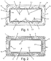
- the frame comprises a rectangular structure (1) having a rectangular central opening (2) with two longitudinal edges (2.1, 2.2) and two transverse edges (2.3, 2.4).
- the four edges (2.1, 2.2, 2.3, 2.4) of the rectangular central opening (2) have first formations (3) for the elastic snap-fitting of electrical apparatus (4).
- the rectangular structure (1) can be made of a plastic material, metallic material, or combinations thereof, and is provided with conventional means for fixing on a mounting receptacle arranged on a wall (not depicted in the drawings), such as slots (5) for fixing the frame to the receptacle by means of screws, for example.
- the rectangular frame additionally comprises at least one pair of two independent cross members (6) which are configured for being arranged transversely between the two longitudinal edges (2.1, 2.2) of the central opening (2) of the rectangular structure (1), as seen in Figures 3 and 4 .
- the cross members (6) have a rectangular shape and each of them comprises two smaller sides (6.1, 6.2) and two larger sides (6.3, 6.4).
- the cross members (6) have fixing means (7) on their smaller sides (6.1, 6.2), which are configured for the elastic snap-fitting of the cross members (6) onto the first formations (3) of the longitudinal edges (2.1, 2.2) of the central opening (2), such that said cross members (6) can optionally be incorporated or removed, depending on the mounting configuration of the electrical apparatus (4) to be established in the frame.
- the cross members (6) have second formations (8) on one of their larger sides (6.3) which are configured for the elastic snap-fitting of electrical apparatus (4). It has been envisaged that the second formations (8) are identical to the first formations (3) of the transverse edges (2.3, 2.4) of the central opening (2).
- the cross members (6) have on the other larger side (6.4) thereof a side flange (9) having a planar edge to prevent interfering with the side flange (9) of the second cross member (6) of the pair placed adjacent to the first cross member (6), according to a first mounting arrangement of the cross members (6) on the frame (see Figure 3 ).
- each cross member (6) has a lower portion with a coupling shape configured for engaging one of the transverse edges (2.3, 2.4) of the central opening (2) when the cross member (6) is arranged at one end of the central opening (2), according to a second mounting arrangement of the cross members (6) on the frame (see Figure 4 ).
- the side flange (9) is not secured on the transverse edge (2.3, 2.4) of the central opening (2), but rather rests on said transverse edge (2.3, 2.4).
- the two cross members (6) of a pair can be arranged in an intermediate position of the central opening (2), dividing said central opening (2) into two independent end openings (2'), as seen in the first mounting arrangement of Figure 3 .
- the cross members (6) are arranged with their side flanges (9) facing one another, such that each end opening (2') has on all its sides formations (3,8) for mounting the electrical apparatus (4), specifically each end opening (2') is bordered by the longitudinal edges (2.1, 2.2) and a transverse edge (2.3, 2.4) of the central opening (2) having the first formations (3) and by the larger side (6.3) of the cross member (6) having the second formations (8).
- the arrangement of the cross members (6) of a pair in an intermediate position of the central opening (2) defines end openings (2') having, for example, standard measurements of 45 mm long by 45 mm wide. Therefore, a square-shaped electrical apparatus (4) having standard measurements of 45 x 45 mm, for example, can be mounted on each of said end openings (2') as shown in Figures 7 and 10 , or two rectangular-shaped electrical apparatus (4) having standard measurements of 45 x 22.5 mm, for example, can also be mounted. In any case, this measurement configuration is non-limiting, and the end openings (2') can have any type of standard measurement required for mounting the electrical apparatus (4).
- the electrical apparatus (4) are usually provided with elastic snap-fitting means (10) on only two opposite side edges, generally on their upper edge and lower edge, such that the electrical apparatus (4) are fixed by the snap-fitting means (10) on the longitudinal edges (2.1, 2.2) of the corresponding end opening (2'), as shown in the section view of Figure 9 .
- Common rectangular frames are usually mounted on the wall of a building in a horizontal position, as shown in Figures 7 and 8 , but when the frame is to be mounted in a vertical arrangement, the electrical apparatus (4) is turned 90° with respect to its horizontal position, since the electrical apparatus (4) only has snap-fitting means (10) on two of its side edges.
- the frame of the invention allows mounting the electrical apparatus (4) in a vertical arrangement without them being turned 90° with respect to the horizontal position thereof, as shown in Figure 10 . Therefore, the electrical apparatus (4) is fixed in its respective end opening (2') when the snap-fitting means (10) thereof are attached to a transverse edge (2.3, 2.4) of the end opening (2') and to the larger side (6.3) of the respective cross member (6).
- the cross members (6) therefore allow, by means of their larger side (6.3) provided with the second formations (8), in combination with the first formations (3) of the edges (2.1, 2.2, 2.3, 2.4) of the central opening (2), effectively securing the electrical apparatus (4) in two alternative positions at 90° in the frame, the frame being able to be installed in a horizontal position, such as in Figures 7 and 8 , or in a vertical position, such as in Figure 10 , the electrical apparatus (4) being kept suitably fixed in their natural position in any of said positions, providing great versatility when using the frame.
- each cross member (6) of a pair are arranged separated from one another, each cross member (6) being arranged in an end position of the central opening (2), such that a smaller central opening (2'') for mounting electrical apparatus (4) is defined between the cross members (6).
- the lower portion of the side flange (9) of each cross member (6) can be coupled to the respective transverse edge (2.3, 2.4) of the central opening (2) on which it is arranged.
- the arrangement of the cross members (6) in end positions of the central opening (2) defines a smaller central opening (2'') having standard measurements of 45 x 90 mm, for example. Therefore, two square-shaped electrical apparatus (4) having standard measurements of 45 x 45 mm, for example, can be mounted on said smaller central opening (2'') as shown in Figure 8 , or four rectangular-shaped electrical apparatus (4) having standard measurements of 45 x 22.5 mm, for example, can also be mounted, these mounting configurations not being limiting in any case.
- the cross members (6) can therefore be located in an intermediate position of the central opening (2) which allows mounting standard electrical apparatus in a vertical or horizontal position, or in end positions of the central opening (2), such that the same cross members (6) can be used as closure elements for closing the resulting gaps of the central opening (2), providing the frame with great versatility in terms of mounting thereof.
- the section view of Figure 6 shows the elastic snap-fitting of one of the cross members (6) onto the longitudinal edges (2.1, 2.2) of the central opening (2).
- the fixing means (7) comprise an upper projection (7.1) and a lower projection (7.2) between which there is defined a U-shaped recess (7.3) which engages one of the first formations (3) of the longitudinal edges (2.1, 2.2) of the central opening (2).
- the electrical apparatus (4) comprise snap-fitting means (10), identical to the fixing means (7), which engage the first formations (3) of the longitudinal edges (2.1, 2.2) of the central opening (2).
- the cross members (6) have projections (11) defined at the ends of the side flange (9), in the transition area between a larger side (6.4) and a smaller side (6.1, 6.2) of the cross member (6).
- the projections (11) are configured for engaging recesses (12) of the longitudinal edges (2.1, 2.2) of the central opening (2).
- the projections (11) have a half dovetail shape reciprocally engaging the recesses (12) of the frame.
- the frame has grooves (13) on the edges (2.1, 2.2, 2.3, 2.4) of the central opening (2) used to prevent interfering with the elastic snap-fitting means of some electrical functions arranged in the frame.
- the cross members (6) also have grooves (13) on the larger side (6.3) where the second formations (8) for fixing the electrical apparatus (4) are placed.
- the frame has on its longitudinal edges (2.1, 2.2) through housings (14) for fixing a decorative cover plate on the frame.
- the frame also has in the corners holes (15) for fixing the frame by means of screws to a flat surface, such as a wall.
- the frame has on its smaller sides latching means (16) for coupling with other frames.
- Figures 1 to 4 and 7 to 10 show a rectangular frame with a pair of two cross members (6); nevertheless this embodiment does not exclude configurations of another type, more than one pair of cross members (6) being able to be arranged in the central opening (2) of the frame depending on the size of the rectangular frame.
- Figure 14 shows a rectangular frame with two pairs of cross members (6) such that the central opening (2) is divided into three independent openings where different electrical apparatus (4) can be arranged.
- the frame can have more than one central opening (2), at least one pair of two cross members (6) being arranged in each central opening (2).
Landscapes
- Engineering & Computer Science (AREA)
- Architecture (AREA)
- Civil Engineering (AREA)
- Structural Engineering (AREA)
- Casings For Electric Apparatus (AREA)
- Details Of Indoor Wiring (AREA)
Applications Claiming Priority (1)
| Application Number | Priority Date | Filing Date | Title |
|---|---|---|---|
| ES201631186A ES2600380B1 (es) | 2016-09-12 | 2016-09-12 | Bastidor para montaje de aparatos eléctricos |
Publications (1)
| Publication Number | Publication Date |
|---|---|
| EP3293842A1 true EP3293842A1 (fr) | 2018-03-14 |
Family
ID=57950798
Family Applications (1)
| Application Number | Title | Priority Date | Filing Date |
|---|---|---|---|
| EP17190656.3A Withdrawn EP3293842A1 (fr) | 2016-09-12 | 2017-09-12 | Cadre de montage d'appareil électrique |
Country Status (2)
| Country | Link |
|---|---|
| EP (1) | EP3293842A1 (fr) |
| ES (1) | ES2600380B1 (fr) |
Cited By (3)
| Publication number | Priority date | Publication date | Assignee | Title |
|---|---|---|---|---|
| WO2024079372A1 (fr) * | 2022-10-11 | 2024-04-18 | Schneider Electric España, S.A. | Système de réglage pour le montage d'une unité modulaire électrique et installation électrique comprenant ledit système |
| EP4362253A1 (fr) * | 2022-10-31 | 2024-05-01 | Schneider Electric Industries Sas | Ensemble de montage de dispositif pour montage vertical et horizontal |
| EP4489240A1 (fr) * | 2023-07-04 | 2025-01-08 | Schneider Electric Industries Sas | Agencement d'installation de dispositif de câblage avec plaque centrale d'adaptateur pour installation modulaire |
Citations (6)
| Publication number | Priority date | Publication date | Assignee | Title |
|---|---|---|---|---|
| US5961345A (en) * | 1998-01-14 | 1999-10-05 | Cabletron Systems, Inc. | Faceplate system |
| ES2205995A1 (es) * | 2001-12-04 | 2004-05-01 | Schneider Electric España, S.A. | Conjunto para mecanismos electricos. |
| US20050176278A1 (en) * | 2003-12-31 | 2005-08-11 | Cheatham James F. | Sliding clip electrical connection box mounting bracket |
| EP1675240A1 (fr) * | 2004-12-23 | 2006-06-28 | Legrand | Support d'appareillage électrique multipostes à montage indexé des socles d'appareillage électrique |
| WO2006117817A1 (fr) * | 2005-04-29 | 2006-11-09 | Bticino S.P.A. | Cadre de support pour l'installation d'une paroi sur un appareil electrique |
| US8072779B1 (en) * | 2009-01-07 | 2011-12-06 | Pass & Seymour, Inc. | Recessed electrical device housing assembly and clip |
Family Cites Families (3)
| Publication number | Priority date | Publication date | Assignee | Title |
|---|---|---|---|---|
| US4135337A (en) * | 1977-09-12 | 1979-01-23 | Medlin Lewis B | Mounting means for electric outlet box |
| FR2858126B1 (fr) * | 2003-07-21 | 2006-02-17 | Legrand Sa | Appareillage electrique comprenant un support et au moins un mecanisme d'appareillage a moyens de montage glissants |
| US8629349B2 (en) * | 2010-07-30 | 2014-01-14 | Hubbell Incorporated | Electrical assembly and adapter for wiring device |
-
2016
- 2016-09-12 ES ES201631186A patent/ES2600380B1/es active Active
-
2017
- 2017-09-12 EP EP17190656.3A patent/EP3293842A1/fr not_active Withdrawn
Patent Citations (6)
| Publication number | Priority date | Publication date | Assignee | Title |
|---|---|---|---|---|
| US5961345A (en) * | 1998-01-14 | 1999-10-05 | Cabletron Systems, Inc. | Faceplate system |
| ES2205995A1 (es) * | 2001-12-04 | 2004-05-01 | Schneider Electric España, S.A. | Conjunto para mecanismos electricos. |
| US20050176278A1 (en) * | 2003-12-31 | 2005-08-11 | Cheatham James F. | Sliding clip electrical connection box mounting bracket |
| EP1675240A1 (fr) * | 2004-12-23 | 2006-06-28 | Legrand | Support d'appareillage électrique multipostes à montage indexé des socles d'appareillage électrique |
| WO2006117817A1 (fr) * | 2005-04-29 | 2006-11-09 | Bticino S.P.A. | Cadre de support pour l'installation d'une paroi sur un appareil electrique |
| US8072779B1 (en) * | 2009-01-07 | 2011-12-06 | Pass & Seymour, Inc. | Recessed electrical device housing assembly and clip |
Cited By (3)
| Publication number | Priority date | Publication date | Assignee | Title |
|---|---|---|---|---|
| WO2024079372A1 (fr) * | 2022-10-11 | 2024-04-18 | Schneider Electric España, S.A. | Système de réglage pour le montage d'une unité modulaire électrique et installation électrique comprenant ledit système |
| EP4362253A1 (fr) * | 2022-10-31 | 2024-05-01 | Schneider Electric Industries Sas | Ensemble de montage de dispositif pour montage vertical et horizontal |
| EP4489240A1 (fr) * | 2023-07-04 | 2025-01-08 | Schneider Electric Industries Sas | Agencement d'installation de dispositif de câblage avec plaque centrale d'adaptateur pour installation modulaire |
Also Published As
| Publication number | Publication date |
|---|---|
| ES2600380B1 (es) | 2017-09-13 |
| ES2600380A1 (es) | 2017-02-08 |
Similar Documents
| Publication | Publication Date | Title |
|---|---|---|
| CN111656632A (zh) | 用于壁装式模块化电气设备的复合盖板 | |
| AU2006242791B2 (en) | Support frame for wall mounting an electrical apparatus | |
| EP3293842A1 (fr) | Cadre de montage d'appareil électrique | |
| WO2013033691A2 (fr) | Dispositifs pour montage d'installations électrique, audio et vidéo à des parois et d'autres surfaces plates | |
| EP1882289B1 (fr) | Cadre support auxiliaire pour au moins une appareil d'installation electrique | |
| US7714237B2 (en) | Electrical apparatus and supporting frame for wall-mounting same | |
| KR101171410B1 (ko) | 전기적인 장치를 벽에 설치하기 위한 지지 프레임 및 이를포함하는 부품 그룹 | |
| RU2754816C2 (ru) | Накладной элемент и накладная пластина для настенных модульных электрических приборов | |
| AU2018306532A1 (en) | Cover plate and group of parts for wall-mounting modular electric apparatuses | |
| RU2485653C2 (ru) | Устройство для монтажа электрического блока в канале для прокладки электрических кабелей или проводов и электрический узел, содержащий электрический блок и такое устройство | |
| HK1112660B (en) | Auxiliary support frame for at least one piece of electrical equipment | |
| US20220109288A1 (en) | Switch cabinet arrangement with a switch cabinet and at least one power strip | |
| HK1113277B (en) | Support frame and group of parts, including such frame/ for wall -mounting an electrical apparatus |
Legal Events
| Date | Code | Title | Description |
|---|---|---|---|
| PUAI | Public reference made under article 153(3) epc to a published international application that has entered the european phase |
Free format text: ORIGINAL CODE: 0009012 |
|
| STAA | Information on the status of an ep patent application or granted ep patent |
Free format text: STATUS: THE APPLICATION HAS BEEN PUBLISHED |
|
| AK | Designated contracting states |
Kind code of ref document: A1 Designated state(s): AL AT BE BG CH CY CZ DE DK EE ES FI FR GB GR HR HU IE IS IT LI LT LU LV MC MK MT NL NO PL PT RO RS SE SI SK SM TR |
|
| AX | Request for extension of the european patent |
Extension state: BA ME |
|
| STAA | Information on the status of an ep patent application or granted ep patent |
Free format text: STATUS: REQUEST FOR EXAMINATION WAS MADE |
|
| 17P | Request for examination filed |
Effective date: 20180913 |
|
| RBV | Designated contracting states (corrected) |
Designated state(s): AL AT BE BG CH CY CZ DE DK EE ES FI FR GB GR HR HU IE IS IT LI LT LU LV MC MK MT NL NO PL PT RO RS SE SI SK SM TR |
|
| STAA | Information on the status of an ep patent application or granted ep patent |
Free format text: STATUS: EXAMINATION IS IN PROGRESS |
|
| 17Q | First examination report despatched |
Effective date: 20191218 |
|
| STAA | Information on the status of an ep patent application or granted ep patent |
Free format text: STATUS: THE APPLICATION IS DEEMED TO BE WITHDRAWN |
|
| 18D | Application deemed to be withdrawn |
Effective date: 20201128 |