EP3293872A2 - Moteur pas à pas - Google Patents
Moteur pas à pas Download PDFInfo
- Publication number
- EP3293872A2 EP3293872A2 EP17190179.6A EP17190179A EP3293872A2 EP 3293872 A2 EP3293872 A2 EP 3293872A2 EP 17190179 A EP17190179 A EP 17190179A EP 3293872 A2 EP3293872 A2 EP 3293872A2
- Authority
- EP
- European Patent Office
- Prior art keywords
- stator
- rotor
- pole
- salient poles
- phase
- Prior art date
- Legal status (The legal status is an assumption and is not a legal conclusion. Google has not performed a legal analysis and makes no representation as to the accuracy of the status listed.)
- Withdrawn
Links
- 238000004804 winding Methods 0.000 claims abstract description 11
- 229910000831 Steel Inorganic materials 0.000 claims description 13
- 239000010959 steel Substances 0.000 claims description 13
- 239000002184 metal Substances 0.000 claims description 12
- 229910052751 metal Inorganic materials 0.000 claims description 12
- 210000000078 claw Anatomy 0.000 description 9
- 230000000694 effects Effects 0.000 description 7
- 229910000976 Electrical steel Inorganic materials 0.000 description 5
- 230000001747 exhibiting effect Effects 0.000 description 5
- 239000000696 magnetic material Substances 0.000 description 5
- 230000007246 mechanism Effects 0.000 description 4
- 230000002093 peripheral effect Effects 0.000 description 3
- 229910001335 Galvanized steel Inorganic materials 0.000 description 2
- XEEYBQQBJWHFJM-UHFFFAOYSA-N Iron Chemical compound [Fe] XEEYBQQBJWHFJM-UHFFFAOYSA-N 0.000 description 2
- 239000008397 galvanized steel Substances 0.000 description 2
- 239000000463 material Substances 0.000 description 2
- 239000007769 metal material Substances 0.000 description 2
- 239000011347 resin Substances 0.000 description 2
- 229920005989 resin Polymers 0.000 description 2
- 239000010935 stainless steel Substances 0.000 description 2
- 229910001220 stainless steel Inorganic materials 0.000 description 2
- 230000009471 action Effects 0.000 description 1
- 230000008859 change Effects 0.000 description 1
- 230000003247 decreasing effect Effects 0.000 description 1
- 230000004907 flux Effects 0.000 description 1
- 230000020169 heat generation Effects 0.000 description 1
- 229910052742 iron Inorganic materials 0.000 description 1
- 238000000034 method Methods 0.000 description 1
- 230000004048 modification Effects 0.000 description 1
- 238000012986 modification Methods 0.000 description 1
Images



Classifications
-
- H—ELECTRICITY
- H02—GENERATION; CONVERSION OR DISTRIBUTION OF ELECTRIC POWER
- H02K—DYNAMO-ELECTRIC MACHINES
- H02K37/00—Motors with rotor rotating step by step and without interrupter or commutator driven by the rotor, e.g. stepping motors
- H02K37/10—Motors with rotor rotating step by step and without interrupter or commutator driven by the rotor, e.g. stepping motors of permanent magnet type
- H02K37/12—Motors with rotor rotating step by step and without interrupter or commutator driven by the rotor, e.g. stepping motors of permanent magnet type with stationary armatures and rotating magnets
- H02K37/14—Motors with rotor rotating step by step and without interrupter or commutator driven by the rotor, e.g. stepping motors of permanent magnet type with stationary armatures and rotating magnets with magnets rotating within the armatures
-
- H—ELECTRICITY
- H02—GENERATION; CONVERSION OR DISTRIBUTION OF ELECTRIC POWER
- H02K—DYNAMO-ELECTRIC MACHINES
- H02K1/00—Details of the magnetic circuit
- H02K1/06—Details of the magnetic circuit characterised by the shape, form or construction
- H02K1/12—Stationary parts of the magnetic circuit
- H02K1/14—Stator cores with salient poles
- H02K1/146—Stator cores with salient poles consisting of a generally annular yoke with salient poles
-
- H—ELECTRICITY
- H02—GENERATION; CONVERSION OR DISTRIBUTION OF ELECTRIC POWER
- H02K—DYNAMO-ELECTRIC MACHINES
- H02K1/00—Details of the magnetic circuit
- H02K1/06—Details of the magnetic circuit characterised by the shape, form or construction
- H02K1/12—Stationary parts of the magnetic circuit
- H02K1/16—Stator cores with slots for windings
- H02K1/165—Shape, form or location of the slots
-
- H—ELECTRICITY
- H02—GENERATION; CONVERSION OR DISTRIBUTION OF ELECTRIC POWER
- H02K—DYNAMO-ELECTRIC MACHINES
- H02K1/00—Details of the magnetic circuit
- H02K1/06—Details of the magnetic circuit characterised by the shape, form or construction
- H02K1/22—Rotating parts of the magnetic circuit
- H02K1/27—Rotor cores with permanent magnets
- H02K1/2706—Inner rotors
- H02K1/272—Inner rotors the magnetisation axis of the magnets being perpendicular to the rotor axis
- H02K1/2726—Inner rotors the magnetisation axis of the magnets being perpendicular to the rotor axis the rotor consisting of a single magnet or two or more axially juxtaposed single magnets
-
- H—ELECTRICITY
- H02—GENERATION; CONVERSION OR DISTRIBUTION OF ELECTRIC POWER
- H02K—DYNAMO-ELECTRIC MACHINES
- H02K1/00—Details of the magnetic circuit
- H02K1/06—Details of the magnetic circuit characterised by the shape, form or construction
- H02K1/22—Rotating parts of the magnetic circuit
- H02K1/27—Rotor cores with permanent magnets
- H02K1/2706—Inner rotors
- H02K1/272—Inner rotors the magnetisation axis of the magnets being perpendicular to the rotor axis
- H02K1/274—Inner rotors the magnetisation axis of the magnets being perpendicular to the rotor axis the rotor consisting of two or more circumferentially positioned magnets
- H02K1/2753—Inner rotors the magnetisation axis of the magnets being perpendicular to the rotor axis the rotor consisting of two or more circumferentially positioned magnets the rotor consisting of magnets or groups of magnets arranged with alternating polarity
-
- H—ELECTRICITY
- H02—GENERATION; CONVERSION OR DISTRIBUTION OF ELECTRIC POWER
- H02K—DYNAMO-ELECTRIC MACHINES
- H02K3/00—Details of windings
- H02K3/04—Windings characterised by the conductor shape, form or construction, e.g. with bar conductors
- H02K3/12—Windings characterised by the conductor shape, form or construction, e.g. with bar conductors arranged in slots
-
- H—ELECTRICITY
- H02—GENERATION; CONVERSION OR DISTRIBUTION OF ELECTRIC POWER
- H02K—DYNAMO-ELECTRIC MACHINES
- H02K3/00—Details of windings
- H02K3/04—Windings characterised by the conductor shape, form or construction, e.g. with bar conductors
- H02K3/28—Layout of windings or of connections between windings
-
- H—ELECTRICITY
- H02—GENERATION; CONVERSION OR DISTRIBUTION OF ELECTRIC POWER
- H02K—DYNAMO-ELECTRIC MACHINES
- H02K5/00—Casings; Enclosures; Supports
- H02K5/04—Casings or enclosures characterised by the shape, form or construction thereof
-
- H—ELECTRICITY
- H02—GENERATION; CONVERSION OR DISTRIBUTION OF ELECTRIC POWER
- H02K—DYNAMO-ELECTRIC MACHINES
- H02K5/00—Casings; Enclosures; Supports
- H02K5/04—Casings or enclosures characterised by the shape, form or construction thereof
- H02K5/16—Means for supporting bearings, e.g. insulating supports or means for fitting bearings in the bearing-shields
- H02K5/161—Means for supporting bearings, e.g. insulating supports or means for fitting bearings in the bearing-shields radially supporting the rotary shaft at both ends of the rotor
-
- H—ELECTRICITY
- H02—GENERATION; CONVERSION OR DISTRIBUTION OF ELECTRIC POWER
- H02K—DYNAMO-ELECTRIC MACHINES
- H02K2213/00—Specific aspects, not otherwise provided for and not covered by codes H02K2201/00 - H02K2211/00
- H02K2213/03—Machines characterised by numerical values, ranges, mathematical expressions or similar information
Definitions
- the present invention relates to a stepping motor, and more particularly, to a stepping motor being used as the driving source of a paper feeding mechanism in a laser printer, a copier, etc.
- a laser printer, a copier, etc. are each equipped with a paper feeding mechanism to feed sheets of paper one by one at a predetermined speed (pitch).
- a driving source of such a paper feeding mechanism a driving source that uses a stepping motor is known.
- variable reluctance (VR) type a permanent magnet (PM) type
- HB hybrid
- the present invention relates to a permanent magnet (PM) type stepping motor.
- a claw-pole type two-phase PM stepping motor is known as a PM stepping motor (for example, refer to Patent Document 1).
- a claw-pole type two-phase PM stepping motor having a step angle of 7.5° (hereafter referred to as "the two-phase PM stepping motor according to the related art") will be described below.
- the two-phase PM stepping motor according to the related art is equipped with a rotor and a stator surrounding the circumference of the rotor.
- the rotor is magnetized by S-poles and N-poles alternately arranged on a straight line parallel to the rotation shaft thereof.
- the rotor is composed of a permanent magnet (rotor magnet) magnetized at 24 poles in the circumferential direction and a rotation shaft installed at the center of this rotor magnet.
- the stator is formed of a combination of two sets, each set being composed of a ring-shaped coil and teeth formed by sheet metal processing.
- the claw-shaped portions of an iron plate are referred to as claw poles or inductors.
- the claws between which the coil is interposed are combined so as to be engaged with each other in the vertical direction.
- each set has a structure in which two yokes (stator yokes), each yoke being provided with the claw poles disposed at every 30°, are combined so that the claw poles are alternately disposed at every 15°, and the ring-shaped coil is disposed around the outer periphery of the claw poles.
- the stator is composed of an A-phase stator and a B-phase stator arranged in the axial direction (the thrust direction).
- the magnetic pole of the magnetic field generated at the claw pole is switched by switching the direction of the current to be supplied to the ring-shaped coil of each of the two phases.
- the magnetic pole of the permanent magnet (the rotor magnet) is attracted depending on the generated magnetic pole, whereby the rotor carries out step rotation (intermittent rotation) at a resolution of 7.5°.
- an inner rotor motor is also known as a prior art relating to the present invention, although the motor is not a stepping motor (for example, refer to Patent Document 2).
- This inner rotor motor is equipped with a rotor and a stator disposed outside this rotor.
- the rotor is equipped with a sleeve secured to its shaft and a rotor magnet secured to the outer periphery of this sleeve.
- the rotor magnet is magnetized at four poles so that the polarities of the poles are inverted in a sequence of N, S, N and S in the circumferential direction.
- the stator is equipped with stator yokes provided with a plurality of salient poles having pole teeth opposed to the rotor and a stator coil wound around the plurality of salient poles.
- the stator yoke has a structure in which a plurality of punched steel sheets is stacked in the axial direction.
- the stator yoke is equipped with a back yoke having a nearly annular shape and six salient poles protruding inward from this back yoke, and pole teeth are provided at the tip ends of the respective salient poles.
- the stator coil is wound around the six salient poles in a sequence of winding directions: clockwise, counterclockwise, and clockwise.
- An object of the present invention is to provide a two-phase PM stepping motor exhibiting an excellent noise-reducing effect.
- Another object of the present invention is to provide a two-phase PM stepping motor capable of generating large torque.
- Another object of the present invention is to provide a two-phase PM stepping motor exhibiting an excellent heat radiating effect.
- a stepping motor which is two-phase PM type, including:
- the stepping motor may be configured such that: a step angle of the two-phase PM stepping motor is 7.5°, the number of the poles of the rotor is equal to 24, and the number of the salient poles of the stator yoke is equal to 16.
- the stator yoke may have a structure in which a plurality of metal sheets are stacked in an axial direction of the rotor.
- the metal sheets may be punched steel sheets.
- the stepping motor may further include a case covering the stator so as to contact with an outer circumferential face of the stator yoke.
- the stepping motor may be configured such that: the stator yoke includes a back yoke having an annular shape, the salient poles protrude from the back yoke inward in a radial direction of the rotor, and the pole teeth are provided at tip ends of the respective salient poles.
- the case may contact with an outer circumferential face of the back yoke of the stator yoke.
- the first-phase stator coils may be electrically conducted to each other, and the second-phase stator coils may be electrically conducted to each other.
- a stepping motor including:
- the metal sheets may be punched steel sheets.
- a stepping motor including:
- the stepping motor disclosed in Patent Document 1 has the two-phase structure in which the A-phase stator and the B-phase stator are stacked in two stages in the thrust direction. Furthermore, as described above, since the rotor is rotated by the switching of the A-phase and the B-phase, vibration (noise) in the thrust direction occurs due to the difference between the magnetic field strength values of the two phases.
- the stepping motor disclosed in Patent Document 1 is further equipped with the case for covering the stator.
- the stator has a structure in which the ring-shaped coils are wound around the stator yokes, the area of the case making direct contact with the stator yokes is small. Hence, the heat generated in the stepping motor cannot be radiated to the outside efficiently.
- the inner rotor motor disclosed in Patent Document 2 is not a stepping motor and cannot carry out stepping operation.
- an object of the present invention is to provide a two-phase PM stepping motor exhibiting an excellent noise-reducing effect.
- Another object of the present invention is to provide a two-phase PM stepping motor capable of generating large torque.
- Still another object of the present invention is to provide a two-phase PM stepping motor exhibiting an excellent heat radiating effect.
- the related art of the present invention will first be described referring to the accompanying drawings for easy understanding of the present invention.
- the related art described below is substantially identical to the stepping motor (the claw-pole type two-phase PM stepping motor) disclosed in Patent Document 1 described above.
- the related art is not completely identical to the stepping motor disclosed in Patent Document 1, but is described in more detail with some minor revisions.
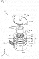
- Figs. 1 and 2 are views showing a two-phase PM stepping motor 10 according to the related art.
- Fig. 1 is an exploded perspective view showing the two-phase PM stepping motor 10
- Fig. 2 is a vertical sectional view showing the two-phase PM stepping motor 10.
- Such an orthogonal coordinate system (X, Y, Z) as shown in Figs. 1 and 2 is herein used.
- the Z-direction is the up-down direction (the height direction; the axial direction) in which the rotation axis MA of the motor 10 extends
- the X-direction is the front-rear direction (the depth direction) orthogonal to the direction (the Z-direction) of the rotation axis MA of the motor 10
- the Y-direction is the left-right direction (the width direction) orthogonal to both the Z-direction and the X-direction.
- the two-phase PM stepping motor 10 shown in the figures has a shape being substantially rotationally symmetrical with respect to the rotation axis MA of the motor 10.
- the step angle of the two-phase PM stepping motor 10 is 7.5°.
- the two-phase PM stepping motor 10 is equipped with a case 20, a bracket 30, a stator 40 and a rotor 50.
- the case 20 has a hollow cylindrical shape being open at one end (the upper end).
- the bracket 30 closes the open end (the upper end) of the case 20.
- the stator 40 is provided along the inner peripheral face of the case 20.
- the rotor 50 is rotatably supported by first and second bearing sections 20a and 30a respectively provided on the case 20 and the bracket 30.
- the case 20 is made of a metal material and is equipped with the first bearing section 20a near the center of the closed end face (the lower end face) thereof.
- the bracket 30 is made of a metal material and is equipped with the second bearing section 30a near the center thereof.
- the stator 40 is composed of a cylindrical yoke unit 42 and first and second stator coils 46 and 47, these being accommodated inside the case 20.
- the yoke unit 42 is equipped with first to fourth stator yokes 421, 422, 423 and 424 provided with ring-shaped flange sections having an outside diameter nearly equal to the inside diameter of the case 20.
- the first to fourth stator yokes 421, 422, 423 and 424 of the yoke unit 42 are integrally molded with a bobbin 425 made of resin.
- the first stator coil 46 is wound around the first winding section demarcated by the first and second stator yokes 421 and 422.
- the second stator coil 47 is wound around the second winding section demarcated by the third and fourth stator yokes 423 and 424. After the first and second stator coils 46 and 47 are wound, the stator 40 is accommodated inside the case 20 and secured thereto.
- the first and second stator coils 46 and 47 are not shown in Fig. 2 . Furthermore, the numerals 60 and 65 in Figs. 1 and 2 respectively designate a circuit board and connectors for supplying current to the first and second stator coils 46 and 47.
- stator 40 is composed of the A-phase stator (421; 422; 46) and the B-phase stator (423; 424; 47) arranged in the axial direction (the thrust direction).
- the rotor 50 is composed of a rotation shaft 52 and a rotor magnet 54 having a hollow cylindrical shape.
- the rotation shaft 52 is rotatably supported by the first and second bearing sections 20a and 30a.
- the rotor magnet 54 is secured to the rotation shaft 52.
- the outside diameter of the rotor magnet 54 is formed so as to be slightly smaller than the inside diameter of the center hole of the yoke unit 42.
- the rotor magnet 54 is magnetized along the circumferential direction thereof. In this example, the rotor magnet 54 is magnetized by S-poles and N-poles alternately arranged on a straight line parallel to the rotation shaft 52, thereby being magnetized at 24 poles in the circumferential direction.
- the first stator yoke 421 is made of a magnetic material.
- the first stator yoke 421 is composed of a ring-shaped flange section 421 a and a plurality of comb-teeth-like salient pole sections 421 b provided so as to rise in the vertical direction from the inner peripheral section of the ring-shaped flange section 421 a.
- the first stator yoke 421 has 12 comb-teeth-like salient pole sections 421b disposed at every 30°.
- Each salient pole section of the comb-teeth-like salient pole sections 421 b is also referred to as a claw pole or an inductor.
- the first to fourth stator yokes 421 to 424 are mutually combined so that the second stator yoke 422 and the third stator yoke 423 are mutually placed back to back and so that the phase of the comb-teeth-like salient pole sections of one pair of stator yokes (421 and 422) is shifted by a predetermined value with respect to the phase of the comb-teeth-like salient pole sections of the other pair of stator yokes (423 and 424), the first to fourth stator yokes 421 to 424 are accommodated in a metal mold for forming the bobbin 425, and the bobbin 425 made of resin is molded around the first to fourth stator yokes 421 to 424. Consequently, the yoke unit 42 is completed.
- the above-mentioned predetermined value is 7.5°.
- the magnetic fields generated in the first and second stator coils 46 and 47 interact with the magnetic field of the rotor magnet 54 via the stator yokes 421, 422, 423 and 424 of the yoke unit 42 by supplying drive current to the first and second stator coils 46 and 47 of the stator 40.
- the rotor 50 is intermittently (at a resolution of 7.5° in this example) rotated (rotated in steps) by the action of the comb-teeth-like salient pole sections of the respective stator yokes 421 to 424.
- the two-phase PM stepping motor 10 has the two-phase structure in which the A-phase stator (421; 422; 46) and the B-phase stator (423; 424; 47) are stacked in two stages in the thrust direction (the axial direction) Z. Furthermore, since the rotor 50 is rotated by the switching of the A-phase and the B-phase as described above in the two-phase PM stepping motor 10 according to the related art, vibration (noise) in the thrust direction (the axial direction) occurs due to the difference between the magnetic field strength values of the two phases.
- metal sheets are frequently used as the magnetic materials for the first to fourth stator yokes 421 to 424.
- the metal sheets may be specifically galvanized steel sheets, silicon steel sheets and stainless steel sheets.
- the magnetic field generated by such a magnetic material depends on the performance of the selected material and the area and thickness of the claw pole.
- magnetic saturation occurs eventually in the first to fourth stator yokes 421 to 424.
- the torque to be generated by the two-phase PM stepping motor 10 according to the related art is restricted and cannot be increased further.
- the two-phase PM stepping motor 10 is further equipped with the case 20 for covering the stator 40.
- the stator 40 has a structure in which the ring-shaped first and second stator coils 46 and 47 are wound around the first to fourth stator yokes 421 to 424, the area of the case 20 making direct contact with the first to fourth stator yokes 421 to 424 is small. Hence, the heat generated in the stepping motor 10 cannot be radiated to the outside efficiently.
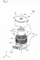
- Fig. 3 is an exploded perspective view showing the two-phase PM stepping motor 10A
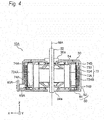
- Fig. 4 is a vertical sectional view showing the two-phase PM stepping motor 10A.
- Such an orthogonal coordinate system (X, Y, Z) as shown in Figs. 3 and 4 is herein used.
- the Z-direction is the up-down direction (the vertical direction) in which the rotation axis MA of the motor 10A extends
- the X-direction is the front-rear direction (the depth direction) orthogonal to the direction (the Z-direction) of the rotation axis MA of the motor 10A
- the Y-direction is the left-right direction (the width direction) orthogonal to both the Z-direction and the X-direction.
- the two-phase PM stepping motor 10A shown in the figures has a shape being substantially rotationally symmetrical with respect to the rotation axis MA of the motor 10A.
- the step angle of the two-phase PM stepping motor 10A is 7.5°.
- the two-phase PM stepping motor 10A shown in the figures has a configuration substantially similar to that of the two-phase PM stepping motor 10 according to the related art described above except that the structures (configurations) of the stator and the case are different as described later, thereby operates similarly.
- the stator is designated by the reference numeral 70
- the case is designated by the reference numeral 80.
- the components having the same functions as those of the components of the two-phase PM stepping motor 10 shown in Figs. 1 and 2 are designated by the same reference numerals. In the following description, only the differences from the two-phase PM stepping motor 10 according to the related art will be described in detail to simplify the explanation.
- the two-phase PM stepping motor 10A is equipped with a case 80, a bracket 30, a stator 70 and a rotor 50.
- the case 80 is composed of an upper case 82 and a lower case 84.
- the upper case 82 has a hollow cylindrical shape being open at one end (the lower end).
- the lower case 84 closes the open end (the lower end) of the upper case 82.
- the bracket 30 is provided at the upper end of the upper case 82.
- the stator 70 is provided along the inner peripheral face of the upper case 82.
- the rotor 50 is rotatably supported by first and second bearing sections 84a and 30a respectively provided on the lower case 84 and the bracket 30.
- the stator 70 is composed of a stator yoke 72 and a stator coil 74, these being accommodated inside the case 80.
- the stator yoke 72 is also referred to as a stator core.
- the stator yoke 72 is provided with 16 salient poles 724 disposed at intervals of an equal angle (22.5° in the example shown in the figures) in the circumferential direction and having pole teeth 726 opposed to the rotor 50.
- the stator coil 74 is wound around the 16 salient poles 724 as described later.
- the stator yoke 72 has a structure in which a plurality of punched steel sheets, such as silicon steel sheets, is stacked in the axial direction Z.
- 41 silicon steel sheets, each having a thickness of 0.5 mm, are stacked in the axial direction Z to form the stator yoke 72.
- the stator yoke 72 is equipped with a back yoke 722 having a nearly annular shape and the 16 salient poles 724 protruding inward from this back yoke 722.
- Pole teeth 726 are provided at the tip ends of the respective salient poles 724.
- the pole teeth 726 being open in an umbrella shape are opposed to the rotor magnet 54 with a clearance provided therebetween.
- the stator coil 74 is wound around the respective salient poles 724.
- the numerals 60A and 65A in Figs. 3 and 4 respectively designate a circuit board and a connector for supplying current to the stator coil 74.
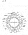
- Fig. 5 is a cross-sectional view showing the arrangement relationship between the rotor 50 (the rotor magnet 54) and the stator 70 of the two-phase PM stepping motor 10A, with the stator coil not shown.
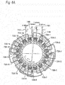
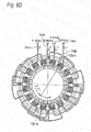
- Figs. 6A , 6B , 6C and 6D are views for explaining the operation of the two-phase PM stepping motor 10A.
- Each of these figures is a schematic cross-sectional view indicating a state in which the rotor 50 is rotated with respect to the stator 70 by a step angle of 7.5°.
- stator 70 will be described in more detail referring to Figs. 5 and 6A .
- the stator coil 74 is composed of a first-phase stator coil 74A and a second-phase stator coil 74B.
- the first phase is also referred to as an A-phase and the second phase is also referred to as a B-phase.
- the first-phase stator coil 74A is also referred to as an A-phase stator coil and the second-phase stator coil 74B is also referred to as a B-phase stator coil.
- the 16 salient poles 724 of the stator yoke 72 are alternately selected in the circumferential direction and thereby divided into a first group of eight salient poles 724A and a second group of eight salient poles 724B.
- Each of the first group of eight salient poles 724A is referred to as an A-phase salient pole and each of the second group of eight salient poles 724B is referred to as a B-phase salient pole.
- the first-phase stator coil 74A is disposed in a ring shape along the outer periphery of the first group of eight salient poles (A-phase salient poles) 724A while the winding direction on the salient poles is changed for each pole in the circumferential direction.
- the second-phase stator coil 74B is disposed in a ring shape along the outer periphery of the second group of eight salient poles (B-phase salient poles) 724B while the winding direction on the salient poles is changed for each pole in the circumferential direction.
- stator coil 74 The method for winding the stator coil 74 around the 16 salient poles 724 of the stator yoke 72 will be described below more specifically.
- the 16 salient poles 724 are referred to as a first salient pole 724-1, a second salient pole 724-2, ..., and a 16th salient pole 724-16 clockwise with reference to the 12 o'clock direction (the upper direction).
- the 16 pole teeth 726 are referred to as a first pole tooth 726-1, a second pole tooth 726-2, ..., and a 16th pole tooth 726-16 clockwise with reference to the 12 o'clock direction (the upper direction).
- the first group of eight salient poles (A-phase salient poles) 724A is composed of odd-numbered salient poles, that is, the first salient pole 724-1, the third salient pole 724-3, the fifth salient pole 724-5, the seventh salient pole 724-7, the ninth salient pole 724-9, the 11th salient pole 724-11, the 13th salient pole 724-13, and the 15th salient pole 724-15.
- the second group of eight salient poles (B-phase salient poles) 724B is composed of even-numbered salient poles, that is, the second salient pole 724-2, the fourth salient pole 724-4, the sixth salient pole 724-6, the eighth salient pole 724-8, the 10th salient pole 724-10, the 12th salient pole 724-12, the 14th salient pole 724-14, and the 16th salient pole 724-16.
- the first-phase stator coil 74A is wound around the first salient pole 724-1 clockwise, wound around the third salient pole 724-3 counterclockwise, wound around the fifth salient pole 724-5 clockwise, wound around the seventh salient pole 724-7 counterclockwise, wound around the ninth salient pole 724-9 clockwise, wound around the 11th salient pole 724-11 counterclockwise, wound around the 13th salient pole 724-13 clockwise, and wound around the 15th salient pole 724-15 counterclockwise.
- the second-phase stator coil 74B is wound around the second salient pole 724-2 clockwise, wound around the fourth salient pole 724-4 counterclockwise, wound around the sixth salient pole 724-6 clockwise, wound around the eighth salient pole 724-8 counterclockwise, wound around the 10th salient pole 724-10 clockwise, wound around the 12th salient pole 724-12 counterclockwise, wound around the 14th salient pole 724-14 clockwise, and wound around the 16th salient pole 724-16 counterclockwise.
- a forward current is supplied to the first-phase stator coil 74Aand a forward current is also supplied to the second-phase stator coil 74B as shown in Fig. 6A .
- a forward current is supplied to the first-phase stator coil 74A and a forward current is also supplied to the second-phase stator coil 74B as shown in Fig. 6A .
- Fig. 6A As shown in Fig.
- the first pole tooth 726-1 becomes an N-pole
- the second pole tooth 726-2 becomes an N-pole
- the third pole tooth 726-3 becomes an S-pole
- the fourth pole tooth 726-4 becomes an S-pole
- the fifth pole tooth 726-5 becomes an N-pole
- the sixth pole tooth 726-6 becomes an N-pole
- the seventh pole tooth 726-7 becomes an S-pole
- the eighth pole tooth 726-8 becomes an S-pole
- the ninth pole tooth 726-9 becomes an N-pole
- the 10th pole tooth 726-10 becomes an N-pole
- the 11th pole tooth 726-11 becomes an S-pole
- the 12th pole tooth 726-12 becomes an S-pole
- the 13th pole tooth 726-13 becomes an N-pole
- the 14th pole tooth 726-14 becomes an N-pole
- the 15th pole tooth 726-15 becomes an S-pole
- the 16th pole tooth 726-16 becomes an S-pole.
- the rotor magnet 54 of the rotor 50 is magnetized at 24 poles in the circumferential direction as shown in Fig. 6D so as to be magnetized alternately to an S-pole, an N-pole, an S-pole, an N-pole, ... clockwise with reference to the 12 o'clock direction (the upper direction).
- the rotor magnet 54 is magnetized to an S-pole in the 12 o'clock direction (the upper direction), the 3 o'clock direction (the right direction), the 6 o'clock direction (the lower direction), and the 9 o'clock direction (the left direction).
- a forward current is supplied to the first-phase stator coil 74A and a forward current is also supplied to the second-phase stator coil 74B as shown in Fig. 6A .
- the first pole tooth 726-1 becomes an N-pole
- the second pole tooth 726-2 becomes an N-pole
- the third pole tooth 726-3 becomes an S-pole
- the fourth pole tooth 726-4 becomes an S-pole
- the fifth pole tooth 726-5 becomes an N-pole
- the sixth pole tooth 726-6 becomes an N-pole
- the seventh pole tooth 726-7 becomes an S-pole
- the eighth pole tooth 726-8 becomes an S-pole
- the ninth pole tooth 726-9 becomes an N-pole
- the 10th pole tooth 726-10 becomes an N-pole
- the 11th pole tooth 726-11 becomes an S-pole
- the 12th pole tooth 726-12 becomes an S-pole
- the 13th pole tooth 726-13 becomes an N-pole
- the 14th pole tooth 726-14 becomes an N-pole
- the 15th pole tooth 726-15 becomes
- a forward current is supplied to the first-phase stator coil 74A and a backward current is supplied to the second-phase stator coil 74B as shown in Fig. 6B .
- the first pole tooth 726-1 becomes an N-pole
- the second pole tooth 726-2 becomes an S-pole
- the third pole tooth 726-3 becomes an S-pole
- the fourth pole tooth 726-4 becomes an N-pole
- the fifth pole tooth 726-5 becomes an N-pole
- the sixth pole tooth 726-6 becomes an S-pole
- the seventh pole tooth 726-7 becomes an S-pole
- the eighth pole tooth 726-8 becomes an N-pole
- the ninth pole tooth 726-9 becomes an N-pole
- the 10th pole tooth 726-10 becomes an S-pole
- the 11 th pole tooth 726-11 becomes an S-pole
- the 12th pole tooth 726-12 becomes an N-pole
- the 13th pole tooth 726-13 becomes an N-pole
- the 14th pole tooth 726-14 becomes an S-pole
- the 15th pole tooth 726-15
- the rotor 50 is rotated by 7.5° clockwise around the rotation axis MA and stopped. Hence, the rotor 50 is rotated by 15° clockwise around the rotation axis MA from the initial state.
- a backward current is supplied to the first-phase stator coil 74A and a backward current is supplied to the second-phase stator coil 74B as shown in Fig. 6C .
- the first pole tooth 726-1 becomes an S-pole
- the second pole tooth 726-2 becomes an S-pole
- the third pole tooth 726-3 becomes an N-pole
- the fourth pole tooth 726-4 becomes an N-pole
- the fifth pole tooth 726-5 becomes an S-pole
- the sixth pole tooth 726-6 becomes an S-pole
- the seventh pole tooth 726-7 becomes an N-pole
- the eighth pole tooth 726-8 becomes an N-pole
- the ninth pole tooth 726-9 becomes an S-pole
- the 10th pole tooth 726-10 becomes an S-pole
- the 11th pole tooth 726-11 becomes an N-pole
- the 12th pole tooth 726-12 becomes an N-pole
- the 13th pole tooth 726-13 becomes an S-pole
- the 14th pole tooth 726-14 becomes an S-pole
- the rotor 50 is rotated by 7.5° clockwise around the rotation axis MA and stopped.
- the rotor 50 is rotated by 22.5° clockwise around the rotation axis MA from the initial state.
- a backward current is supplied to the first-phase stator coil 74A and a forward current is supplied to the second-phase stator coil 74B as shown in Fig. 6D .
- the first pole tooth 726-1 becomes an S-pole
- the second pole tooth 726-2 becomes an N-pole
- the third pole tooth 726-3 becomes an N-pole
- the fourth pole tooth 726-4 becomes an S-pole
- the fifth pole tooth 726-5 becomes an S-pole
- the sixth pole tooth 726-6 becomes an N-pole
- the seventh pole tooth 726-7 becomes an N-pole
- the eighth pole tooth 726-8 becomes an S-pole
- the ninth pole tooth 726-9 becomes an S-pole
- the 10th pole tooth 726-10 becomes an N-pole
- the 11th pole tooth 726-11 becomes an N-pole
- the 12th pole tooth 726-12 becomes an S-pole
- the 13th pole tooth 726-13 becomes an S-pole
- the 14th pole tooth 726-14 becomes an N-pole
- the 15th pole tooth 726-15 becomes
- the rotor 50 is rotated by 7.5° clockwise around the rotation axis MA and stopped. Hence, the rotor 50 is rotated by 30° clockwise around the rotation axis MA from the initial state.
- the state of the rotor 50 at this time is the same as the above-mentioned initial state.
- stator yoke (stator core) 72 of the stator 70 has the 16 salient poles 724 in the circumferential direction thereof, whereby magnetic pole switching is not carried out in the thrust direction. Consequently, a noise-reducing effect can be expected.
- the stator yoke (stator core) 72 of the stator 70 has a structure in which a plurality of steel sheets is stacked. Hence, the total magnetic flux can be increased, and the limit of magnetic saturation can be raised. As a result, the torque generated by the two-phase PM stepping motor 10A can be made larger than that of the two-phase PM stepping motor 10 according to the related art, whereby the motor efficiency of the motor 10A can be improved.
- the upper case 82 of the case 80 makes direct contact with the back yoke 722 of the stator yoke (stator core) 72 of the stator 70, whereby the area of the contact can be increased.
- the motor 10A has a high heat radiating effect, and heat generation of the motor 10Acan be suppressed.
- the motor having a configuration in which the step angle is 7.5°, the rotor magnet 54 of the rotor 50 is magnetized at 24 poles, and the stator yoke 72 of the stator 70 has the 16 salient poles 724 is taken as an example and described.
- the present invention is not limited to the motor configured as described above as a matter of course.
- the step angle is not limited to 7.5°, but may be changed to other angles, such as 15° and 3.25°.
- the number of the poles of the rotor magnet and the number of the salient poles of the stator yoke can be changed depending on the change in the step angle.
- the present invention can be applied to a two-phase PM stepping motor in which the rotor magnet is magnetized at P pieces of poles, P being equal to a multiple of 6, and the stator yoke has M pieces of salient poles, M being equal to a multiple of 8.
- stator yoke stator core formed by stacking 41 silicon steel sheets, each having a thickness of 0.5 mm
- the number of steel sheets to be stacked and the thickness of the steel sheet may be changed depending on the specifications of a motor.
- the number of steel sheets to be stacked may merely be reduced without changing the thickness.
- the torque of a motor is desired to be improved, the number of steel sheets to be stacked may merely be increased without changing the thickness.
- the thickness of the steel sheet is not limited to 0.5 mm, but steel sheets having various thickness values, such as 0.65 mm, may be used as a matter of course.
- the step angle can be changed to other step angles by increasing or decreasing the number of the salient poles of the stator yoke using a multiple of 8 as described above.
- the stepping motor according to the present invention is not used only as the drive source of a paper feeding mechanism, but can be used generally for apparatuses that are required to be rotated intermittently at a predetermined pitch.
- the present invention can provide a two-phase PM stepping motor exhibiting an excellent noise-reducing effect.
Landscapes
- Engineering & Computer Science (AREA)
- Power Engineering (AREA)
- Iron Core Of Rotating Electric Machines (AREA)
- Permanent Magnet Type Synchronous Machine (AREA)
- Windings For Motors And Generators (AREA)
- Control Of Stepping Motors (AREA)
Applications Claiming Priority (1)
| Application Number | Priority Date | Filing Date | Title |
|---|---|---|---|
| JP2016175371A JP2018042385A (ja) | 2016-09-08 | 2016-09-08 | ステッピングモータ |
Publications (2)
| Publication Number | Publication Date |
|---|---|
| EP3293872A2 true EP3293872A2 (fr) | 2018-03-14 |
| EP3293872A3 EP3293872A3 (fr) | 2018-03-28 |
Family
ID=59829298
Family Applications (1)
| Application Number | Title | Priority Date | Filing Date |
|---|---|---|---|
| EP17190179.6A Withdrawn EP3293872A3 (fr) | 2016-09-08 | 2017-09-08 | Moteur pas à pas |
Country Status (4)
| Country | Link |
|---|---|
| US (1) | US20180069462A1 (fr) |
| EP (1) | EP3293872A3 (fr) |
| JP (1) | JP2018042385A (fr) |
| CN (1) | CN107809158A (fr) |
Families Citing this family (6)
| Publication number | Priority date | Publication date | Assignee | Title |
|---|---|---|---|---|
| CN112421928B (zh) * | 2019-08-20 | 2025-09-05 | 上海鸣志电器股份有限公司 | 一种7.5°步距角步进电机 |
| CN112421927B (zh) * | 2019-08-20 | 2025-09-12 | 上海鸣志电器股份有限公司 | 一种18°步距角步进电机 |
| KR102756282B1 (ko) * | 2020-04-14 | 2025-01-20 | 에이치엘만도 주식회사 | 조향 보조 장치 |
| FR3111326B1 (fr) * | 2020-06-16 | 2022-07-08 | Safran Helicopter Engines | Ensemble propulsif a helice a pales repliable et procede d'arret de l'helice dans une position angulaire indexee |
| US11742736B2 (en) | 2020-10-09 | 2023-08-29 | Lin Engineering, Inc. | Step motor with spacing of same-phase stator pole groups based on one-half rotor tooth pitch |
| CN118646236A (zh) * | 2024-05-28 | 2024-09-13 | 宁波精华电子科技股份有限公司 | 一种步进调光电机结构 |
Citations (2)
| Publication number | Priority date | Publication date | Assignee | Title |
|---|---|---|---|---|
| JP3289687B2 (ja) | 1998-09-30 | 2002-06-10 | ミツミ電機株式会社 | ステッピングモータ |
| JP5580159B2 (ja) | 2010-09-30 | 2014-08-27 | ミネベア株式会社 | インナーロータ型モータ |
Family Cites Families (9)
| Publication number | Priority date | Publication date | Assignee | Title |
|---|---|---|---|---|
| US5444316A (en) * | 1992-07-31 | 1995-08-22 | Ishikawajima Harima Heavy Industries Co., Ltd. | Hybrid stepping motor, driving method for the same and coil winding method for the same |
| TWI296875B (en) * | 2002-04-25 | 2008-05-11 | Step motor with multiple stators | |
| US6969930B2 (en) * | 2004-04-29 | 2005-11-29 | Lin Ted T | Half-stepping motor with bifilar winding ratio for smooth motion |
| CN100517925C (zh) * | 2006-03-31 | 2009-07-22 | 厦门达真电机有限公司 | 一种永磁式爪型步进电机的定子结构 |
| JP5656436B2 (ja) * | 2010-03-31 | 2015-01-21 | 国産電機株式会社 | 固定子コイル、回転電機および自動車 |
| EP2978105A1 (fr) * | 2014-07-22 | 2016-01-27 | Mmt Ag | Moteur électrique pas-à-pas |
| KR20160031827A (ko) * | 2014-09-15 | 2016-03-23 | 삼성전자주식회사 | 스텝 모터 및 스텝 모터 구동 시스템 |
| CN105846564B (zh) * | 2015-01-30 | 2020-04-21 | 德昌电机(深圳)有限公司 | 电机及其定子结构 |
| CN105610258B (zh) * | 2015-10-26 | 2018-01-30 | 湖南省金函数科技有限公司 | 一种永磁步进伺服电机 |
-
2016
- 2016-09-08 JP JP2016175371A patent/JP2018042385A/ja active Pending
-
2017
- 2017-08-30 CN CN201710766217.7A patent/CN107809158A/zh active Pending
- 2017-09-08 EP EP17190179.6A patent/EP3293872A3/fr not_active Withdrawn
- 2017-09-08 US US15/698,807 patent/US20180069462A1/en not_active Abandoned
Patent Citations (2)
| Publication number | Priority date | Publication date | Assignee | Title |
|---|---|---|---|---|
| JP3289687B2 (ja) | 1998-09-30 | 2002-06-10 | ミツミ電機株式会社 | ステッピングモータ |
| JP5580159B2 (ja) | 2010-09-30 | 2014-08-27 | ミネベア株式会社 | インナーロータ型モータ |
Also Published As
| Publication number | Publication date |
|---|---|
| US20180069462A1 (en) | 2018-03-08 |
| CN107809158A (zh) | 2018-03-16 |
| JP2018042385A (ja) | 2018-03-15 |
| EP3293872A3 (fr) | 2018-03-28 |
Similar Documents
| Publication | Publication Date | Title |
|---|---|---|
| EP3293872A2 (fr) | Moteur pas à pas | |
| US10418873B2 (en) | Brushless motor with stator having twelve teeth with corresponding coils having axially arranged connecting wires | |
| JP6723490B1 (ja) | 回転電機の回転子 | |
| KR101834967B1 (ko) | 회전 전기기기 및 회전 전기기기의 스테이터 | |
| US6504272B2 (en) | Multi-phase electric rotating machine having toroidal coils and using method thereof | |
| US20090001831A1 (en) | Axial Field Electric Motor and Method | |
| EP3355446B1 (fr) | Machine rotative électrique | |
| JPWO2015156044A1 (ja) | 永久磁石埋込型回転電機 | |
| JP6723349B2 (ja) | 永久磁石型モータ | |
| JPWO2015029256A1 (ja) | 同期電動機 | |
| CN114128091A (zh) | 线圈、定子、及电动机 | |
| JP2014117030A (ja) | アキシャルギャップ型多相モータ、それに用いる固定子及び固定子の製造方法 | |
| US20130342065A1 (en) | Brushless motor and method for manufacturing brushless motor | |
| EP3506462A1 (fr) | Machine électrique tournante | |
| EP3291413B1 (fr) | Moteur sans balai | |
| JP2010051150A (ja) | ブラシレスモータ | |
| WO2021039581A1 (fr) | Moteur | |
| JP2009254021A (ja) | 電動機 | |
| JP2002112521A (ja) | ステップモータのロータ構造 | |
| JP2011097756A (ja) | ステッピングモータのステータヨークおよびステッピングモータ | |
| JP6895909B2 (ja) | ハイブリッド界磁式ダブルギャップ同期機 | |
| JP5738609B2 (ja) | 可変界磁型回転電機 | |
| EP3065274A1 (fr) | Moteur linéaire | |
| JP2012205489A (ja) | 回転電機の固定子及びその製造方法 | |
| CN112217301A (zh) | 用于具有转子混合的内部永磁体的装置和方法 |
Legal Events
| Date | Code | Title | Description |
|---|---|---|---|
| PUAI | Public reference made under article 153(3) epc to a published international application that has entered the european phase |
Free format text: ORIGINAL CODE: 0009012 |
|
| STAA | Information on the status of an ep patent application or granted ep patent |
Free format text: STATUS: THE APPLICATION HAS BEEN PUBLISHED |
|
| PUAL | Search report despatched |
Free format text: ORIGINAL CODE: 0009013 |
|
| AK | Designated contracting states |
Kind code of ref document: A2 Designated state(s): AL AT BE BG CH CY CZ DE DK EE ES FI FR GB GR HR HU IE IS IT LI LT LU LV MC MK MT NL NO PL PT RO RS SE SI SK SM TR |
|
| AX | Request for extension of the european patent |
Extension state: BA ME |
|
| AK | Designated contracting states |
Kind code of ref document: A3 Designated state(s): AL AT BE BG CH CY CZ DE DK EE ES FI FR GB GR HR HU IE IS IT LI LT LU LV MC MK MT NL NO PL PT RO RS SE SI SK SM TR |
|
| AX | Request for extension of the european patent |
Extension state: BA ME |
|
| RIC1 | Information provided on ipc code assigned before grant |
Ipc: H02K 3/28 20060101ALI20180220BHEP Ipc: H02K 37/14 20060101AFI20180220BHEP Ipc: H02K 1/14 20060101ALI20180220BHEP |
|
| STAA | Information on the status of an ep patent application or granted ep patent |
Free format text: STATUS: REQUEST FOR EXAMINATION WAS MADE |
|
| 17P | Request for examination filed |
Effective date: 20180926 |
|
| RBV | Designated contracting states (corrected) |
Designated state(s): AL AT BE BG CH CY CZ DE DK EE ES FI FR GB GR HR HU IE IS IT LI LT LU LV MC MK MT NL NO PL PT RO RS SE SI SK SM TR |
|
| STAA | Information on the status of an ep patent application or granted ep patent |
Free format text: STATUS: THE APPLICATION HAS BEEN WITHDRAWN |
|
| 18W | Application withdrawn |
Effective date: 20190625 |