EP3293959A1 - Plenoptische bildgebungsvorrichtung ausgerüstet mit einem erweiterten optischen system - Google Patents
Plenoptische bildgebungsvorrichtung ausgerüstet mit einem erweiterten optischen system Download PDFInfo
- Publication number
- EP3293959A1 EP3293959A1 EP16306119.5A EP16306119A EP3293959A1 EP 3293959 A1 EP3293959 A1 EP 3293959A1 EP 16306119 A EP16306119 A EP 16306119A EP 3293959 A1 EP3293959 A1 EP 3293959A1
- Authority
- EP
- European Patent Office
- Prior art keywords
- micro
- field
- photosensor
- lens
- image
- Prior art date
- Legal status (The legal status is an assumption and is not a legal conclusion. Google has not performed a legal analysis and makes no representation as to the accuracy of the status listed.)
- Withdrawn
Links
Images




Classifications
-
- H—ELECTRICITY
- H04—ELECTRIC COMMUNICATION TECHNIQUE
- H04N—PICTORIAL COMMUNICATION, e.g. TELEVISION
- H04N13/00—Stereoscopic video systems; Multi-view video systems; Details thereof
- H04N13/20—Image signal generators
- H04N13/204—Image signal generators using stereoscopic image cameras
- H04N13/207—Image signal generators using stereoscopic image cameras using a single two-dimensional [2D] image sensor
- H04N13/232—Image signal generators using stereoscopic image cameras using a single two-dimensional [2D] image sensor using fly-eye lenses, e.g. arrangements of circular lenses
-
- H—ELECTRICITY
- H04—ELECTRIC COMMUNICATION TECHNIQUE
- H04N—PICTORIAL COMMUNICATION, e.g. TELEVISION
- H04N23/00—Cameras or camera modules comprising electronic image sensors; Control thereof
- H04N23/95—Computational photography systems, e.g. light-field imaging systems
- H04N23/957—Light-field or plenoptic cameras or camera modules
-
- G—PHYSICS
- G02—OPTICS
- G02B—OPTICAL ELEMENTS, SYSTEMS OR APPARATUS
- G02B13/00—Optical objectives specially designed for the purposes specified below
- G02B13/001—Miniaturised objectives for electronic devices, e.g. portable telephones, webcams, PDAs, small digital cameras
- G02B13/0015—Miniaturised objectives for electronic devices, e.g. portable telephones, webcams, PDAs, small digital cameras characterised by the lens design
-
- G—PHYSICS
- G02—OPTICS
- G02B—OPTICAL ELEMENTS, SYSTEMS OR APPARATUS
- G02B13/00—Optical objectives specially designed for the purposes specified below
- G02B13/001—Miniaturised objectives for electronic devices, e.g. portable telephones, webcams, PDAs, small digital cameras
- G02B13/0055—Miniaturised objectives for electronic devices, e.g. portable telephones, webcams, PDAs, small digital cameras employing a special optical element
-
- G—PHYSICS
- G02—OPTICS
- G02B—OPTICAL ELEMENTS, SYSTEMS OR APPARATUS
- G02B27/00—Optical systems or apparatus not provided for by any of the groups G02B1/00 - G02B26/00, G02B30/00
- G02B27/0075—Optical systems or apparatus not provided for by any of the groups G02B1/00 - G02B26/00, G02B30/00 with means for altering, e.g. increasing, the depth of field or depth of focus
-
- G—PHYSICS
- G02—OPTICS
- G02B—OPTICAL ELEMENTS, SYSTEMS OR APPARATUS
- G02B3/00—Simple or compound lenses
- G02B3/0006—Arrays
- G02B3/0037—Arrays characterized by the distribution or form of lenses
- G02B3/0056—Arrays characterized by the distribution or form of lenses arranged along two different directions in a plane, e.g. honeycomb arrangement of lenses
-
- G—PHYSICS
- G02—OPTICS
- G02B—OPTICAL ELEMENTS, SYSTEMS OR APPARATUS
- G02B3/00—Simple or compound lenses
- G02B3/0006—Arrays
- G02B3/0075—Arrays characterized by non-optical structures, e.g. having integrated holding or alignment means
-
- G—PHYSICS
- G06—COMPUTING OR CALCULATING; COUNTING
- G06T—IMAGE DATA PROCESSING OR GENERATION, IN GENERAL
- G06T7/00—Image analysis
- G06T7/50—Depth or shape recovery
- G06T7/55—Depth or shape recovery from multiple images
- G06T7/557—Depth or shape recovery from multiple images from light fields, e.g. from plenoptic cameras
-
- H—ELECTRICITY
- H04—ELECTRIC COMMUNICATION TECHNIQUE
- H04N—PICTORIAL COMMUNICATION, e.g. TELEVISION
- H04N23/00—Cameras or camera modules comprising electronic image sensors; Control thereof
- H04N23/58—Means for changing the camera field of view without moving the camera body, e.g. nutating or panning of optics or image sensors
Definitions
- the present disclosure relates to light-field imaging. More particularly, the disclosure pertains to technologies for acquiring and processing light-field data.
- the present disclosure relates to plenoptic imaging device design.
- Conventional image capture devices render a three-dimensional scene onto a two-dimensional sensor.
- a conventional capture device captures a two-dimensional (2D) image representing an amount of light that reaches each point on a photosensor within the device.
- this 2D image contains no information about the directional distribution of the light rays that reach the photosensor (may be referred to as the light-field). Depth, for example, is lost during the acquisition. Thus, a conventional capture device does not store most of the information about the light distribution from the scene.
- Light-field capture devices (also referred to as "light-field data acquisition devices”) have been designed to measure a four-dimensional light-field of the scene by capturing the light from different viewpoints of that scene. Thus, by measuring the amount of light traveling along each ray of light that intersects the photosensor, these devices can capture additional optical information (information about the directional distribution of the bundle of light rays) for providing new imaging applications by post-processing.
- the information acquired by a light-field capture device is referred to as the light-field data.
- Light-field capture devices are defined herein as any devices that are capable of capturing light-field data.
- Light-field data processing comprises notably, but is not limited to, generating refocused images of a scene, generating perspective views of a scene, generating depth maps of a scene, generating extended depth of filed (EDOF) images, generating stereoscopic images, and/or any combination of these.
- EEOF extended depth of filed
- the present disclosure focuses more precisely on plenoptic cameras, which are gaining a lot of popularity in the field of computational photography.
- Such cameras have novel post-capture processing capabilities. For example, after the image acquisition, the point of view, the focus or the depth of field can be modified. Also, from the obtained sampling of the light-field, the scene depth can be estimated from a single snapshot of the camera.
- a plenoptic camera 100 uses a micro-lens array 20 positioned in the image plane of the main lens 10 and in front of a photosensor 30 on which one micro-image per micro-lens is projected (also called “sub-image” or "micro-lens image”).
- the photosensor 30 is a pixel array positioned in the image plane of the micro-lens array 20.
- the micro-lens array 20 comprises a plurality of micro-lenses uniformly distributed, usually according to a quincunx arrangement.
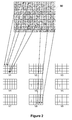
- Figure 2 shows an example of the distribution of micro-lens images projected by a micro-lens array onto the photosensor 30.
- the photosensor 30 comprises a plurality of rows and columns of pixels, and each micro-image projected onto the photosensor 30 have a diameter equal to three pixels of the photosensor 30.
- a plenoptic camera is designed so that each micro-lens image depicts a certain area of the captured scene and each pixel associated with that micro-lens image depicts this certain area from the point of view of a certain sub-aperture location on the main lens exit pupil.
- the raw image of the scene obtained as a result is the sum of all the micro-images acquired from respective portions of the photosensor 30.
- This raw image contains the angular information of the light-field. Angular information is given by the relative position of pixels in the micro-images with respect to the centre of these micro-images.
- the extraction of an image of the captured scene from a certain point of view (also called “de-multiplexing”) is performed by reorganizing the pixels of this raw image in such a way that all pixels capturing the scene with a certain angle of incidence are stored in a same pixel grid (also commonly called “view” or "sub-aperture image”).
- Each view gathers, in a predefined sequence, the pixels of the micro-images having the same relative position with respect to their respective centre (i.e. the pixels which are associated with a same given angle of view), thereby forming a pixel mosaic.
- Each sub-aperture image therefore has as many pixels as micro-lenses comprised in the micro-lens array 20 and there are usually as many sub-aperture image as pixels per micro-image.
- each micro-lens image of figure 2 covers at least partially nine pixels, thus allowing the generation of nine views (V1, V2, ..., V9) of the captured scene, each view corresponding to the scene seen from a particular viewing angle.
- a main lens is a more or less complex optical system composed of a plurality of lenses designed to image an object on the photosensor.
- Conventional optical systems possess inherent aberrations that degrade the quality of images formed by the optical system and acquired by the photosensor.
- Optical aberrations are mainly due to the convergence of rays of light passing through the optical system, depending on different well-known parameters.
- the image sharpness characterizes the quality of an optical system.
- the optical systems are designed such that the images formed on the photosensor are as sharp as possible for the range of visible wavelengths and throughout the full field of view.
- the point spread function is typically used to characterize the optical quality of the main-lens of the imaging device. It describes the impulse response of a focused optical system to a point source or point object.
- the optical systems are designed so that, for given focus and aperture parameters, a point object in the object plane is imaged to a light spot (also commonly called “spot-diagram") having an extent smaller than a given number of pixels on the photosensor. Due to the optical aberrations of the main-lens, the spot diagram is not, in practice, equal to a Dirac function but spreads over several pixels.
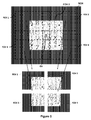
- Figure 3 shows an example of an image 300 captured by a conventional imaging device using a basic wide-angle main-lens.
- the image 300 represents a part of a test pattern.
- the image formed by the main-lens on the photosensor does not have the same image quality from the center to peripheral regions of the image.
- the black boxes 310, 320, 330, 340 illustrate the PSF spot-diagrams obtained by the main-lens a different location on the photosensor: box 310 is located in the center of the photosensor; boxes 320, 330 are located in peripheral regions of the photosensor; box 340 is located in an intermediate central region. Black boxes have been superposed to the image 300.
- the dotted circle 350 delimits a central area 311 of the image 300 in which the image is considered to be sharp (concentrated light spots 310 and 340) and a peripheral area 312 in which the image lacks of sharpness (spread light spots 320 and 330). The further from the center of the image is, the more degraded the image sharpness it is. This shows that the main-lens 110 inherently suffers optical aberrations in peripheral regions that affect the image quality particularly at the edges of the image, resulting a lack of acutance at these areas of image.
- references in the specification to "one embodiment”, “an embodiment”, “an example embodiment”, indicate that the embodiment described may include a particular feature, structure, or characteristic, but every embodiment may not necessarily include the particular feature, structure, or characteristic. Moreover, such phrases are not necessarily referring to the same embodiment. Further, when a particular feature, structure, or characteristic is described in connection with an embodiment, it is submitted that it is within the knowledge of one skilled in the art to affect such feature, structure, or characteristic in connection with other embodiments whether or not explicitly described.
- a particular embodiment of the invention proposes a plenoptic imaging device comprising a plenoptic imaging device comprising a micro-lens array placed between a main lens and a photosensor, said micro-lens array comprising a plurality of micro-lenses arranged in an image plane of the main lens, each micro-lens being configured to project a micro-image onto the photosensor, said main lens having a main optical axis and an aperture diaphragm plane, said main lens covering a field-of-view of a scene according to a capture axis centred on the main optical axis, called central field-of-view.
- the plenoptic imaging device is such that it comprises multi-faceted optical means having at least two facets and placed in a plane adjacent to the aperture diaphragm plane and centred on the main optical axis, each facet being configured to angularly rotated the capture axis with respect to the main optical axis so as to capture a rotated field-of-view from the central field-of-view, and so that the captured rotated field-of-views form an expanded field-of-view covering said central field-of-view.
- the principle of the invention is to capture an expanded field-of-view of the scene composed of multiple field-of-views rotated from the central field-of-view, each rotated field-of-view being imaged by the main lens as if it is centred on the main optical axis. Therefore, each of the rotated field-of-views allows imaging a portion of the scene with reduced or without optical aberration. Multiple decentred images of the scene can be thus obtained and, thanks to plenoptic imaging configuration, a composite image of these decentred images can be reconstituted, such composite image being of enhanced quality. Contrary to the prior art in which the peripheral portion of the image usually lacks of sharpness, such a composite image has a good level of sharpness from the center to peripheral regions of the image. Thus the invention provides a solution that improves the quality of image using a plenoptic device.
- each micro-lens covers at least partially an integer number of pixels of the photosensor, said multi-faceted optical means comprising a number of facets lower than or equal to said integer number of pixels.
- each micro-lens is configured to project micro-images onto the photosensor such that a distance between two successive micro-images projected onto the photosensor is equal to square root of said integer number of pixels.
- the photosensor comprises an ordered array of pixels arranged according to a geometric scheme and the facets of said multi-faceted optical means are geometrically arranged as a function of said geometric scheme.
- said multi-faceted optical means comprise a multi-facet prismatic element having a base and at least two lateral facets starting from said base and meeting at an apex, said apex passing through the main optical axis.
- said multi-faceted optical means comprise a multi-facet prismatic element having a base and at least two lateral facets starting from said base and meeting at a central facet, said central facet being arranged perpendicularly to and passing through the main optical axis.
- each facet of said multi-facet prismatic element forms an angle with said base that depends on:
- facets suitably oriented allows suitably capturing the different rotated field-of-views necessary to the reconstitution of a good quality image of the scene.
- the plenoptic imaging device comprises a unit for:
- first, second, etc. may be used herein to describe various elements, these elements should not be limited by these terms. These terms are only used to distinguish one element from another. For example, a first element could be termed a second element, and, similarly, a second element could be termed a first element without departing from the teachings of the disclosure.
- FIG. 4 illustrates a simplified example of a plenoptic imaging device 400 according to a particular embodiment of the present disclosure.
- the plenoptic imaging device 400 comprises a micro-lens array 420 placed between a main lens 410 and a photosensor 430.
- the micro-lens array 420 comprises a plurality of micro-lenses arranged in the image plane of the main lens 420.
- the micro-lens array 420 comprises M rows and N columns according to a rectangular-shaped geometric scheme (lattice).
- Each micro-lens has a bottom with a substantially circular contour and is configured to project a circular micro-image onto the photosensor 430 and covers a number of pixels (k) of the photosensor 430.
- each micro-lens of the micro-lens array shall be configured to cover an integer number of pixels (k).
- the photosensor 430 uses for example a CCD (Charge-Coupled Device) or CMOS (Complementary Metal Oxide Semiconductor) technology.
- the photosensor 430 consists of an ordered array of RGB pixels arranged according to a rectangular-shaped geometric scheme, (or lattice) with W pixels in width and H pixels in height.
- micro-lens array can be implemented for the pixel array of photosensor and the micro-lens array without departing from the scope of the invention, on the condition that the geometric schemes of micro-lens array and that of photosensor are identical and oriented in the same direction. This condition allows sub-aperture images to be extracted more easily.
- the micro-lens shape it is no impact on the implementation of the invention and can be of different shapes (circular, rectangular, hexagonal, etc.) .
- the main lens 410 is an optical system composed of a set of three glass lenses 411, 412, 413 and an aperture diaphragm 440 arranged on a main optical axis (referred to as OA on the figures).
- the aperture diaphragm 440 is placed in an optical plane so-called aperture diaphragm plane.
- the main lens 410 is, for example, a wide-angle objective which covers a field-of-view of a scene SCN with a given wide angle-of-view as illustrated in figure 5 .
- An angle-of-view is defined as being the angular extent of a given scene that is imaged by the imaging device and depends on the value of used focal and photosensor dimensions.
- the main lens 410 is designed to image the scene SCN according to an image-capture direction (or capture axis) that matches the optical axis OA of the main lens 410.
- the field-of-view covered by the main lens 410 is centred on the main optical axis OA; it is hereafter called central field-of-view.
- the main optical OA axis is marked with a white cross on the figure.
- FOV 0 refers to the central field-of-view that the imaging device 400 is supposed to cover without multi-facet prismatic element.
- the plenoptic imaging device 400 comprises multi-faceted optical means placed in front of the main lens 410 as closed to the diaphragm plane 440 and centred on the main optical axis OA.
- the multi-faceted optical means 450 consist of a multi-facet prismatic element 450 positioned at the entrance aperture of the main lens 410.
- the multi-facet prismatic element 450 comprises four facets designed to split the pupil of the main lens 410 and create simultaneously four field-of-views of the scene SCN which are each angularly rotated from the main optical OA and which allow covering a field-of-view more expanded than the central field-of-view FOV-0.
- multi-facet prismatic element 450 discussed hereabove as being located at the entrance aperture of the main lens 410, the present disclosure is not limited to this example.
- the multi-facet prismatic element 450 can be provided at any plane adjacent to the aperture diaphragm, advantageously, at the nearest of the aperture diaphragm.
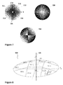
- Figure 7 shows in top view three examples of multi-facet prismatic element 710, 720, 730 for use in the imaging device according to the present disclosure.
- Each of the prismatic elements 710, 720, 730 has a base and four lateral facets starting from said base and meeting at an apex, the apex passing through the main optical axis OA.
- the facets are represented in grey areas, whose the grey scale is representative of thickness of the prism facet: white is representative of the thinnest part and dark is representative of the thickest part.
- the prismatic element 710 comprises:
- the facets 711, 712, 713, 714 are symmetrically disposed to form a pyramidal-shaped prismatic element having an apex passing through the main optical axis OA.
- each of the facets 711, 712, 713, 714 covers a quarter of the pupil of the main lens 210 and allows creating a sub-image of an expended field-of-view of the scene SCN.
- the facets 711, 712, 713, 714 are thus configured to enable the imaging device 400 to capture four rotated field-of-views FOV 1, FOV 2, FOV 3, FOV 4 which partly overlap around the main optical axis OA.
- the rotated field-of-views FOV 1, FOV 2, FOV 3, FOV 4 have each an identical angle-of-view and embrace each a distinct field-of-views of the scene SCN rotated from the central filed-of-view FOV 0 relative to the main optical axis OA.
- the white circle on the figure 5 represents the image-capture axis associated with each rotated field-of-view captured by the device and the white cross the main lens optical axis.
- the rotated field-of-views FOV 1, FOV 2, FOV 3, FOV 4 captured by the main lens 410 overlap around the main optical axis OA and form an expanded field-of-view covering the central field-of-view FOV 0.
- Each rotated field-of-view forms a partial image of the scene SCN which is projected onto the photosensor 430 via the micro-lens array 420 simultaneously with the partial images from the other rotated field-of-views.
- the function of the multi-facet prismatic element 450 is to form rotated field-of-views of the central field-of-view FOV 0 seen by the main lens 410 as if they are centred on the main optical axis OA. In that way, each rotated field-of-view allows taking advantage of the good optical performances of the main lens in areas of the captured scene usually subject to optical aberrations. Peripheral area of the field-of-view is thus captured with a reduced level of optical aberrations thanks to the multi-facet prismatic element 450.
- the facets of the multi-faceted prismatic element 710 are geometrically arranged as a function of the geometric scheme of ordered array of pixels of the photosensor 430.
- the array of pixels is disposed according to an orthogonal arrangement in a plane (O'; x', y') defined by orthogonal axes [O'x'], [O'y'].
- the facets 711, 712, 713, 714 are symmetrically disposed in relation to each other with respect to orthogonal axes [Ox], [Oy], orthogonal axes [Ox], [Oy] being parallel to orthogonal axes [O'x'], [O'y'].
- the centre of symmetry of the facets 711, 712, 713, 714 is a point merged with the main optical axis OA.
- Each facet of the multi-facet prismatic element has an angle with the base adapted to angularly deviate the field-of-view captured by the device and form an expanded field-of-view as illustrated in figure 5 .
- the prism 90 is used to deviate the photons captured by the device.
- the angle A formed with the prims base is defined so that the angle of rotation of each sub-aperture image permits to expand the field of view of the device.
- the field-of-view of the camera is given by the size of the photosensor 91 and the focal distance F of the main-lens 92.
- ⁇ refers to the angle of a half field-of-view of the camera and T refers a half length of photosensor 91.
- a prism (or a facet of multi-facet prismatic element) is characterized by an angle of rotation A.
- the prim is made from a material characterized by a refraction index n.
- Figure 9B shows that the deviation angle of a prism must be equal to the angle ⁇ .
- each facet (i,j) is associated with a sub-aperture image S(i, j) and is characterized by a two-component angle of rotation A i,j :
- a i,0 is an angle of rotation according to x-axis and
- a i,0 is an angle of rotation according to y-axis in the coordinate system (O; x, y, z).
- the main optical axis passes through the z-axis.
- the angle of rotation A i,j for the facet (i, j) is then defined as follow:
- a i , j A i , j x A i , j y
- the distance u is equal to 2.
- the photosensor is designed such that the micro-lenses are covering 2 ⁇ 2 pixels.
- a i,j of each facet (i, j) is defined as follow:
- This formulae allows to capture rotated field-of-views which are juxtaposed around the main optical axis without overlapping.
- An angle of rotation smaller than that can be envisaged in case where an overlap of rotated field-of-views is desired, like the particular example of figures 5 and 6 .
- the angle of rotation A i,j for the facet (i,j) is therefore chosen as a function of the refraction index n of the multi-facet prismatic element, the distance u, the size of the photosensor (T) and the main lens focal distance (F).
- This prismatic element 800 has a shape of truncated pyramid.
- each facet is associated with a pixel of a same position in the micro-images.
- each facet is associated with two pixels of same position in the micro-images.
- the central facet (1,1) is arranged perpendicularly to the main optical axis OA and passing through the main optical axis OA.
- the central facet (1,1) which is associated with the sub-aperture image S(1,1), has therefore null angle. In this particular configuration, the central facet allows captured an additional sub-aperture image centred on the optical axis of the imagine device.
- the facets illustrated here are designed to form multi-facet prismatic element with a circular base, but one may envisage using a multi-facet prismatic element having a polygonal base without departing from the scope of the disclosure.
- each micro-facet prismatic element 450 associated with the main lens 410 form and project a set of four sub-images superposed onto the photosensor 430 via the micro-lens array 420.
- Each superposed sub-image depicts a certain field-of-view of the scene SCN (FOV 1, FOV 2, FOV 3, FOV 4).
- Each micro-lens projects a micro-image of said set of four superposed images onto the photosensor 430.
- each micro-lens image depicts an area of the captured scene from the point-of-view of a certain sub-aperture location on the main lens exit pupil.
- a processing unit is provided for processing data acquired by the photosensor 430.
- such a unit may be embedded in the photosensor 430. In another embodiment, it may be an external unit connected to the photosensor 430.
- the processing unit first obtains a light-field content of the scene resulting from the sum of all the micro-images acquired from respective portions of the photosensor 430. Based on this a light-field content, the processing unit performs an extraction of sub-aperture images of the captured scene from different points of view by means of a de-multiplexing method. This method is based on a reorganization of the pixels of this raw image in such a way that all pixels capturing the scene with a certain angle of incidence are stored in a sub-aperture image.
- the processing unit extracts, from the light-field content, four sub-aperture images S(1,1), S(1,2), S(2,1), S(2,2).
- Extracted sub-aperture image S(1,1) is a sub-image associated with the rotated field-of-view FOV 1
- extracted sub-aperture image S(1,2) is a sub-image associated with the rotated field-of-view FOV 2
- extracted sub-aperture image S(2,1) is a sub-image associated with the rotated field-of-view FOV 3
- extracted sub-aperture image S(2,2) is a sub-image associated with the captured rotated field-of-view FOV 4.
- each extracted sub-aperture image has a good level of sharpness on the whole image with tiny PSF spot diagrams.
- the processing unit then builds a composite image CPI of the scene SCN on the basis of four sub-aperture images S(1,1), S(1,2), S(2,1), S(2,2) thus extracted from the light-field content.
- the processing unit can warp each of the four sub-aperture images S(1,1), S(1,2), S(2,1), S(2,2) according to a predefined distortion model. This allows compensating the geometric default related to the multi-facet prismatic element 450 notably.
- the four warped sub-aperture images S(1,1), S(1,2), S(2,1), S(2,2) are assembled using a known stitching method, as that described in the document " Image Stitching - Comparisons and New Techniques” of Chia-Yen Chen - October 1998 - or that described in the document “ 3D and Image Stitching With the Lytro Light-Field Camera” of William Lu et al. - 2013 - (Dept. of Comp. Sci., City College of New York, New York, NY, 2013 ), to form an extended and complete image (ECI) of the scene (also called composite image).
- ECI extended and complete image
- the shift mechanisms between sub-aperture images are deduced such that the common objects of the scene visible on two sub-aperture images match the same pixel coordinate in the composite image.
- the composite image can be further subject to a reframe process to retain only a desired area of the captured scene.
- the composite image CPI thus obtained is an enhanced quality image of the scene SCN captured by the imagine device 400. It has a constant level of sharpness from the center to peripheral regions of the image.
- the device according to the invention relies on an image quality enhancing technique combining optical multiplexing and light-field digital data demultiplexing.
Landscapes
- Physics & Mathematics (AREA)
- General Physics & Mathematics (AREA)
- Optics & Photonics (AREA)
- Engineering & Computer Science (AREA)
- Multimedia (AREA)
- Signal Processing (AREA)
- Theoretical Computer Science (AREA)
- Computer Vision & Pattern Recognition (AREA)
- Computing Systems (AREA)
- Studio Devices (AREA)
- Stereoscopic And Panoramic Photography (AREA)
- Lenses (AREA)
Priority Applications (3)
| Application Number | Priority Date | Filing Date | Title |
|---|---|---|---|
| EP16306119.5A EP3293959A1 (de) | 2016-09-07 | 2016-09-07 | Plenoptische bildgebungsvorrichtung ausgerüstet mit einem erweiterten optischen system |
| EP17188486.9A EP3293961A1 (de) | 2016-09-07 | 2017-08-30 | Plenoptische abbildungsvorrichtung mit verbessertem optischem system |
| US15/697,364 US10348947B2 (en) | 2016-09-07 | 2017-09-06 | Plenoptic imaging device equipped with an enhanced optical system |
Applications Claiming Priority (1)
| Application Number | Priority Date | Filing Date | Title |
|---|---|---|---|
| EP16306119.5A EP3293959A1 (de) | 2016-09-07 | 2016-09-07 | Plenoptische bildgebungsvorrichtung ausgerüstet mit einem erweiterten optischen system |
Publications (1)
| Publication Number | Publication Date |
|---|---|
| EP3293959A1 true EP3293959A1 (de) | 2018-03-14 |
Family
ID=56943454
Family Applications (2)
| Application Number | Title | Priority Date | Filing Date |
|---|---|---|---|
| EP16306119.5A Withdrawn EP3293959A1 (de) | 2016-09-07 | 2016-09-07 | Plenoptische bildgebungsvorrichtung ausgerüstet mit einem erweiterten optischen system |
| EP17188486.9A Withdrawn EP3293961A1 (de) | 2016-09-07 | 2017-08-30 | Plenoptische abbildungsvorrichtung mit verbessertem optischem system |
Family Applications After (1)
| Application Number | Title | Priority Date | Filing Date |
|---|---|---|---|
| EP17188486.9A Withdrawn EP3293961A1 (de) | 2016-09-07 | 2017-08-30 | Plenoptische abbildungsvorrichtung mit verbessertem optischem system |
Country Status (2)
| Country | Link |
|---|---|
| US (1) | US10348947B2 (de) |
| EP (2) | EP3293959A1 (de) |
Cited By (2)
| Publication number | Priority date | Publication date | Assignee | Title |
|---|---|---|---|---|
| CN111310554A (zh) * | 2018-12-12 | 2020-06-19 | 麦格纳覆盖件有限公司 | 数字成像系统和图像数据处理方法 |
| CN114019662A (zh) * | 2021-09-23 | 2022-02-08 | 北京控制工程研究所 | 一种基于微透镜阵列探测器的大视场照度均匀性光学系统 |
Families Citing this family (20)
| Publication number | Priority date | Publication date | Assignee | Title |
|---|---|---|---|---|
| EP3443735B1 (de) | 2016-04-12 | 2024-09-18 | Quidient, LLC | Rekonstruktionsmaschine für alltägliche szenen |
| US10930709B2 (en) | 2017-10-03 | 2021-02-23 | Lockheed Martin Corporation | Stacked transparent pixel structures for image sensors |
| US10510812B2 (en) | 2017-11-09 | 2019-12-17 | Lockheed Martin Corporation | Display-integrated infrared emitter and sensor structures |
| US10979699B2 (en) | 2018-02-07 | 2021-04-13 | Lockheed Martin Corporation | Plenoptic cellular imaging system |
| US10652529B2 (en) | 2018-02-07 | 2020-05-12 | Lockheed Martin Corporation | In-layer Signal processing |
| US10951883B2 (en) | 2018-02-07 | 2021-03-16 | Lockheed Martin Corporation | Distributed multi-screen array for high density display |
| US10690910B2 (en) | 2018-02-07 | 2020-06-23 | Lockheed Martin Corporation | Plenoptic cellular vision correction |
| US10594951B2 (en) | 2018-02-07 | 2020-03-17 | Lockheed Martin Corporation | Distributed multi-aperture camera array |
| US11616941B2 (en) | 2018-02-07 | 2023-03-28 | Lockheed Martin Corporation | Direct camera-to-display system |
| US10838250B2 (en) | 2018-02-07 | 2020-11-17 | Lockheed Martin Corporation | Display assemblies with electronically emulated transparency |
| JP7399879B2 (ja) | 2018-05-02 | 2023-12-18 | クイッディエント・エルエルシー | ほとんど無制限のディテールを有するシーンを処理するためのコーデック |
| US11156503B2 (en) * | 2018-08-06 | 2021-10-26 | Arizona Board Of Regents On Behalf Of The University Of Arizona | Wavefront sensor device and method |
| US10866413B2 (en) | 2018-12-03 | 2020-12-15 | Lockheed Martin Corporation | Eccentric incident luminance pupil tracking |
| WO2020163347A1 (en) | 2019-02-04 | 2020-08-13 | Copious Imaging Llc | Advanced computational pixel imagers with multiple in-pixel counters |
| US10698201B1 (en) | 2019-04-02 | 2020-06-30 | Lockheed Martin Corporation | Plenoptic cellular axis redirection |
| CN115128826B (zh) * | 2020-02-18 | 2023-04-25 | 中国人民解放军陆军工程大学 | 多孔径单探测器交叉视场成像系统 |
| KR102847322B1 (ko) * | 2020-04-07 | 2025-08-19 | 에스케이하이닉스 주식회사 | 이미지 센싱 장치 |
| US11328150B2 (en) * | 2020-04-30 | 2022-05-10 | Omnivision Technologies, Inc. | Lens-array imager |
| CN115509021B (zh) * | 2022-10-12 | 2025-07-15 | 北京空间机电研究所 | 一种光楔与成像镜头一体化设计的光学拼接系统 |
| CN119421055B (zh) * | 2025-01-05 | 2025-04-15 | 杭州希诺智能医学有限公司 | 对焦视场的采样方法及其相关设备 |
Citations (4)
| Publication number | Priority date | Publication date | Assignee | Title |
|---|---|---|---|---|
| JP2012129654A (ja) * | 2010-12-13 | 2012-07-05 | Canon Inc | 撮像装置及びその制御方法、プログラム |
| US20130222633A1 (en) | 2012-02-28 | 2013-08-29 | Lytro, Inc. | Light-field processing and analysis, camera control, and user interfaces and interaction on light-field capture devices |
| WO2015091509A1 (de) * | 2013-12-19 | 2015-06-25 | Fraunhofer-Gesellschaft zur Förderung der angewandten Forschung e.V. | Mehrkanaloptik-bildaufnahmevorrichtung |
| EP3007228A1 (de) * | 2013-05-21 | 2016-04-13 | Jorge Vicente Blasco Claret | Monolithische integration von plenoptischen linsen auf fotosensorsubstraten |
Family Cites Families (13)
| Publication number | Priority date | Publication date | Assignee | Title |
|---|---|---|---|---|
| JPH08233658A (ja) * | 1995-02-24 | 1996-09-13 | Olympus Optical Co Ltd | 分光装置及び分光画像記録装置 |
| JP3409587B2 (ja) * | 1996-05-14 | 2003-05-26 | オムロン株式会社 | 光路変換光学素子、画像表示装置及び光投射器 |
| US6483535B1 (en) | 1999-12-23 | 2002-11-19 | Welch Allyn, Inc. | Wide angle lens system for electronic imagers having long exit pupil distances |
| US20060215054A1 (en) | 2005-03-23 | 2006-09-28 | Eastman Kodak Company | Wide angle camera with prism array |
| US7620309B2 (en) * | 2006-04-04 | 2009-11-17 | Adobe Systems, Incorporated | Plenoptic camera |
| JP4259541B2 (ja) * | 2006-04-18 | 2009-04-30 | 船井電機株式会社 | パノラマ撮像装置 |
| US8290358B1 (en) * | 2007-06-25 | 2012-10-16 | Adobe Systems Incorporated | Methods and apparatus for light-field imaging |
| US8559756B2 (en) * | 2007-08-06 | 2013-10-15 | Adobe Systems Incorporated | Radiance processing by demultiplexing in the frequency domain |
| JP2014066897A (ja) | 2012-09-26 | 2014-04-17 | Fujifilm Corp | 領域分割レンズ及びプレノプティックカメラ |
| CN204258928U (zh) | 2014-11-03 | 2015-04-08 | 北京蚁视科技有限公司 | 光场成像系统 |
| US9902120B2 (en) * | 2015-02-09 | 2018-02-27 | Omnivision Technologies, Inc. | Wide-angle camera using achromatic doublet prism array and method of manufacturing the same |
| KR102297488B1 (ko) * | 2015-02-17 | 2021-09-02 | 삼성전자주식회사 | 라이트 필드 카메라 |
| US10291866B2 (en) * | 2016-06-24 | 2019-05-14 | Moondog Optics, Inc. | Lens attachment for multi-camera device |
-
2016
- 2016-09-07 EP EP16306119.5A patent/EP3293959A1/de not_active Withdrawn
-
2017
- 2017-08-30 EP EP17188486.9A patent/EP3293961A1/de not_active Withdrawn
- 2017-09-06 US US15/697,364 patent/US10348947B2/en active Active
Patent Citations (4)
| Publication number | Priority date | Publication date | Assignee | Title |
|---|---|---|---|---|
| JP2012129654A (ja) * | 2010-12-13 | 2012-07-05 | Canon Inc | 撮像装置及びその制御方法、プログラム |
| US20130222633A1 (en) | 2012-02-28 | 2013-08-29 | Lytro, Inc. | Light-field processing and analysis, camera control, and user interfaces and interaction on light-field capture devices |
| EP3007228A1 (de) * | 2013-05-21 | 2016-04-13 | Jorge Vicente Blasco Claret | Monolithische integration von plenoptischen linsen auf fotosensorsubstraten |
| WO2015091509A1 (de) * | 2013-12-19 | 2015-06-25 | Fraunhofer-Gesellschaft zur Förderung der angewandten Forschung e.V. | Mehrkanaloptik-bildaufnahmevorrichtung |
Non-Patent Citations (2)
| Title |
|---|
| CHIA-YEN CHEN, IMAGE STITCHING - COMPARISONS AND NEW TECHNIQUES, October 1998 (1998-10-01) |
| WILLIAM LU ET AL., 3D AND IMAGE STITCHING WITH THE LYTRO LIGHT-FIELD CAMERA, 2013 |
Cited By (3)
| Publication number | Priority date | Publication date | Assignee | Title |
|---|---|---|---|---|
| CN111310554A (zh) * | 2018-12-12 | 2020-06-19 | 麦格纳覆盖件有限公司 | 数字成像系统和图像数据处理方法 |
| CN111310554B (zh) * | 2018-12-12 | 2023-10-31 | 麦格纳覆盖件有限公司 | 数字成像系统和图像数据处理方法 |
| CN114019662A (zh) * | 2021-09-23 | 2022-02-08 | 北京控制工程研究所 | 一种基于微透镜阵列探测器的大视场照度均匀性光学系统 |
Also Published As
| Publication number | Publication date |
|---|---|
| US10348947B2 (en) | 2019-07-09 |
| EP3293961A1 (de) | 2018-03-14 |
| US20180067237A1 (en) | 2018-03-08 |
Similar Documents
| Publication | Publication Date | Title |
|---|---|---|
| US10348947B2 (en) | Plenoptic imaging device equipped with an enhanced optical system | |
| US11736676B2 (en) | Imaging apparatus and image sensor array | |
| US9204067B2 (en) | Image sensor and image capturing apparatus | |
| CN102385168B (zh) | 将像素矩阵划分为子组的立体成像方法和系统 | |
| US9167148B2 (en) | Image capture apparatus that performs focus detection with a phase difference detection method | |
| Horstmeyer et al. | Flexible multimodal camera using a light field architecture | |
| US20090219432A1 (en) | Sensor with multi-perspective image capture | |
| US20120300041A1 (en) | Image capturing device | |
| US12197106B2 (en) | Image sensor and image-capturing device that selects pixel signal for focal position | |
| CN105635530B (zh) | 光场成像系统 | |
| CN107004685A (zh) | 固体摄像器件和电子装置 | |
| KR20170032227A (ko) | 복안 촬상 장치 | |
| US20200244881A1 (en) | Imaging system, method, and applications | |
| CN107005640A (zh) | 图像传感器单元和成像装置 | |
| US20160261809A1 (en) | Disparity in Plenoptic Systems | |
| JP2015188251A (ja) | 画像処理装置、撮像装置、画像処理方法、及びプログラム | |
| JP4472166B2 (ja) | 3次元撮像装量 | |
| EP3104604A1 (de) | Lichtfeldabbildungsvorrichtung | |
| EP3522106A1 (de) | Filteranordnung, die eine einfache entmosaikierung ermöglicht | |
| US20160252805A1 (en) | Optical device for capturing images in a 360° horizontal field of view | |
| EP3104593A1 (de) | Lichtfeldabbildungsvorrichtung | |
| EP3533216B1 (de) | Optische anordnung zum fokussieren von bildern eines dreidimensionalen raumes aus verschiedenen divergenten perspektiven auf einen kamerasensor | |
| JP2017098929A (ja) | 画像処理装置および画像処理方法 |
Legal Events
| Date | Code | Title | Description |
|---|---|---|---|
| PUAI | Public reference made under article 153(3) epc to a published international application that has entered the european phase |
Free format text: ORIGINAL CODE: 0009012 |
|
| AK | Designated contracting states |
Kind code of ref document: A1 Designated state(s): AL AT BE BG CH CY CZ DE DK EE ES FI FR GB GR HR HU IE IS IT LI LT LU LV MC MK MT NL NO PL PT RO RS SE SI SK SM TR |
|
| AX | Request for extension of the european patent |
Extension state: BA ME |
|
| STAA | Information on the status of an ep patent application or granted ep patent |
Free format text: STATUS: THE APPLICATION IS DEEMED TO BE WITHDRAWN |
|
| 18D | Application deemed to be withdrawn |
Effective date: 20180915 |