EP3293973A1 - Dispositif électronique et son procédé de commande - Google Patents
Dispositif électronique et son procédé de commande Download PDFInfo
- Publication number
- EP3293973A1 EP3293973A1 EP16855752.8A EP16855752A EP3293973A1 EP 3293973 A1 EP3293973 A1 EP 3293973A1 EP 16855752 A EP16855752 A EP 16855752A EP 3293973 A1 EP3293973 A1 EP 3293973A1
- Authority
- EP
- European Patent Office
- Prior art keywords
- view
- distance
- virtual field
- field
- electronic device
- Prior art date
- Legal status (The legal status is an assumption and is not a legal conclusion. Google has not performed a legal analysis and makes no representation as to the accuracy of the status listed.)
- Ceased
Links
Images







Classifications
-
- G—PHYSICS
- G02—OPTICS
- G02B—OPTICAL ELEMENTS, SYSTEMS OR APPARATUS
- G02B27/00—Optical systems or apparatus not provided for by any of the groups G02B1/00 - G02B26/00, G02B30/00
- G02B27/01—Head-up displays
- G02B27/017—Head mounted
- G02B27/0172—Head mounted characterised by optical features
-
- G—PHYSICS
- G06—COMPUTING OR CALCULATING; COUNTING
- G06F—ELECTRIC DIGITAL DATA PROCESSING
- G06F3/00—Input arrangements for transferring data to be processed into a form capable of being handled by the computer; Output arrangements for transferring data from processing unit to output unit, e.g. interface arrangements
- G06F3/01—Input arrangements or combined input and output arrangements for interaction between user and computer
- G06F3/011—Arrangements for interaction with the human body, e.g. for user immersion in virtual reality
-
- G—PHYSICS
- G06—COMPUTING OR CALCULATING; COUNTING
- G06T—IMAGE DATA PROCESSING OR GENERATION, IN GENERAL
- G06T15/00—Three-dimensional [3D] image rendering
- G06T15/10—Geometric effects
- G06T15/20—Perspective computation
-
- H—ELECTRICITY
- H04—ELECTRIC COMMUNICATION TECHNIQUE
- H04N—PICTORIAL COMMUNICATION, e.g. TELEVISION
- H04N13/00—Stereoscopic video systems; Multi-view video systems; Details thereof
- H04N13/30—Image reproducers
-
- H—ELECTRICITY
- H04—ELECTRIC COMMUNICATION TECHNIQUE
- H04W—WIRELESS COMMUNICATION NETWORKS
- H04W4/00—Services specially adapted for wireless communication networks; Facilities therefor
- H04W4/02—Services making use of location information
-
- G—PHYSICS
- G02—OPTICS
- G02B—OPTICAL ELEMENTS, SYSTEMS OR APPARATUS
- G02B27/00—Optical systems or apparatus not provided for by any of the groups G02B1/00 - G02B26/00, G02B30/00
- G02B27/01—Head-up displays
- G02B27/0101—Head-up displays characterised by optical features
- G02B2027/0123—Head-up displays characterised by optical features comprising devices increasing the field of view
Definitions
- the present invention pertains to an electronic device and a controlling method thereof and, more particularly, to an electronic device which provides a virtual reality (VR) service and a controlling method thereof.
- VR virtual reality
- VR virtual reality
- CG computer graphic
- An electronic device includes a display configured to display a virtual reality (VR) content; a detection unit configured to detect a distance between the electronic device and at least one of a user and a terminal device held by the user; and a processor configured to determine a virtual field of view corresponding to the distance detected by the detection unit and control the display to display a screen including a VR content area corresponding to the virtual field of view.
- VR virtual reality
- the processor may, in response to the virtual field of view being a field of view based on a user and the detected distance being increased than a previously-sensed distance, increase the virtual field of view, and in response to the detected distance being decreased than a previously-detected distance, decrease the virtual field of view.
- the processor may, in response to the virtual field of view being a field of view based on the electronic device and the detected distance being increased than a previously-sensed distance, decrease the virtual field of view, and in response to the detected distance being decreased than a previously-detected distance, increase the virtual field of view.
- the processor may control the display to change the virtual field of view by a predetermined ratio corresponding to a changed distance according to a change in the detected distance and display a screen including a VR content area corresponding to the changed virtual field of view.
- the processor may change the predetermined ratio and apply the same according to at least one of an event to input a user, an event to input a specific type content, and an event in which the sensed distance satisfies a predetermined threshold distance.
- the processor may operate in a field of view change mode which changes the virtual field of view according to the sensed distance or a field of view fixing mode which maintains the virtual field of view regardless of the sensed distance.
- the detection unit may be implemented as at least one of a camera, an RF sensor, an ultrasonic sensor, a laser sensor, and an infrared sensor.
- the processor may extract and display a screen including a content area corresponding to the virtual field of view from the VR content in which a content is reflected in a virtual three-dimensional space.
- the processor may, when a plurality of users are detected by the detection unit, determine a virtual field of view which corresponds to a distance with a predetermined user from among the plurality of users or an average distance of the plurality of users.
- a controlling method of an electronic device includes determining a virtual field of view corresponding to a distance sensed by the detection unit; and controlling the display to display a screen comprising a VR content area corresponding to the virtual field of view.
- an electronic device may include a display displaying a VR content and a detection unit which detects a distance between the electronic device and at least one of a user and a terminal device held by the user.
- controlling method may further include, in response to the virtual field of view being a field of view based on a user and the detected distance being increased than a previously-sensed distance, increasing the virtual field of view, and in response to the detected distance being decreased than a previously-detected distance, decreasing the virtual field of view.
- the controlling method may further include, in response to the virtual field of view being a field of view based on the electronic device and the detected distance being increased than a previously-sensed distance, decreasing the virtual field of view, and in response to the detected distance being decreased than a previously-detected distance, increasing the virtual field of view.
- the controlling method may further include controlling the display to change the virtual field of view by a predetermined ratio corresponding to a changed distance according to a change in the detected distance and display a screen including a VR content area corresponding to the changed virtual field of view.
- the controlling method may further include changing the predetermined ratio and applying the same according to at least one of an event to input a user, an event to input a specific type content, and an event in which the sensed distance satisfies a predetermined threshold distance.
- the controlling method may further include operating in a field of view change mode which changes the virtual field of view according to the sensed distance or a field of view fixing mode which maintains the virtual field of view regardless of the sensed distance.
- the detection unit may be implemented as at least one of a camera, an RF sensor, an ultrasonic sensor, a laser sensor, and an infrared sensor.
- the controlling method may further include extracting and displaying a screen including a content area corresponding to the virtual field of view from the VR content in which a content is reflected in a virtual three-dimensional space.
- the controlling method further including, when a plurality of users are detected by the detection unit, determining a virtual field of view which corresponds to a distance with a predetermined user from among the plurality of users or an average distance of the plurality of users.
- VR content having a virtual field of view corresponding to the distance between a user and an electronic device can be provided to provide a user with an optimal feeling of immersion.
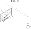
- FIGS. 1A and 1B are views illustrating an example of an electronic device 100 according to an exemplary embodiment.
- a VR device that is, an electronic device 100 according to an exemplary embodiment may be implemented as a general display device 100.
- the display device 100 may determine a virtual field of view by measuring the distance between the display device 100 and a user 10 by various distance measuring methods.
- the field of view refers to a range in which eye sight of a person reaches
- a virtual field of view refers to a predetermined field of view corresponding to the distance between the electronic device 100 and the user 10 in order to provide a sense of space to the user 10. Since the maximum field of view of a person corresponds to 100 to 120 degrees, the maximum range of the virtual field of view can also be set to 100 to 120 degrees.
- the display device 100 may display the VR contents of the first virtual field of view corresponding to the distance A.
- the display device 100 may display a VR content in a second virtual field of view having a greater value than the first virtual field of view.
- the VR may include augmented reality in which information is displayed in three dimensions overlaid on a screen or the like.
- the electronic device 100 can operate in combination with a device such as a remote control, a game console, and a 3D glasses.
- the electronic device 100 may be in various forms such as a TV, a monitor, a mobile phone, a PDA, an electronic dictionary, an MP3, a PMP, a tablet PC, and the like.
- the electronic device 100 can detect the distance between the electronic device 100 and the user 10, change the virtual field of view based on the detected distance, and display the changed field of view by applying the changed field of view to the VR content.
- the present invention will be described in detail with reference to the drawings.
- FIG. 2 is a block diagram to illustrate a configuration of an electronic device 100 according to an exemplary embodiment.
- the electronic device 100 includes a display 100, a detection unit 120, and a processor 130.
- the electronic device 100 may receive VR content from the outside, or may generate VR content based on data input from the outside.
- the display 110 displays VR content.
- the VR content may be a general two-dimensional image, but is not limited thereto, and may be a 3D image including a left-eye and right-eye image for providing a VR service, or a panorama VR content.
- the display 100 can also display VR contents to which a virtual field of view corresponding to the distance between the electronic device 100 and the user 10 is applied, under the control of the processor 130.
- the detection unit 120 may detect the distance between the electronic device 100 and at least one of the user 10 and the terminal device the user 10 holds.
- the detection unit 120 may detect the distance between the electronic device 100 and the user 10.
- the reference points for detecting the distance between the electronic device 100 and the user 10 may vary.
- the reference point may be the display 100, a bezel (not shown), a pedestal (not shown), the detection unit 120, etc., which are part of the electronic device 100.
- all the body parts of the user 10 or the entire body may be the reference point.
- the detection unit 120 may transmit distance information to the processor 130 that detects the reference point.
- the detection unit 120 may transmit detection information about a part of users or all users among the distance information detected from a plurality of users to the processor 130.
- the detection unit 120 may detect the distance between the electronic device 100 and the terminal device held by the user 10.
- the terminal device provided by the user 10 may be a variety of terminal devices such as a remote controller for controlling a display device, a joystick for operating a game, and a mobile phone.
- the detection unit 120 may indirectly detect the user 10 by sensing a terminal device provided by the user 10.
- the detection unit 120 may be implemented by at least one of a camera, an RF sensor, an ultrasonic sensor, a laser sensor, and an infrared sensor.
- the camera can photograph at least one of the user 10 and the terminal devices provided by the user 10.
- the processor 130 which will be described later, may perform a camera calibration to determine intrinsic parameters, extrinsic parameters between the camera coordinate system and the camera coordinate system. After this process, the processor 130 may extract the terminal device of the user 10 or the user 10 from a plurality of images and measure the distance.
- the camera 130 may be two or more cameras. At this time, the processor 130 may simultaneously acquire images from two or more cameras and measure distances by matching between images. In the meantime, the camera may be provided at a portion of the electronic device 100 or at a location spaced from the electronic device 100 via an extension.
- the RF sensor measures distance using radio frequency (RF).
- RF radio frequency
- the RF sensor emits an electromagnetic wave (usually 1 MHz or more) corresponding to a microwave to a terminal device of the user 10 or the user 10. It is possible to receive the microwave reflected back from the terminal device of the user 10 or the user 10 and to measure the time when the microwave is reflected and returned to the RF sensor.
- Ultrasonic sensors use ultrasonic waves to measure distances.
- ultrasound ultrasonic
- the ultrasonic sensor generates ultrasonic waves by using a piezoelectric element (a device that generates voltage when applied with mechanical pressure, and mechanical change is generated when voltage is applied).
- the ultrasonic sensor can measure the time when the ultrasonic waves are reflected from the terminal device of the user 10 or the user 10.
- the laser sensor measures the distance using a laser.
- the laser sensor emits and detects the laser using the laser transmitter and the laser receiver.
- the laser sensor emits a laser pulse signal to measure the time at which the reflection pulse signals from the user 10 or the user 10 within the measurement range arrive at the laser receiver.
- the laser sensor emits a continuously modulated laser beam with a specific frequency and measures the amount of phase variation of the signal reflected back from the user 10 or user terminal 10 within the measurement range.
- Infrared sensors measure distances using infrared (wavelengths above 900 nm).
- the infrared sensor may emit an infrared signal and measure the amount of infrared light reflected by the user 10 or the terminal 10 provided by the user 10.
- the infrared sensor can measure the distance by using a correlation in which the reflection amount of infrared rays is inversely proportional to the distance square.
- the distance measurement method described above may be measured using a variety of known sensing techniques as well as a camera, an RF sensor, an ultrasonic sensor, a laser sensor, and an infrared sensor.
- the distance is measured by a camera, an RF sensor, an ultrasonic sensor, a laser sensor, and an infrared sensor itself.
- the RF sensor, the ultrasonic sensor, the laser sensor, and the infrared sensor it is also possible that the collected data is processed by the processor 130 and the distance is measured.
- the user 10 is a single user.
- a virtual field of view corresponding to a distance from the user or an average distance of a plurality of users can be determined.
- the predetermined user may be set as the closest person or the largest person among a plurality of users, and the average distance of the plurality of users may be an average of a distance of some of the plurality of users.
- the detection unit 120 may sense the up, down, left, and right movements of the terminal of the user 10.
- the detection unit 120 may further include a sensor, such as a RADAR, having a function of identifying a position of the user 10 in accordance with the up, down, left, and right movement of the terminal.
- the processor 130 may move the VR contents area up, down, left, and right according to the vertical, horizontal, and left positions of the terminal of the user 10 detected by the detection unit 120.
- the processor 130 controls the overall operation of electronic device 100.
- the processor 130 may determine a virtual field of view corresponding to the distance sensed by the detection unit 120.
- the processor 130 may use a table in which a virtual field of view matching the sensed distance is recorded.
- the processor 130 may receive the distances between the electronic device 100 and the user 10 received via the detection unit 120. At this time, when the received distance is 2 m, the processor 130 can determine a virtual field of view corresponding to the distance 2 m to 90 degrees with reference to the table.
- the type matched to the sensed distance is described as a virtual field of view, but the type matched to the sensed distance may be the coordinate value in the VR space.
- the processor 130 can control the display 110 to display a screen including the VR contents area corresponding to the virtual field of view.
- the processor 130 may control to extract and display a screen including a content area corresponding to a virtual field of view in the VR content in which content is projected in a virtual three-dimensional space.
- the processor 130 may update the coordinates of the content area corresponding to the updated virtual field of view.
- the processor 130 may increase or decrease the coordinate value matching the content area according to the variation ratio of the virtual field of view.
- the coordinate value may be in pixel units.
- the processor 130 can change the virtual field of view as well.
- the processor 130 changes the virtual field of view by a predetermined ratio corresponding to the changed distance as the sensed distance is changed, and displays the screen including the VR contents area corresponding to the changed virtual field of view 110.
- the processor 130 changes a predetermined ratio and applies the changed ratio according to at least one of an event that a user 10 command is input, an event that a specific type of content is input, and an event of which sensed distance satisfies a predetermined threshold distance.
- the predetermined ratio is a ratio for increasing or decreasing the virtual field of view in accordance with the increase or decrease of the sensed distance.
- the processor 130 may change the preset ratio according to an event in which the command of the user 10 is input. This will be described with reference to FIG. 3 .
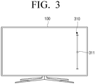
- FIG. 3 is a drawing which illustrates a GUI for changing a preset ratio according to an exemplary embodiment.
- the processor 130 outputs a Graphic User Interface (GUI) for adjusting a predetermined ratio on the display 110.
- GUI Graphic User Interface
- the GUI 310 for adjusting the predetermined ratio includes an adjustment GUI 311 that can be moved upward and downward by the operation of the user 10.
- a predetermined ratio is increased
- a predetermined ratio is decreased.
- the preset ratio increases, the ratio of the virtual field of view increases or decreases as the sensed distance increases.
- the predetermined ratio is decreased, the ratio of the virtual field of view that is increased or decreased increases as the sensed distance decreases.
- GUI is only an example, and the GUI may be implemented in various examples in order to receive an input for adjusting a predetermined ratio from the user.
- the processor 130 may change a preset ratio according to an event that a specific type of content is input.
- the processor 130 may set the predetermined ratio to a larger value so that it is possible to increase the ratio of change of the size of the virtual field of view corresponding to the change of the distance between the electronic device 100 and the user or the electronic device 100 and the terminal device of the user.
- the processor 130 may set a predetermined ratio to a smaller value so that the change ratio of the size of the virtual field of view corresponding to the change in the distance between the electronic device 100 and the user or the terminal device of the user 10 can be reduced.
- the processor 130 may change the predetermined ratio according to an event that the sensed distance satisfies a predetermined threshold distance.
- the processor 130 may reduce a predetermined ratio of changing the virtual field of view corresponding to the change in the sensed distance when the sensed distance is out of the predetermined threshold distance.
- the processor 130 may stop the increase or decrease of the virtual field of view when the predetermined sensing distance satisfies the predetermined threshold distance.
- the processor 130 may increase or decrease, decrease or increase the virtual field of view depending on the increase or decrease of the sensed distance. This will be described in detail with reference to FIGS. 4A and 4B .
- FIGS. 4A and 4B are views to describe changing a field of view based on a user according to an exemplary embodiment.
- FIGS. 4A and 4B show a change in the field of view based on the user 10.
- the VR contents include images of all areas on a three-dimensional space.
- viewing an area of the VR content through the display 110 of the electronic device 100 may be assumed as if the user 10 views an area 420 of the sphere 410 within the sphere 410.
- one area 420 of the sphere 410 is one wall
- the user 10 moves closer to the wall.
- the field of view of the user 10 decreases.
- the processor 130 increases the virtual field of view when the sensed distance is greater than the previously sensed distance, and if the sensed distance decreases than the previously sensed distance, a virtual field of view can be reduced.
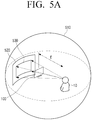
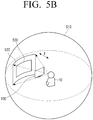
- FIGS. 5A and 5B are views to describe changing a field of view based on a display device according to an exemplary embodiment.
- FIG. 5A and 5B show the field of view changes based on the electronic device 100.
- the user 10 may be located at a distance of E from the electronic device 100 and views an area 530 of the sphere 510, through a window, that is, the electronic device 100.
- the user 10 is located in an area which is distant from the electronic device 100 by a distance F. That is, the user 10 has moved closer to the electronic device 100 than in FIG. 5A (E> F).
- the user 10 looks at one area 520 of the sphere 510 through the window, that is, the electronic device 100. As such, when the user 10 becomes closer to the electronic device 100, the field of view of the user 10 increases.
- the processor 130 may reduce the virtual field of view if the virtual field of view is a field of view of the electronic device reference, and if the sensed distance is greater than the previously sensed distance, it is also possible to increase the virtual field of view.
- FIG. 6 is a flowchart to describe a process of changing a field of view according to a sensed distance according to an exemplary embodiment.
- VR content may be input to the electronic device 100 (S610).
- the processor 130 is also capable of receiving VR content from the outside and generating VR contents.
- the processor 130 sets an initial value for the virtual field of view (S620).
- the initial value may be a virtual field of view corresponding to the type of the VR content or a field of view corresponding to the distance of the user at the time of setting the initial value.
- the processor 130 determines whether to fix the virtual field of view (S630).
- the processor 130 may determine whether to fix the field of view according to the type of the VR content, or may determine whether to fix the field of view by receiving the input of the user 10.
- the processor 130 may operate in a field-of-view changing mode that changes the virtual field of view depending on the sensed distance, or a field-of-view fixed mode that maintains the virtual field of view regardless of the sensed distance.
- the processor 130 controls the display 110 to display the VR content. If it is determined that the virtual field of view is not fixed (N), the ration that the virtual field of view is changed in response to the change in the sensed distance may be set (S640).
- the processor may determine the ratio according to the type of the VR content, or may receive the input from the user 10 and determine the ratio.
- the processor 130 uses the detection unit 120 to measure the distance between the electronic device 100 and the user or between the terminal devices owned by the user (S650).
- the processor 130 may change the virtual field of view based on the sensed distance (S660). Thereafter, the processor 130 may control the display 110 to display the VR content area to which the changed virtual field of view is applied (S670). The processor 130 may update the virtual field of view by sensing the distance between the electronic device 100 and the user or the distance between the terminal device of the user at predetermined time intervals.
- FIG. 7 is a block diagram which illustrates a detailed configuration of an electronic device 100' according to another exemplary embodiment.
- an electronic device 100' includes a display 110, a detection unit 120, a controller 130, a storage 140, and a communicator 150.
- the parts of a detailed description of FIG. 7 overlapping with those shown in FIG. 2 in the configuration shown in FIG. 7 will be omitted.
- the display 110 displays VR content.
- the display 110 may be implemented as an Liquid Crystal Display (LCD Panel), an Organic Light Emitting Diodes (OLED), or the like, but is not limited thereto.
- the display 110 may be implemented as a flexible display, a transparent display, or the like as the case may be.
- the smartphone is connected and used as a monitor, the display 110 can be implemented as a display of a smartphone.
- the detection unit 120 may sense the user 10 or the terminal device of the user 10.
- the detection unit 120 may be connected to a line extending from the electronic device 100'.
- An operation of the processor 130 may be implemented by a stored program.
- the processor 130 includes RAM 131, ROM 132, main CPU 133, graphic processor 134, first to n th interface 135-1 ⁇ 135-n, and bus 136.
- the RAM 131, ROM 132, main CPU 133, graphic processor 134, first to n th interface 135-1 ⁇ 135-n may be interconnected through the bus 136.
- the first to n th interfaces 135-1 to 135-n are connected to the various components described above.
- One of the interfaces may be a network interface connected to an external device via a network.
- the main CPU 133 accesses the storage 140 and performs booting using the O / S stored in the storage 140. Then, various operations are performed using various programs, contents, data, and the like stored in the storage 140. For example, the main CPU 133 may use the table stored in the storage 140 to determine a virtual field of view corresponding to the sensed distance.
- the ROM 132 stores a command set for booting the system and the like.
- the main CPU 133 copies the O / S stored in the storage 140 to the RAM 131 according to the command stored in the ROM 132 and executes O / S to boot the system.
- the main CPU 133 copies various application programs stored in the storage 140 to the RAM 131, executes the application program copied to the RAM 131, and performs various operations.
- the graphic processer 134 generates a screen including various objects such as an icon, an image, and a text using an operation unit (not shown) and a rendering unit (not shown).
- An operation unit (not shown) calculates an attribute value such as a coordinate value, a shape, a size, and a color with which each object is displayed according to the layout of the screen based on the received control command.
- the rendering unit (not shown) generates screens of various layouts including the objects based on the attribute values calculated by the operation unit (not shown).
- the storage 140 may store various data such as an O / S software module for driving the electronic device 100' and various multimedia contents.
- the storage 150 may store information of virtual field of view corresponding to the sensed distance according to an exemplary embodiment.
- the storage 140 may store data for generating a control signal corresponding to a user command input through various UI screens.
- the communicator 150 performs communication with an external device.
- the communicator 150 may communicate with an external device through various communication methods such as BlueTooth (BT), Wireless Fidelity (WI-FI), Zigbee, IR, Serial Interface, Universal Serial Bus.
- BT BlueTooth
- WI-FI Wireless Fidelity
- IR Zigbee
- IR Serial Interface
- Universal Serial Bus Universal Serial Bus
- the communicator 150 may receive position information from a terminal held by the user 10.
- the terminal held by the user 10 may include, for example, a gyro sensor.
- the terminal of the user 10 can transmit location information corresponding to the top, bottom, left, and right of the terminal of the user 10 sensed by the gyro sensor to the electronic device 100'.
- the processor 130 can move and display the area of the VR contents based on the location information of the terminal of the user 10. For example, when the position of the terminal of the user 10 is shifted to the left, the processor 130 can move and display the area of the VR contents to the left.
- the communicator 150 may receive a signal corresponding to an input of a upper, lower, right, and left movement button of a terminal provided by the user 10 from a terminal provided by the user 10. For example, when the processor 130 receives a signal corresponding to an input of the left movement button of the terminal of the user 10, the processor 130 may move the area of the VR contents to the left and display the same. As such, the electronic device 100' may display the entire upper, lower, right, and left areas of the VR contents according to the input of the user 10, thereby faithfully providing the user 10 with the experience of the VR contents.
- FIG. 8 is a flowchart to describe a controlling method of an electronic device according to an exemplary embodiment.
- a virtual field of view corresponding to a distance sensed by the detection unit is determined (S810), and the display may be controlled to display a screen including the corresponding VR content area (S820).
- the electronic device may be implemented as a display for displaying Virtual Reality (VR) contents, and a detection unit for sensing a distance between the user and at least one of the terminal devices provided by the user and the electronic device.
- VR Virtual Reality
- the controlling method may further include increasing the virtual field of view when the virtual field of view is a field of view based on a user and when the detected distance is greater than the previously sensed distance, and if the sensed distance is smaller than the previously sensed distance, decreasing the virtual field of view.
- the controlling method may further include, in response to the virtual field of view being a field of view based on a user and the detected distance being increased than a previously-sensed distance, increasing the virtual field of view, and in response to the detected distance being decreased than a previously-detected distance, decreasing the virtual field of view.
- the controlling method may further include controlling the display to change the virtual field of view by a predetermined ratio corresponding to a changed distance according to a change in the detected distance and display a screen including a VR content area corresponding to the changed virtual field of view.
- the controlling method may further include changing the predetermined ratio and applying the same according to at least one of an event to input a user, an event to input a specific type content, and an event in which the sensed distance satisfies a predetermined threshold distance.
- the controlling method may further include operating in a field of view change mode which changes the virtual field of view according to the sensed distance or a field of view fixing mode which maintains the virtual field of view regardless of the sensed distance.
- the detection unit may be implemented as at least one of a camera, an RF sensor, an ultrasonic sensor, a laser sensor, and an infrared sensor.
- the controlling method may further include extracting and displaying a screen including a content area corresponding to the virtual field of view from the VR content in which a content is reflected in a virtual three-dimensional space.
- the controlling method further including, when a plurality of users are detected by the detection unit, determining a virtual field of view which corresponds to a distance with a predetermined user from among the plurality of users or an average distance of the plurality of users.
- the methods according to various embodiments may be programmed and stored in various storage media. Accordingly, the methods according to various embodiments described above can be implemented in various types of electronic devices that execute the storage medium.
- a non-transitory computer readable medium in which a program to sequentially performs the step of determining a virtual field of view corresponding to a distance sensed by the detection unit and controlling a display to display a screen including VR content area corresponding to the virtual field of view is stored can be provided.
- the non-transitory computer-recordable medium is not a medium configured to temporarily store data such as a register, a cache, or a memory but an apparatus-readable medium configured to semi-permanently store data.
- the above-described various applications or programs may be stored in the non-transitory apparatus-readable medium such as a compact disc (CD), a digital versatile disc (DVD), a hard disc, a Blu-ray disc, a universal serial bus (USB), a memory card, or a read only memory (ROM), and provided therein.
Landscapes
- Engineering & Computer Science (AREA)
- Physics & Mathematics (AREA)
- Theoretical Computer Science (AREA)
- Signal Processing (AREA)
- General Physics & Mathematics (AREA)
- General Engineering & Computer Science (AREA)
- Computer Networks & Wireless Communication (AREA)
- Multimedia (AREA)
- Human Computer Interaction (AREA)
- Optics & Photonics (AREA)
- Computer Graphics (AREA)
- Geometry (AREA)
- Computing Systems (AREA)
- User Interface Of Digital Computer (AREA)
- Controls And Circuits For Display Device (AREA)
Applications Claiming Priority (2)
| Application Number | Priority Date | Filing Date | Title |
|---|---|---|---|
| KR1020150143569A KR102402048B1 (ko) | 2015-10-14 | 2015-10-14 | 전자 장치 및 그 제어 방법 |
| PCT/KR2016/011510 WO2017065535A1 (fr) | 2015-10-14 | 2016-10-13 | Dispositif électronique et son procédé de commande |
Publications (2)
| Publication Number | Publication Date |
|---|---|
| EP3293973A1 true EP3293973A1 (fr) | 2018-03-14 |
| EP3293973A4 EP3293973A4 (fr) | 2018-08-29 |
Family
ID=58517423
Family Applications (1)
| Application Number | Title | Priority Date | Filing Date |
|---|---|---|---|
| EP16855752.8A Ceased EP3293973A4 (fr) | 2015-10-14 | 2016-10-13 | Dispositif électronique et son procédé de commande |
Country Status (5)
| Country | Link |
|---|---|
| US (1) | US10422996B2 (fr) |
| EP (1) | EP3293973A4 (fr) |
| KR (1) | KR102402048B1 (fr) |
| CN (1) | CN107637076B (fr) |
| WO (1) | WO2017065535A1 (fr) |
Families Citing this family (10)
| Publication number | Priority date | Publication date | Assignee | Title |
|---|---|---|---|---|
| KR102172517B1 (ko) | 2017-04-04 | 2020-10-30 | 주식회사 엘지화학 | 크래쉬 빔 구조를 갖는 배터리 팩 |
| CN106990537A (zh) * | 2017-05-25 | 2017-07-28 | 巢湖市金辉自控设备有限公司 | 一种基于vr眼镜和定位模块的空间行走装置 |
| US10976982B2 (en) * | 2018-02-02 | 2021-04-13 | Samsung Electronics Co., Ltd. | Guided view mode for virtual reality |
| CN109656371A (zh) * | 2018-12-28 | 2019-04-19 | 努比亚技术有限公司 | 移动终端护眼方法、装置、移动终端及存储介质 |
| JP7341685B2 (ja) * | 2019-03-19 | 2023-09-11 | キヤノン株式会社 | 電子機器、電子機器の制御方法、プログラム、及び、記憶媒体 |
| US11436959B2 (en) | 2019-12-31 | 2022-09-06 | Samsung Electronics Co., Ltd. | Display apparatus having rollable display and control method thereof |
| US11545024B1 (en) * | 2020-09-24 | 2023-01-03 | Amazon Technologies, Inc. | Detection and alerting based on room occupancy |
| CN112198963A (zh) * | 2020-10-19 | 2021-01-08 | 深圳市太和世纪文化创意有限公司 | 一种沉浸式隧道型多媒体交互展示方法、设备及存储介质 |
| US20250130438A1 (en) * | 2021-12-03 | 2025-04-24 | Essilor International | Variable focus lens with 3d environment sensing |
| WO2024071681A1 (fr) * | 2022-09-26 | 2024-04-04 | 삼성전자 주식회사 | Procédé de fourniture d'image et dispositif électronique pouvant être porté le prenant en charge |
Family Cites Families (45)
| Publication number | Priority date | Publication date | Assignee | Title |
|---|---|---|---|---|
| DE4309667A1 (de) | 1993-03-26 | 1994-09-29 | Univ Dresden Tech | Optisches System zur zwei- und dreidimensionalen Darstellung von Information |
| JP3683632B2 (ja) | 1995-12-21 | 2005-08-17 | 株式会社ハドソン | 家庭用テレビゲーム機 |
| US6084979A (en) | 1996-06-20 | 2000-07-04 | Carnegie Mellon University | Method for creating virtual reality |
| US5989157A (en) | 1996-08-06 | 1999-11-23 | Walton; Charles A. | Exercising system with electronic inertial game playing |
| US6317127B1 (en) | 1996-10-16 | 2001-11-13 | Hughes Electronics Corporation | Multi-user real-time augmented reality system and method |
| JPH10334275A (ja) | 1997-05-29 | 1998-12-18 | Canon Inc | 仮想現実方法及び装置並びに記憶媒体 |
| US6508709B1 (en) | 1999-06-18 | 2003-01-21 | Jayant S. Karmarkar | Virtual distributed multimedia gaming method and system based on actual regulated casino games |
| US7305691B2 (en) | 2001-05-07 | 2007-12-04 | Actv, Inc. | System and method for providing targeted programming outside of the home |
| US6999239B1 (en) | 2001-05-23 | 2006-02-14 | Research Foundation Of The University Of Central Florida, Inc | Head-mounted display by integration of phase-conjugate material |
| US7682021B2 (en) | 2002-02-08 | 2010-03-23 | Novavision, Inc. | System and methods for the treatment of retinal diseases |
| US7091926B2 (en) | 2002-02-08 | 2006-08-15 | Kulas Charles J | Computer display system using multiple screens |
| US6906836B2 (en) * | 2002-10-04 | 2005-06-14 | William Parker | Full color holographic image combiner system |
| US7212208B2 (en) | 2003-02-25 | 2007-05-01 | Bahram Khozai | System and method to present and display multiple data using enhanced box charts |
| WO2005119591A1 (fr) * | 2004-06-04 | 2005-12-15 | Matsushita Electric Industrial Co., Ltd. | Dispositif de commande d'affichage, procédé de commande d'affichage, programme et appareil portable |
| JP4046121B2 (ja) | 2005-03-24 | 2008-02-13 | セイコーエプソン株式会社 | 立体画像表示装置及び方法 |
| GB0615433D0 (en) | 2006-08-04 | 2006-09-13 | Univ York | Display systems |
| US8269822B2 (en) * | 2007-04-03 | 2012-09-18 | Sony Computer Entertainment America, LLC | Display viewing system and methods for optimizing display view based on active tracking |
| TW200907764A (en) | 2007-08-01 | 2009-02-16 | Unique Instr Co Ltd | Three-dimensional virtual input and simulation apparatus |
| US8786675B2 (en) | 2008-01-23 | 2014-07-22 | Michael F. Deering | Systems using eye mounted displays |
| US8253778B2 (en) | 2008-03-21 | 2012-08-28 | Takahashi Atsushi | Three-dimensional digital magnifier operation supporting system |
| JP4725595B2 (ja) | 2008-04-24 | 2011-07-13 | ソニー株式会社 | 映像処理装置、映像処理方法、プログラム及び記録媒体 |
| US20100053151A1 (en) * | 2008-09-02 | 2010-03-04 | Samsung Electronics Co., Ltd | In-line mediation for manipulating three-dimensional content on a display device |
| US8646910B1 (en) | 2009-11-27 | 2014-02-11 | Joyce Schenkein | Vision training method and apparatus |
| US8610771B2 (en) | 2010-03-08 | 2013-12-17 | Empire Technology Development Llc | Broadband passive tracking for augmented reality |
| US10448083B2 (en) * | 2010-04-06 | 2019-10-15 | Comcast Cable Communications, Llc | Streaming and rendering of 3-dimensional video |
| JP2012053090A (ja) | 2010-08-31 | 2012-03-15 | Sega Corp | 運転模擬装置 |
| KR20120072714A (ko) * | 2010-12-24 | 2012-07-04 | 엘지디스플레이 주식회사 | 패턴드 리타더 방식의 3차원 영상 시스템에서 사용하는 능동형 광 시야각 보상 입체 안경 |
| JP5811534B2 (ja) | 2010-12-27 | 2015-11-11 | キヤノンマーケティングジャパン株式会社 | 画像表示制御サーバ |
| CN102075776B (zh) * | 2011-01-18 | 2014-03-26 | 青岛海信电器股份有限公司 | 一种立体显示的控制方法及装置 |
| JP2012205267A (ja) | 2011-03-28 | 2012-10-22 | Sony Corp | 表示制御装置、表示制御方法、検出装置、検出方法、プログラム、及び表示システム |
| CN102158721B (zh) * | 2011-04-06 | 2012-12-05 | 青岛海信电器股份有限公司 | 调节三维立体图像的方法、装置及电视机 |
| US20120327116A1 (en) | 2011-06-23 | 2012-12-27 | Microsoft Corporation | Total field of view classification for head-mounted display |
| KR101287251B1 (ko) * | 2011-12-26 | 2013-07-17 | 고려대학교 산학협력단 | 능동적 가상현실 서비스 제공 장치 |
| US11068049B2 (en) | 2012-03-23 | 2021-07-20 | Microsoft Technology Licensing, Llc | Light guide display and field of view |
| US8831780B2 (en) | 2012-07-05 | 2014-09-09 | Stanislav Zelivinski | System and method for creating virtual presence |
| WO2014005605A1 (fr) * | 2012-07-06 | 2014-01-09 | Telefonaktiebolaget L M Ericsson (Publ) | Procédé et système de visualisation partagée basée sur la localisation d'emplacement de téléspectateurs |
| JP6380881B2 (ja) | 2012-07-31 | 2018-08-29 | Tianma Japan株式会社 | 立体画像表示装置、画像処理装置及び立体画像処理方法 |
| CN102842301B (zh) | 2012-08-21 | 2015-05-20 | 京东方科技集团股份有限公司 | 显示画面调节装置、显示装置及显示方法 |
| KR102051418B1 (ko) | 2012-09-28 | 2019-12-03 | 삼성전자주식회사 | 영상에 포함된 객체를 선택하기 위한 사용자 인터페이스 제어 장치 및 그 방법 그리고 영상 입력 장치 |
| KR102001255B1 (ko) * | 2013-02-28 | 2019-07-17 | 고려대학교 산학협력단 | 스테레오 영상 획득 및 시청 연동 시스템 |
| KR102019125B1 (ko) | 2013-03-18 | 2019-09-06 | 엘지전자 주식회사 | 3d 디스플레이 디바이스 장치 및 제어 방법 |
| JP2014206638A (ja) * | 2013-04-12 | 2014-10-30 | 株式会社ジャパンディスプレイ | 立体表示装置 |
| US9865089B2 (en) * | 2014-07-25 | 2018-01-09 | Microsoft Technology Licensing, Llc | Virtual reality environment with real world objects |
| US10684485B2 (en) * | 2015-03-06 | 2020-06-16 | Sony Interactive Entertainment Inc. | Tracking system for head mounted display |
| US10409443B2 (en) * | 2015-06-24 | 2019-09-10 | Microsoft Technology Licensing, Llc | Contextual cursor display based on hand tracking |
-
2015
- 2015-10-14 KR KR1020150143569A patent/KR102402048B1/ko active Active
-
2016
- 2016-10-13 US US15/741,088 patent/US10422996B2/en active Active
- 2016-10-13 CN CN201680031737.7A patent/CN107637076B/zh active Active
- 2016-10-13 WO PCT/KR2016/011510 patent/WO2017065535A1/fr not_active Ceased
- 2016-10-13 EP EP16855752.8A patent/EP3293973A4/fr not_active Ceased
Also Published As
| Publication number | Publication date |
|---|---|
| US10422996B2 (en) | 2019-09-24 |
| EP3293973A4 (fr) | 2018-08-29 |
| KR102402048B1 (ko) | 2022-05-26 |
| US20180196266A1 (en) | 2018-07-12 |
| WO2017065535A1 (fr) | 2017-04-20 |
| CN107637076B (zh) | 2020-10-09 |
| KR20170043911A (ko) | 2017-04-24 |
| CN107637076A (zh) | 2018-01-26 |
Similar Documents
| Publication | Publication Date | Title |
|---|---|---|
| US10422996B2 (en) | Electronic device and method for controlling same | |
| US12094068B2 (en) | Beacons for localization and content delivery to wearable devices | |
| US12256211B2 (en) | Immersive augmented reality experiences using spatial audio | |
| US11869156B2 (en) | Augmented reality eyewear with speech bubbles and translation | |
| US8957856B2 (en) | Systems, methods, and apparatuses for spatial input associated with a display | |
| CN111052063B (zh) | 电子装置及其控制方法 | |
| US20180300953A1 (en) | Method And System For Receiving Gesture Input Via Virtual Control Objects | |
| US9753547B2 (en) | Interactive displaying method, control method and system for achieving displaying of a holographic image | |
| US10642348B2 (en) | Display device and image display method | |
| US20150309578A1 (en) | Control of a real world object user interface | |
| WO2021163020A1 (fr) | Commandes gestuelles sans contact pour écrans tactiles | |
| CN116648683A (zh) | 用于选择对象的方法和系统 | |
| WO2015200406A1 (fr) | Action numérique en réponse à une interaction d'objet | |
| CN105229582A (zh) | 基于近距离传感器和图像传感器的手势检测 | |
| KR20170121719A (ko) | Vr 공간에서 사용자 인터페이스를 제공하는 방법, 디바이스 및 기록매체 | |
| US11789266B1 (en) | Dynamic sensor selection for visual inertial odometry systems | |
| US12169968B2 (en) | Augmented reality eyewear with mood sharing | |
| US20150084936A1 (en) | Method and apparatus for drawing three-dimensional object | |
| KR101337138B1 (ko) | 사용자 단말기 및 이의 제어 방법 | |
| EP4517491A1 (fr) | Appareil d'affichage et procédé de commande associé | |
| JP2015158859A (ja) | 電子機器 | |
| KR20230124363A (ko) | 전자 장치 및 전자 장치의 제어 방법 |
Legal Events
| Date | Code | Title | Description |
|---|---|---|---|
| STAA | Information on the status of an ep patent application or granted ep patent |
Free format text: STATUS: THE INTERNATIONAL PUBLICATION HAS BEEN MADE |
|
| PUAI | Public reference made under article 153(3) epc to a published international application that has entered the european phase |
Free format text: ORIGINAL CODE: 0009012 |
|
| STAA | Information on the status of an ep patent application or granted ep patent |
Free format text: STATUS: REQUEST FOR EXAMINATION WAS MADE |
|
| 17P | Request for examination filed |
Effective date: 20171207 |
|
| AK | Designated contracting states |
Kind code of ref document: A1 Designated state(s): AL AT BE BG CH CY CZ DE DK EE ES FI FR GB GR HR HU IE IS IT LI LT LU LV MC MK MT NL NO PL PT RO RS SE SI SK SM TR |
|
| AX | Request for extension of the european patent |
Extension state: BA ME |
|
| A4 | Supplementary search report drawn up and despatched |
Effective date: 20180731 |
|
| RIC1 | Information provided on ipc code assigned before grant |
Ipc: H04N 13/368 20180101ALI20180725BHEP Ipc: H04N 13/373 20180101ALI20180725BHEP Ipc: H04N 13/00 20180101AFI20180725BHEP Ipc: H04W 4/02 20180101ALI20180725BHEP |
|
| DAV | Request for validation of the european patent (deleted) | ||
| DAX | Request for extension of the european patent (deleted) | ||
| RIC1 | Information provided on ipc code assigned before grant |
Ipc: H04W 4/02 20180101ALI20180725BHEP Ipc: H04N 13/00 20180101AFI20180725BHEP Ipc: H04N 13/368 20180101ALI20180725BHEP Ipc: H04N 13/373 20180101ALI20180725BHEP |
|
| STAA | Information on the status of an ep patent application or granted ep patent |
Free format text: STATUS: EXAMINATION IS IN PROGRESS |
|
| 17Q | First examination report despatched |
Effective date: 20210303 |
|
| REG | Reference to a national code |
Ref country code: DE Ref legal event code: R003 |
|
| STAA | Information on the status of an ep patent application or granted ep patent |
Free format text: STATUS: THE APPLICATION HAS BEEN REFUSED |
|
| 18R | Application refused |
Effective date: 20230217 |