EP3294020B1 - Procédé de traitement de segment de sous-signalisation, dispositif de traitement, point d'accès, et station - Google Patents
Procédé de traitement de segment de sous-signalisation, dispositif de traitement, point d'accès, et station Download PDFInfo
- Publication number
- EP3294020B1 EP3294020B1 EP15892128.8A EP15892128A EP3294020B1 EP 3294020 B1 EP3294020 B1 EP 3294020B1 EP 15892128 A EP15892128 A EP 15892128A EP 3294020 B1 EP3294020 B1 EP 3294020B1
- Authority
- EP
- European Patent Office
- Prior art keywords
- sequence
- bits
- individual coding
- bit
- segment
- Prior art date
- Legal status (The legal status is an assumption and is not a legal conclusion. Google has not performed a legal analysis and makes no representation as to the accuracy of the status listed.)
- Active
Links
Images







Classifications
-
- H—ELECTRICITY
- H04—ELECTRIC COMMUNICATION TECHNIQUE
- H04L—TRANSMISSION OF DIGITAL INFORMATION, e.g. TELEGRAPHIC COMMUNICATION
- H04L1/00—Arrangements for detecting or preventing errors in the information received
- H04L1/004—Arrangements for detecting or preventing errors in the information received by using forward error control
- H04L1/0056—Systems characterized by the type of code used
- H04L1/0061—Error detection codes
-
- H—ELECTRICITY
- H03—ELECTRONIC CIRCUITRY
- H03M—CODING; DECODING; CODE CONVERSION IN GENERAL
- H03M13/00—Coding, decoding or code conversion, for error detection or error correction; Coding theory basic assumptions; Coding bounds; Error probability evaluation methods; Channel models; Simulation or testing of codes
- H03M13/03—Error detection or forward error correction by redundancy in data representation, i.e. code words containing more digits than the source words
- H03M13/05—Error detection or forward error correction by redundancy in data representation, i.e. code words containing more digits than the source words using block codes, i.e. a predetermined number of check bits joined to a predetermined number of information bits
- H03M13/09—Error detection only, e.g. using cyclic redundancy check [CRC] codes or single parity bit
- H03M13/091—Parallel or block-wise CRC computation
-
- H—ELECTRICITY
- H04—ELECTRIC COMMUNICATION TECHNIQUE
- H04L—TRANSMISSION OF DIGITAL INFORMATION, e.g. TELEGRAPHIC COMMUNICATION
- H04L1/00—Arrangements for detecting or preventing errors in the information received
- H04L1/004—Arrangements for detecting or preventing errors in the information received by using forward error control
- H04L1/0041—Arrangements at the transmitter end
-
- H—ELECTRICITY
- H04—ELECTRIC COMMUNICATION TECHNIQUE
- H04L—TRANSMISSION OF DIGITAL INFORMATION, e.g. TELEGRAPHIC COMMUNICATION
- H04L1/00—Arrangements for detecting or preventing errors in the information received
- H04L1/004—Arrangements for detecting or preventing errors in the information received by using forward error control
- H04L1/0056—Systems characterized by the type of code used
- H04L1/0059—Convolutional codes
-
- H—ELECTRICITY
- H04—ELECTRIC COMMUNICATION TECHNIQUE
- H04W—WIRELESS COMMUNICATION NETWORKS
- H04W72/00—Local resource management
-
- G—PHYSICS
- G06—COMPUTING OR CALCULATING; COUNTING
- G06F—ELECTRIC DIGITAL DATA PROCESSING
- G06F11/00—Error detection; Error correction; Monitoring
- G06F11/07—Responding to the occurrence of a fault, e.g. fault tolerance
- G06F11/08—Error detection or correction by redundancy in data representation, e.g. by using checking codes
- G06F11/10—Adding special bits or symbols to the coded information, e.g. parity check, casting out 9's or 11's
- G06F11/1004—Adding special bits or symbols to the coded information, e.g. parity check, casting out 9's or 11's to protect a block of data words, e.g. CRC or checksum
Definitions
- the present invention relates to the field of wireless communications technologies, and more specifically, to a method and apparatus for processing signaling in a wireless local area network.
- a wireless local area network is a data transmission system.
- the wireless local area network uses a radio frequency technology to replace a local area network that is constructed by old copper twisted pairs, so that the wireless local area network can use a simple access architecture to allow users to achieve an information transmission purpose via the wireless local area network.
- Development and application of the WLAN technology have profoundly changed the way people communicate and work, bringing people unprecedented convenience. With wide application of intelligent terminals, people's demands for data network traffic are ever growing.
- WLAN's development is inseparable from formulation, promotion, and application of its standards.
- the IEEE802.11 series are the main standards, including mainly 802.11, 802.11b/g/a, 802.11n, 802.11ac, and 802.11ax that is under development.
- EP2131502A2 discloses a coding apparatus, coding processing target sequence forming method and Viterbi decoding apparatus of the present invention can realize low delay processing with a minimum number of repetitive processing and suppress the degradation of the accuracy of decoding at the ends of a decoded sequence due to truncation error.
- a control information rearranging section receives as input a control information sequence, in which a plurality of control information blocks are arranged in a predetermined order, and forms a coding processing target sequence by rearranging the order of the plurality of control information blocks to form an assembled sequence grouping control information blocks comprised of predictable bit sequences in the plurality of control information blocks, and to allocate the assembled sequence to a predetermined position in the control information sequence. Further, an encoding section encodes the coding target sequence using the tail-biting convolutional coding scheme.
- the object of the present invention is to provide a method and an apparatus for processing signaling in a wireless local area network so as to efficiently indicate a time-frequency resource to the station. This object is solved by claim 1 and claim 2, respectively.
- claims 1 and claim 2 respectively.
- an implementation of the present invention provides a method for processing signaling, where the method is applied in a wireless local area network using an OFDMA technology, and specifically includes:
- the method includes:
- An access point also known as a wireless access point, a bridge, or a hot spot, may access a server or a communications network.
- a station also known as a user, may be a wireless sensor, a wireless communications terminal, or a mobile terminal, such as a mobile phone (or known as a cell phone) that supports a Wi-Fi communication function or a computer that has a wireless communication function.
- a mobile terminal such as a mobile phone (or known as a cell phone) that supports a Wi-Fi communication function or a computer that has a wireless communication function.
- it may be a portable, pocket-sized, handheld, computer's built-in, wearable, or vehicle-mounted wireless communications apparatus that exchanges communication data such as voice and data with a radio access network.
- one communications apparatus may include the functions of both the foregoing access point and station.
- FIG. 1 is a diagram of a possible PPDU frame format in a next-generation Wi-Fi standard (such as a 11ax standard), where a high-efficiency signal field HE-SIG is classified into two fields: HE-SIG-A and HE-SIG-B.
- a next-generation Wi-Fi standard such as a 11ax standard
- the HE-SIG-B field carries signaling information related to a scheduled site, for example, resource allocation signaling as well as modulation and coding signaling.
- resource allocation signaling as well as modulation and coding signaling.
- modulation and coding signaling there are two possible HE-SIG-B structures. One is a station-based indication manner, and the other is a RU-allocation-based indication manner.
- an HE-SIG-B includes a common part and a dedicated part.
- the common part includes a BSS ID, a number of LTF symbols, a data transmission GI, or like signaling
- the dedicated part includes multiple station-based user information fields that are of a fixed length.
- Each user information field includes an AID, RU allocation, an MCS, a quantity of space-time flows, and like signaling.
- an HE-SIG-B includes a common part and a dedicated part.
- the common part includes RU allocation signaling in addition to a BSS ID, a quantity of LTF symbols, a data transmission GI, and like signaling, while the dedicated part includes multiple RU information fields of variable lengths.
- Each RU information field includes a corresponding AID or GID, a corresponding MCS, a quantity of space-time flows, and like signaling.
- each signaling sub-segment (such as L-SIG, VHT-SIG-A, and VHT-SIG-B) is an individual coding sequence, which uses an encoder structure shown in FIG. 4 for convolutional BCC coding.
- the encoder includes six shift registers, and its initial state is all-zero. Six all-zero bits are added to tails of all the individual coding sequences as a tail bit sequence.
- FIG. 5 shows bit allocation for an existing L-SIG field. A purpose of the all-zero tail bit sequence is to make a final state of the six shift registers of the encoder back to all-zero after each encoding.
- FIG. 6 is a simple schematic diagram of a WLAN system applied by an implementation of the present invention.
- the system in FIG. 6 includes one or more access points AP 101 and one or more stations STA 102.
- An OFDMA technology is used for wireless communications between the access point 101 and the station 102.
- the access point 101 processes to-be-encoded signaling and makes best effort to ensure that a tail bit sequence of each individual coding segment is in a to-be-encoded signaling sub-segment known on a receive end, so that an initial state (that is, the tail bit sequence in use) of a decoder is at least partially known when the station 102 on the receive end is performing decoding. This can improve decoding performance.
- the foregoing signaling sub-segment includes but is not limited to the high-efficiency signal field HE-SIGB or an HE-SIGC.
- an implementation of the present invention provides a method for processing signaling, where the method is applied in a wireless local area network using an OFDMA technology and specifically includes the following steps.
- 1001 Process a to-be-encoded signaling sub-segment, where the processed signaling sub-segment includes one or more individual coding sequences S2.
- Each processed individual coding sequence S2 includes a first part and includes a second part with an N-bit length, and the second part is a sequence obtained according to an identifier sequence N1, with an N-bit length, that is related to the individual coding segment.
- each individual coding sequence S2 For each individual coding sequence S2, set an initial state of an encoder to a tail bit sequence with a T length and perform encoding, where T bits at a tail of the individual coding sequence S2 are the tail bit sequence, and at least some bits in the tail bit sequence are identical to some bits in the identifier sequence N1, referred to as a specific tail bit sequence in short.
- the individual coding mentioned in 1001 specifically means that the initial state of the encoder is reset according to the tail bit sequence in 1001 for encoding of each to-be-encoded individual coding segment (also known as an individual coding sequence or individual coding signaling).
- T all-zero bits are not added to a tail of an individual coding sequence as a tail bit sequence. That is, an initial state of an encoder is not set to T all-zero bits but set to the last T bits of the individual coding sequence itself. These last T bits are unknown to a target receive end. However, the tail bit sequence in this implementation is at least partially known to the target receive end.
- an initial state and a final state of a decoder in this implementation are set to a reference state sequence that is at least partially known. Therefore, it is only required that the initial state of the decoder be set to the reference state sequence and then a common Viterbi decoding method be used. This reduces paths that need to be searched and thereby improves decoding performance.
- a CRC sequence corresponding to each individual coding segment (also known as an individual coding sequence) is used as a mask, and encoding is performed after an XOR operation is performed on this mask and some bits in an ID sequence (for example, a normal-order sequence or a reverse-order sequence of an AID sequence or a PAID sequence) corresponding to each individual coding segment.
- an ID sequence for example, a normal-order sequence or a reverse-order sequence of an AID sequence or a PAID sequence
- the individual coding sequences in the foregoing signaling sub-segment are generally different and carry or correspond to different IDs.
- the individual coding sequences may be the same in very occasional cases.
- the individual coding segment may be a common part of a signaling sub-segment (for example, the HE-SIGB), and an identifier included in the sequence is an identifier that may be used to identity a basic service set that the access point is in, for example, a BSSID, a Partial BSSID (PBSSID for short), or a BSS color.
- PBSSID Partial BSSID
- the individual coding segment is any dedicated information field (for example, a user information field or an RU information segment.
- a dedicated part (dedicated part) of a signaling sub-segment for example, the HE-SIGB.
- the identifier is an identifier that may be used to identify one or more stations scheduled by the access point, for example, an Association ID (English: Association ID, AID for short), a Partial AID (PAID for short), or a Group ID (GID for short).
- the GID is an identifier used to identify any station group scheduled by the access point, and the site group includes one or more stations.
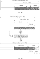
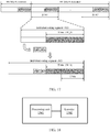
- the first part (refer to a blank part of S2 shown in FIG. 7a to FIG. 9b ) of each processed individual coding sequence S2 in the foregoing solution is not the object of focus in these implementations, and content of the first part is not limited or detailed.
- content of the first part is not limited or detailed.
- N, T, and R there are multiple possibilities for N, T, and R in the foregoing method. Therefore, according to their different conditions, specific conditions of bits in the foregoing individual coding segment may be different.
- N is less than a sum of T and R (N ⁇ T+R), and the individual coding sequence S2 further includes added bits located after the second part.
- a length of the added bits (or known as an added sequence) is a difference between the sum of T and R and N, and a length of the specific tail bit sequence is a difference between N and R.
- a white part in FIG. 7a or FIG. 7b is the foregoing first part, a grid part is a multiplex sequence, a gray part is specific tail bits, and a slashed part is an added sequence.
- N is less than a sum of T and R (N ⁇ T+R), and the specific tail bit sequence is a sequence whose length is a difference between N and R and that is at a tail of the tail bit sequence.
- FIG. 8a and FIG. 8b which are specific examples.
- a white part in FIG. 8a or FIG. 8b is the foregoing first part, a grid part is a multiplex sequence, and a gray part is specific tail bits.
- N is greater than a sum of T and R (N>T+R), the specific tail bit sequence is all bits in the tail bit sequence, and the second part further includes other bits identical to remaining bits of the identifier.
- a white part in FIG. 9a or FIG. 9b is the foregoing first part, a grid part is a multiplex sequence, and a gray part at the tail is tail bits.
- the specific tail bit sequence is specifically bits identical to normal-order high-order bits of the identifier or bits identical to reverse-order low-order bits of the identifier.
- bits of the identifier are B1, B2, B3, ..., Bn-2, Bn-1, and Bn
- the specific tail bit sequence is Bn-s, ..., Bn-2, Bn-1, and Bn (high-order bits in a normal order) or B1+s, ..., B3, B2, and B1 (low-order bits in a reverse order).
- an R-bit sequence in a protocol-defined N1 may be any sub-sequence located before a specific tail bit sequence, simply the 1 st to the R th bits in the N1, or R bits immediately preceding the specific tail bit sequence.
- the sub-sequence may alternatively be a sequence including R nonconsecutive information bits in the N1 or a sequence with an odd-numbered R-bit length. The implementations are not limited.
- the foregoing processing a to-be-encoded signaling sub-segment includes a method for processing each individual coding sequence.
- the following introduces embodiments of several possible methods for processing an individual coding sequence on a transmit side and corresponding processing methods on a receive end.
- Embodiment 1 at an AP side, 100: Determine a to-be-processed individual coding sequence (individual coding segment) S1, including a first part (a blank part of S1 in FIG. 10 ) and an identifier sequence N1. Content of the first part is not limited or detailed.
- identifier sequence N1 is at a tail of the individual coding sequence S1.
- the identifier sequence N1 is obtained according to an original AID sequence or a PAID sequence that is related to the individual coding sequence, for example, a normal-order original ID sequence N0 or a reverse-order original ID sequence N0.
- a processing procedure for the latter includes arranging the original ID sequence N0 first in a reverse order and then placing the reverse-order sequence at a tail of the sequence S1, the reverse-order sequence denoted as the sequence N1.
- 104 Perform a logical bitwise operation (for example, an XOR operation) on a protocol-defined R-bit sequence (for example, the 1 st to the R th bits, or R bits in another position) in the identifier sequence N1 and the CRC sequence R1 to obtain an R-bit multiplex sequence M1.
- a logical bitwise operation for example, an XOR operation
- R-bit sequence for example, the 1 st to the R th bits, or R bits in another position
- the tail bit sequence includes the (R+1) th to the N th bits in the identifier sequence N1 and (T+R-N) all-zero bits.
- Embodiment 1 at an STA side, 200-201: Receive a to-be-decoded sequence D0 and obtain a local ID sequence N2 according to ID information stored on a receive end.
- the local ID sequence N2 is a normal-order sequence obtained according to an original ID sequence N0 of an identifier corresponding to the receive end, or is a reverse-order sequence of the original ID sequence N0.
- the reference state sequence includes the (R+1) th to the N th bits in the local ID sequence N2 and (T+R-N) all-zero bits.
- An initial state and a final state of a shift register of a BCC decoder are set to the reference state sequence, and decoding is performed on the received individual coding segment D0 to obtain the decoded sequence D1.
- a protocol-defined sequence of an R length in the decoded sequence D1 is a multiplex sequence M2.
- the 1 st to the R th bits in (T+R) bits at the tail is the multiplex sequence M2.
- Perform a logical reverse operation for example, an XOR operation
- a protocol-defined R-bit sequence preferably the protocol-defined 1 st to R th bits of the local ID sequence N2, to obtain an R-bit CRC sequence R2.
- the sequence D2 is an information sequence required by the receive end and the receive end proceeds to other processing. Otherwise, the sequence D2 is an information sequence not required by the receive end. Generally, when the receive end does not need the information sequence, the information sequence D2 may be discarded, or the processing may be stopped.
- communication signaling overhead can be reduced; on the other hand, the entire tail bit sequence is known bits, and decoding performance is further improved.
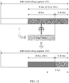
- Embodiment 2 at an AP side, 300: Determine a to-be-processed individual coding sequence (English: individual coding segment) S1, including a first part (a blank part of S1 in FIG. 12 ) and an identifier sequence N1 (a gray part of S1 in FIG. 12 ).
- a identifier sequence N1 is at a tail of the individual coding sequence S1. It should be understood that the A identifier sequence N1 may be a normal-order original ID sequence N0 or a reverse-order original ID sequence N0.
- 304 Perform a logical bitwise operation (for example, an XOR operation) on a protocol-defined R-bit sequence (preferably the protocol-defined 1 st to R th bits, or R bits in any other position) in the identifier sequence N1 and the CRC sequence R1, to obtain an R-bit multiplex sequence M1.
- a protocol-defined R-bit sequence preferably the protocol-defined 1 st to R th bits, or R bits in any other position
- Embodiment 2 at an STA side, 400-401: Receive a to-be-decoded sequence D1 and obtain an N-bit local ID sequence N2 according to ID information (for example, a PAID) stored on a receive end.
- ID information for example, a PAID
- the local ID sequence N2 is a normal-order sequence of original ID information or a reverse-order sequence of original ID information.
- the reference state sequence includes a (T+R-N)-bit random sequence and a sequence of a protocol-defined (N-R)-bit length in the local ID sequence N2 (for example, the (R+1) th to the N th bits in the local ID sequence N2).
- An initial state and a final state of a shift register of a BCC decoder are set to the reference state sequence and decoding is performed on the received individual coding segment to obtain the decoded sequence D1, where protocol-defined R bits (for example, the 1 st to the R th bits of N bits at a tail) in the sequence D1 are a multiplex sequence M2.
- the sequence D2 is an information sequence required by the receive end and the receive end proceeds to subsequent processing. Otherwise, the sequence D2 is an information sequence not required by the receive end, and the information sequence D2 may be discarded or the processing may be stopped.
- Embodiment 1 Compared with Embodiment 1, an extra tail bit sequence does not need to be added to each individual coding segment in Embodiment 2, reducing overhead in the case of a large quantity of individual coding segments. However, in comparison, because some bits in the initial and final states of the decoder are unknown, decoding performance is lower than that in Embodiment 1.
- a common part of an HE-SIG-B is used as an example.
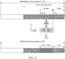
- Embodiment 3 at an AP side, it should be noted that a processing procedure in Embodiment 3 is consistent with that in Embodiment 2. Because a difference is that N is greater or equal to (T+R), the processed to-be-encoded sequence S2 may further include some bits that are not specially processed. The method includes the following steps.
- a identifier sequence N1 is at a tail of the individual coding sequence S1. It should be understood that the A identifier sequence N1 may be a normal-order original ID sequence N0 or a reverse-order original ID sequence N0.
- a logical bitwise operation for example, an XOR operation
- the protocol-defined R-bit sequence for example, a sequence of the (N-R-T+1) th to the (N-T) th bits
- the identifier sequence N1 and the CRC sequence R1 to obtain an R-bit multiplex sequence M1.
- the protocol-defined R-bit sequence in the N1 may be a more preceding sub-sequence.
- the sub-sequence may alternatively be a sequence including R nonconsecutive information bits in the N1, for example, a sequence of the 1 st to the R th bits in the identifier sequence N1 or a sequence with an odd-numbered R-bit length.
- Embodiment 3 at an STA side, 600: Receive a to-be-decoded sequence D1.
- 601 Obtain an N-bit local ID sequence N2 according to a BSSID sequence stored on a receive end.
- 604 Perform a logical reverse operation (for example, an XOR operation) on the multiplex sequence M2 and a protocol-defined R-bit sequence (for example, the (N-R-T+1) th to the (N-T) th bits) of the local ID sequence N2, to obtain an R-bit CRC sequence R2.
- a logical reverse operation for example, an XOR operation
- a protocol-defined R-bit sequence for example, the (N-R-T+1) th to the (N-T) th bits
- 608 Perform processing according to the obtained CRC sequence R2 and the reference CRC sequence R3, as well as conditions of the local ID sequence N2 and the reference sequence N3.
- the sequence D2 is an information sequence required by the receive end and the receive end proceeds to subsequent processing. Otherwise, the sequence D2 is an information sequence not required by the receive end, and the information sequence D2 may be discarded or the processing may be stopped. It should be noted that, if N is greater than (T+R) in this implementation, the reference sequence N3 may still be incorrectly decoded. Therefore, preferably, it is further considered whether the local ID sequence N2 is identical to the reference sequence N3.
- a bit-carrying ID sequence and a CRC sequence are multiplexed.
- the receive end already knows that the final state of the decoder is several bits of the ID (station ID information or ID information of a BSS that the station is in), decoding performance of an individual coding segment can be further improved.
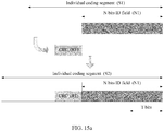
- an individual coding sequence S2 does not include multiplex bits. That is, a CRC sequence in Embodiment 4 is not multiplexed and carried on some bits in a second part but explicitly included in a first part of the individual coding sequence S2.
- the identifier sequence N1 is obtained according to an original AID or PAID sequence N0 that is related to the individual coding sequence, for example, a normal-order original AID or PAID sequence or a reverse-order original AID or PAID sequence.
- the CRC sequence R1 is located before the identifier sequence N1, and a new individual coding sequence S2 is obtained.
- the CRC sequence R1 may be located in any position before the sequence N1, for example, a position shown in FIG. 15b .
- Embodiment 4 at an STA side,
- the AID sequence N2 may be a normal-order sequence of the original AID sequence N0 or a reverse-order sequence of the original AID sequence N0.
- the initial state of the decoder is a normal-order high-order sequence or a reverse-order low-order sequence of the AID sequence N0, and a length of the sequence is T.
- sequence D2 is an information sequence required by the receive end. Otherwise, the sequence D2 may be discarded.
- reference state sequences (second parts) of individual coding segments of the sub-segment are each a segment of an ID sequence corresponding to the signaling sub-segment. These segments are included in the individual coding segments sequentially in a normal order or a reverse order.
- a common part of an HE-SIG-B is an individual coding segment
- each segment of station-based or RU-based configuration in a dedicated part of the HE-SIG-B is an individual coding segment.
- the common part of the HE-SIG-B carries the 1 st to the 6 th bits in the BSSID
- the first individual coding segment in the dedicated part of the HE-SIG-B carries the 7 th to the 12 th bits in the BSSID
- the 7 th individual coding segment in the dedicated part of the HE-SIG-B carries the 43 rd to the 48 th bits in the BSSID.
- the sequence N1_k may be removed from the N1 and placed at the tail of S1.
- the common part of the HE-SIG-B carries the 48 th to the 43 rd bits in the BSSID
- the first individual coding segment in the dedicated part of the HE-SIG-B carries the 42 nd to the 37 th bits in the BSSID
- the 7 th individual coding segment in the dedicated part of the HE-SIG-B carries the 6 th to the 1 st bits in the BSSID.
- CRC sequence R1 may be located in any position before the sequence N1_k.
- Embodiment 5 at an STA side, 1101: Receive a to-be-decoded signaling sub-segment, where the to-be-decoded signaling sub-segment includes one or more to-be-decoded sequences D0.
- a normal-order sequence or a reverse-order sequence of a BSSID sequence corresponding to the signaling sub-segment is obtained.
- sequence R2 is identical to the sequence R3, proceed to further processing of determining whether the sequence D2 is an information sequence required by the receive end. If the sequence D2 is an information sequence required by the receive end, continue the processing according to the existing rule. If the sequence D2 is an information sequence not required by the receive end, return to step 2 to continue to decode a subsequent individual coding segment. If the sequence R2 is not identical to the sequence R3, stop the processing.
- FIG. 18 another implementation provides an apparatus that is capable of processing a signaling sub-segment.
- the apparatus may be provided at an access point in a wireless local area network, including:
- the apparatus may be provided at a station in a wireless local area network, including: a processing unit (1601), configured to receive a to-be-decoded signaling sub-segment, where the to-be-decoded signaling sub-segment includes one or more to-be-decoded sequences D0; obtain a local ID sequence N2 with an N-bit length according to ID information stored on a receive end; and perform processing according to a decoding result; and a decoder (1602), configured to obtain a decoded sequence D1 for each to-be-decoded sequence D0, where an initial state and a final state of the decoder are set to a reference state sequence with a T length, and at least some bits in the reference state sequence are identical to some bits in the obtained local ID sequence N2, referred to as a specific reference state sequence in short.
- a processing unit (1601) configured to receive a to-be-decoded signaling sub-segment, where the to-be-decoded signaling
- the processing unit may be a universal processor, a digital signal processor, a dedicated integrated circuit, a field programmable gate array or another programmable logic device, a discrete gate or a transistor logic device, or a discrete hardware component.
- the processing unit may implement or execute the methods, steps, or logical schematic diagrams disclosed in the embodiments of the present invention.
- the universal processor may be a microprocessor or any conventional processor, or the like.
- the steps of the methods disclosed with reference to the embodiments of the present invention may be directly implemented by a hardware processor or by a combination of hardware and software modules in the processor. It is easily understood that the processing apparatus indicated by the foregoing resources may be at an access point when the apparatus is specifically configured to send a frame including a resource indication field; or may be at a station when the apparatus is specifically configured to receive a frame including the resource indication field.
- FIG. 19 is a schematic diagram of an access point in another embodiment of the present invention.
- the access point in FIG. 19 includes an interface 101, a processing unit 102, and a memory 103.
- the processing unit 102 controls operations of the access point 100.
- the memory 103 may include a read-only memory and a random access memory, and provides instructions and data to the processing unit 102.
- a part of the memory 103 may further include a nonvolatile random access memory (NVRAM).
- Components of the access point 100 are coupled together by using a bus system 109.
- the bus system 109 includes not only a data bus but also a power bus, a control bus, and a state signal bus. However, for clear description, all buses in the figure are marked as the bus system 109.
- the signaling processing and encoding methods disclosed in the foregoing embodiments of the present invention may be applied to the processing unit 102 or be implemented by the processing unit 102. During an implementation process, the steps of the foregoing methods may be implemented by using an integrated logic circuit of hardware in the processing unit 102, or by using software instructions.
- the processing unit 102 may be a universal processor, a digital signal processor, a dedicated integrated circuit, a field programmable gate array or another programmable logic device, a discrete gate or a transistor logic device, or a discrete hardware component.
- the processing unit 102 may implement or execute the methods, steps, or logical schematic diagrams disclosed in the embodiments of the present invention.
- the universal processor may be a microprocessor or any conventional processor, or the like.
- the steps of the methods disclosed with reference to the embodiments of the present invention may be directly implemented by a hardware processor or by a combination of hardware and software modules in the processor.
- the software module may be in a random access memory, a flash memory, a read-only memory, a programmable read-only memory or an erasable programmable memory, a register, or another mature storage medium in the art.
- the storage medium is in the memory 103, and the processing unit 102 reads information in the memory 103 and implements, in combination with its hardware, the steps of the foregoing methods.
- FIG. 20 is a schematic diagram of a station in another embodiment of the present invention.
- the access point in FIG. 20 includes an interface 111, a processing unit 112, and a memory 113.
- the processing unit 112 controls operations of the station 110.
- the memory 113 may include a read-only memory and a random access memory, and provides instructions and data to the processing unit 112.
- a part of the memory 113 may further include a nonvolatile random access memory (NVRAM).
- Components of the station 110 are coupled together by using a bus system 119.
- the bus system 119 includes not only a data bus but also a power bus, a control bus, and a state signal bus. However, for clear description, all buses in the figure are marked as the bus system 119.
- the signaling processing and decoding methods disclosed in the foregoing embodiments of the present invention may be applied to the processing unit 112 or be implemented by the processing unit 112. During an implementation process, the steps of the foregoing methods may be implemented by using an integrated logic circuit of hardware in the processing unit 112, or by using software instructions.
- the processing unit 112 may be a universal processor, a digital signal processor, a dedicated integrated circuit, a field programmable gate array or another programmable logic device, a discrete gate or a transistor logic device, or a discrete hardware component.
- the processing unit 112 may implement or execute the methods, steps, or logical schematic diagrams disclosed in the embodiments of the present invention.
- the universal processor may be a microprocessor or any conventional processor, or the like.
- the steps of the methods disclosed with reference to the embodiments of the present invention may be directly implemented by a hardware processor or by a combination of hardware and software modules in the processor.
- the software module may be in a random access memory, a flash memory, a read-only memory, a programmable read-only memory or an erasable programmable memory, a register, or another mature storage medium in the art.
- the storage medium is in the memory 113, and the processing unit 112 reads information in the memory 113 and implements, in combination with its hardware, the steps of the foregoing methods.
- the memory 113 stores instructions that make the processing unit 112 perform the following operations: determining resource status information, where the resource status information indicates a busy/idle state of a sub-resource of a channel resource for data transmission between an access point and the station; and sending the resource status information to the access point so that the access point allocates resources according to the resource status information.
- system and “network” may be used interchangeably in this specification.
- network may be used interchangeably in this specification.
- the term “and/or” in this specification describes only an association relationship for describing associated objects and represents that three relationships may exist. For example, A and/or B may represent the following three cases: Only A exists, both A and B exist, and only B exists.
- the character “/” in this specification generally indicates an “or” relationship between the associated objects.
- B corresponding to A indicates that B is associated with A, and B may be determined according to A.
- determining B according to A does not mean that B is determined according to A only; that is, B may also be determined according to A and/or other information.
- the disclosed system, apparatus, and method may be implemented in other manners.
- the described apparatus embodiments are merely examples.
- the unit division is merely logical function division and may be other division in actual implementation.
- a plurality of units or components may be combined or integrated into another system, or some features may be ignored or not performed.
- the displayed or discussed mutual couplings or direct couplings or communication connections may be implemented through some interfaces.
- the indirect couplings or communication connections between the apparatuses or units may be implemented in electronic, mechanical, or other forms.
- the units described as separate parts may or may not be physically separate, and parts displayed as units may or may not be physical units, may be located in one position, or may be distributed on a plurality of network units. A part or all of the units may be selected according to actual needs to achieve the objectives of the solutions of the embodiments of the present invention.
- functional units in the embodiments of the present invention may be integrated into one processing unit, or each of the units may exist alone physically, or two or more units are integrated into one unit.
- the integrated unit may be implemented in a form of hardware, or may be implemented in a form of a software functional unit.
- the present invention may be implemented by hardware, firmware or a combination thereof.
- the foregoing functions may be stored in a computer-readable medium or transmitted as one or more instructions or code in the computer-readable medium.
- the computer-readable medium includes a computer storage medium and a communications medium, where the communications medium includes any medium that enables a computer program to be transmitted from one place to another.
- the storage medium may be any available medium accessible to a computer.
- the computer-readable medium may include a RAM, a ROM, an EEPROM, a CD-ROM, or another optical disc storage or disk storage medium, or another magnetic storage device, or any other medium that can carry or store expected program code in a form of an instruction or a data structure and can be accessed by a computer.
- any connection may be appropriately defined as a computer-readable medium.
- the coaxial cable, optical fiber/cable, twisted pair, DSL or wireless technologies such as infrared ray, radio and microwave are included in a definition of a medium to which they belong.
- a disk (Disk) and disc (disc) used by the present invention includes a compact disc (CD), a laser disc, an optical disc, a digital versatile disc (DVD), a floppy disk and a Blu-ray disc, where the disk generally copies data by a magnetic means, and the disc copies data optically by a laser means.
Landscapes
- Engineering & Computer Science (AREA)
- Computer Networks & Wireless Communication (AREA)
- Signal Processing (AREA)
- Computing Systems (AREA)
- Physics & Mathematics (AREA)
- Probability & Statistics with Applications (AREA)
- Theoretical Computer Science (AREA)
- Mobile Radio Communication Systems (AREA)
- Error Detection And Correction (AREA)
Claims (2)
- Procédé de traitement de signalisation dans un réseau local sans fil, comprenant :le traitement d'un sous-segment de signalisation à encoder, dans lequel le sous-segment de signalisation traité comprend une ou plusieurs séquences codantes individuelles S2,dans lequel chaque séquence codante individuelle traitée S2 comprend une première partie et comprend une seconde partie avec une longueur de N bits, et la seconde partie est une séquence obtenue selon une séquence d'identifiant N1 avec une longueur de N bits, dans lequel la séquence d'identifiant N1 est liée au sous-segment de signalisation ;pour chaque séquence codante individuelle S2, l'établissement d'un état initial d'un encodeur à une séquence de bits d'extrémité avec une longueur T et la réalisation d'un encodage, dans lequel T bits au niveau d'une extrémité de la séquence codante individuelle S2 sont la séquence de bits d'extrémité, et au moins certains bits dans la séquence de bits d'extrémité sont identiques à certains bits dans la séquence d'identifiant N1, dénommée séquence de bits d'extrémité spécifique en bref (1003) ; etla seconde partie comprend en outre une séquence multiplexe avec une longueur de R bits et située avant la séquence de bits d'extrémité spécifique, dans lequel la séquence multiplexe est constituée de bits obtenus après qu'une opération au niveau du bit logique est réalisée sur R bits dans une position définie par protocole de l'identifiant et une séquence CRC avec une longueur de R bits, dans lequel la séquence CRC R1 est une séquence de contrôle de redondance cyclique obtenue selon la première partie de la séquence codante individuelle et la séquence d'identifiants N1.
- Appareil de traitement de signalisation dans un réseau local sans fil, comprenant :un processeur (1501), conçu pour traiter un sous-segment de signalisation à encoder, dans lequel le sous-segment de signalisation traité comprend une ou plusieurs séquences codantes individuelles S2, chaque séquence codante individuelle traitée S2 comprend une première partie et comprend une seconde partie avec une longueur de N bits, et la seconde partie est une séquence obtenue selon une séquence d'identifiant N1 avec une longueur de N bits, dans lequel la séquence d'identifiant N1 est liée au sous-segment de signalisation ; un encodeur (1502), conçu pour réaliser un encodage pour chaque séquence codante individuelle S2, dans lequel un état initial de l'encodeur est établi à une séquence de bits d'extrémité avec une longueur T, T bits au niveau d'une extrémité de la séquence codante individuelle S2 sont la séquence de bits d'extrémité, et au moins certains bits dans la séquence de bits d'extrémité sont identiques à certains bits dans la séquence d'identifiant N1, dénommée séquence de bits d'extrémité spécifique en bref ; etla seconde partie comprend en outre une séquence multiplexe avec une longueur de R bits et située avant la séquence de bits d'extrémité spécifique, dans lequel la séquence multiplexe est constituée de bits obtenus après qu'une opération au niveau du bit logique est réalisée sur R bits dans une position définie par protocole de l'identifiant et une séquence CRC avec une longueur de R bits, dans lequel la séquence CRC R1 est une séquence de contrôle de redondance cyclique obtenue selon la première partie de la séquence codante individuelle et la séquence d'identifiants N1.
Applications Claiming Priority (1)
| Application Number | Priority Date | Filing Date | Title |
|---|---|---|---|
| PCT/CN2015/079119 WO2016183749A1 (fr) | 2015-05-15 | 2015-05-15 | Procédé de traitement de segment de sous-signalisation, dispositif de traitement, point d'accès, et station |
Publications (3)
| Publication Number | Publication Date |
|---|---|
| EP3294020A1 EP3294020A1 (fr) | 2018-03-14 |
| EP3294020A4 EP3294020A4 (fr) | 2018-06-20 |
| EP3294020B1 true EP3294020B1 (fr) | 2020-07-29 |
Family
ID=57319101
Family Applications (1)
| Application Number | Title | Priority Date | Filing Date |
|---|---|---|---|
| EP15892128.8A Active EP3294020B1 (fr) | 2015-05-15 | 2015-05-15 | Procédé de traitement de segment de sous-signalisation, dispositif de traitement, point d'accès, et station |
Country Status (4)
| Country | Link |
|---|---|
| US (1) | US10623140B2 (fr) |
| EP (1) | EP3294020B1 (fr) |
| CN (1) | CN107615839B (fr) |
| WO (1) | WO2016183749A1 (fr) |
Families Citing this family (4)
| Publication number | Priority date | Publication date | Assignee | Title |
|---|---|---|---|---|
| DE102016118269A1 (de) * | 2016-09-27 | 2018-03-29 | Endress + Hauser Gmbh + Co. Kg | Verfahren und System zum verteilten Speichern von Informationen in einer eine Vielzahl von Feldgeräten aufweisenden Anlage der Prozessautomatisierung |
| CN110752904A (zh) * | 2018-07-24 | 2020-02-04 | 电信科学技术研究院有限公司 | 一种信息传输方法、终端及基站 |
| WO2022238286A1 (fr) * | 2021-05-10 | 2022-11-17 | Nordic Semiconductor Asa | Procédé de transmission |
| US20250392963A1 (en) * | 2024-06-20 | 2025-12-25 | Avago Technologies International Sales Pte. Limited | Marker sequences for extended long range wireless communications |
Family Cites Families (10)
| Publication number | Priority date | Publication date | Assignee | Title |
|---|---|---|---|---|
| US7945052B2 (en) | 2007-03-29 | 2011-05-17 | Gary Stephen Shuster | Method of distributing a decryption key in fixed-content data |
| JP4922242B2 (ja) * | 2008-06-05 | 2012-04-25 | パナソニック株式会社 | 符号化装置、符号化方法、及びビタビ復号装置 |
| CN102142848B (zh) * | 2010-01-28 | 2014-03-12 | 中兴通讯股份有限公司 | 一种咬尾卷积码的译码方法及译码器 |
| KR20110124729A (ko) * | 2010-05-11 | 2011-11-17 | 한국전자통신연구원 | 통신 시스템에서 데이터 송수신 장치 및 방법 |
| AU2012295079B2 (en) * | 2011-08-07 | 2015-09-17 | Lg Electronics Inc. | Method and apparatus for transmitting and receiving frame on the basis of frequency selection transmission |
| KR101558112B1 (ko) | 2011-08-07 | 2015-10-06 | 엘지전자 주식회사 | 무선랜 시스템에서 채널 액세스 방법 및 장치 |
| CN103001729B (zh) * | 2011-09-14 | 2016-06-08 | 华为技术有限公司 | 一种编码调制方法以及相关装置 |
| CN105009540B (zh) * | 2013-12-31 | 2018-06-19 | 华为技术有限公司 | 一种加扰方法及加扰装置 |
| EP3136673B1 (fr) * | 2014-05-16 | 2019-08-28 | Huawei Technologies Co. Ltd. | Procédé et dispositif de conception de trame agrégée |
| US9712848B2 (en) * | 2014-11-10 | 2017-07-18 | Vixs Systems Inc. | Frame buffer compression using separate aggregation of fixed-length and variable-length components of codewords |
-
2015
- 2015-05-15 CN CN201580080034.9A patent/CN107615839B/zh active Active
- 2015-05-15 EP EP15892128.8A patent/EP3294020B1/fr active Active
- 2015-05-15 WO PCT/CN2015/079119 patent/WO2016183749A1/fr not_active Ceased
-
2017
- 2017-11-14 US US15/812,903 patent/US10623140B2/en active Active
Non-Patent Citations (1)
| Title |
|---|
| None * |
Also Published As
| Publication number | Publication date |
|---|---|
| US20180069659A1 (en) | 2018-03-08 |
| US10623140B2 (en) | 2020-04-14 |
| EP3294020A4 (fr) | 2018-06-20 |
| CN107615839A (zh) | 2018-01-19 |
| CN107615839B (zh) | 2020-03-31 |
| EP3294020A1 (fr) | 2018-03-14 |
| WO2016183749A1 (fr) | 2016-11-24 |
Similar Documents
| Publication | Publication Date | Title |
|---|---|---|
| CN108347302B (zh) | 一种编译码方法和终端 | |
| CN110324115B (zh) | 一种数据传输方法、装置、存储介质及终端设备 | |
| EP3614589B1 (fr) | Procédé de transmission d'informations, procédé et dispositif de décodage | |
| CN109391347B (zh) | 编译码方法及装置 | |
| US12132569B2 (en) | Method for sidelink rate matching and resource mapping, and device | |
| US20190207709A1 (en) | Communication method and apparatus | |
| US10623140B2 (en) | Method for processing signaling sub-segment, processing apparatus, access point, and station | |
| EP3567766A1 (fr) | Procédé et appareil de transmission de données | |
| WO2019024594A1 (fr) | Procédés, appareils et dispositifs permettant de coder et décoder un code de polarisation | |
| JP2019534656A (ja) | 符号化及び復号方法並びにデバイス | |
| CN110635867B (zh) | 通信方法、网络设备和终端 | |
| US20200007164A1 (en) | Coding method, decoding method, apparatus, and device | |
| WO2017124844A1 (fr) | Procédé de détermination de taille de bloc de transmission d'un code de polarisation, et dispositif de communication | |
| CN110391874B (zh) | 极化码的速率匹配、解速率匹配方法及设备 | |
| WO2018098691A1 (fr) | Procédé de génération de canal de commande, procédé de détection de canal de commande et appareil associé | |
| CN112738889B (zh) | 一种频域资源的指示方法及设备 | |
| CN108631923B (zh) | 传输信息的方法、网络设备和终端设备 | |
| CN115276886A (zh) | 一种编码识别方法及装置 | |
| CN103457611A (zh) | 用于执行信道编译型控的方法及装置 | |
| WO2018202151A1 (fr) | Procédé et dispositif de communication | |
| RU2674253C1 (ru) | Способ приема и способ отправки информации по каналу нисходящей линии связи, устройство пользователя и сетевое устройство | |
| US12143125B2 (en) | Polarization encoding method and apparatus | |
| CN114339656B (zh) | 辅链路资源处理方法及装置 | |
| CN108365911B (zh) | 一种信息的编码方法及设备 | |
| US11362677B2 (en) | Channel encoding method and encoding apparatus |
Legal Events
| Date | Code | Title | Description |
|---|---|---|---|
| STAA | Information on the status of an ep patent application or granted ep patent |
Free format text: STATUS: THE INTERNATIONAL PUBLICATION HAS BEEN MADE |
|
| PUAI | Public reference made under article 153(3) epc to a published international application that has entered the european phase |
Free format text: ORIGINAL CODE: 0009012 |
|
| STAA | Information on the status of an ep patent application or granted ep patent |
Free format text: STATUS: REQUEST FOR EXAMINATION WAS MADE |
|
| 17P | Request for examination filed |
Effective date: 20171127 |
|
| AK | Designated contracting states |
Kind code of ref document: A1 Designated state(s): AL AT BE BG CH CY CZ DE DK EE ES FI FR GB GR HR HU IE IS IT LI LT LU LV MC MK MT NL NO PL PT RO RS SE SI SK SM TR |
|
| AX | Request for extension of the european patent |
Extension state: BA ME |
|
| A4 | Supplementary search report drawn up and despatched |
Effective date: 20180523 |
|
| RIC1 | Information provided on ipc code assigned before grant |
Ipc: H04W 72/00 20090101AFI20180516BHEP Ipc: H04L 1/00 20060101ALI20180516BHEP |
|
| DAV | Request for validation of the european patent (deleted) | ||
| DAX | Request for extension of the european patent (deleted) | ||
| STAA | Information on the status of an ep patent application or granted ep patent |
Free format text: STATUS: EXAMINATION IS IN PROGRESS |
|
| 17Q | First examination report despatched |
Effective date: 20181214 |
|
| GRAP | Despatch of communication of intention to grant a patent |
Free format text: ORIGINAL CODE: EPIDOSNIGR1 |
|
| STAA | Information on the status of an ep patent application or granted ep patent |
Free format text: STATUS: GRANT OF PATENT IS INTENDED |
|
| INTG | Intention to grant announced |
Effective date: 20200331 |
|
| GRAS | Grant fee paid |
Free format text: ORIGINAL CODE: EPIDOSNIGR3 |
|
| GRAA | (expected) grant |
Free format text: ORIGINAL CODE: 0009210 |
|
| STAA | Information on the status of an ep patent application or granted ep patent |
Free format text: STATUS: THE PATENT HAS BEEN GRANTED |
|
| AK | Designated contracting states |
Kind code of ref document: B1 Designated state(s): AL AT BE BG CH CY CZ DE DK EE ES FI FR GB GR HR HU IE IS IT LI LT LU LV MC MK MT NL NO PL PT RO RS SE SI SK SM TR |
|
| REG | Reference to a national code |
Ref country code: CH Ref legal event code: EP |
|
| REG | Reference to a national code |
Ref country code: AT Ref legal event code: REF Ref document number: 1297311 Country of ref document: AT Kind code of ref document: T Effective date: 20200815 |
|
| REG | Reference to a national code |
Ref country code: IE Ref legal event code: FG4D |
|
| REG | Reference to a national code |
Ref country code: DE Ref legal event code: R096 Ref document number: 602015056723 Country of ref document: DE |
|
| REG | Reference to a national code |
Ref country code: LT Ref legal event code: MG4D |
|
| REG | Reference to a national code |
Ref country code: NL Ref legal event code: MP Effective date: 20200729 |
|
| REG | Reference to a national code |
Ref country code: AT Ref legal event code: MK05 Ref document number: 1297311 Country of ref document: AT Kind code of ref document: T Effective date: 20200729 |
|
| PG25 | Lapsed in a contracting state [announced via postgrant information from national office to epo] |
Ref country code: ES Free format text: LAPSE BECAUSE OF FAILURE TO SUBMIT A TRANSLATION OF THE DESCRIPTION OR TO PAY THE FEE WITHIN THE PRESCRIBED TIME-LIMIT Effective date: 20200729 Ref country code: BG Free format text: LAPSE BECAUSE OF FAILURE TO SUBMIT A TRANSLATION OF THE DESCRIPTION OR TO PAY THE FEE WITHIN THE PRESCRIBED TIME-LIMIT Effective date: 20201029 Ref country code: SE Free format text: LAPSE BECAUSE OF FAILURE TO SUBMIT A TRANSLATION OF THE DESCRIPTION OR TO PAY THE FEE WITHIN THE PRESCRIBED TIME-LIMIT Effective date: 20200729 Ref country code: HR Free format text: LAPSE BECAUSE OF FAILURE TO SUBMIT A TRANSLATION OF THE DESCRIPTION OR TO PAY THE FEE WITHIN THE PRESCRIBED TIME-LIMIT Effective date: 20200729 Ref country code: LT Free format text: LAPSE BECAUSE OF FAILURE TO SUBMIT A TRANSLATION OF THE DESCRIPTION OR TO PAY THE FEE WITHIN THE PRESCRIBED TIME-LIMIT Effective date: 20200729 Ref country code: GR Free format text: LAPSE BECAUSE OF FAILURE TO SUBMIT A TRANSLATION OF THE DESCRIPTION OR TO PAY THE FEE WITHIN THE PRESCRIBED TIME-LIMIT Effective date: 20201030 Ref country code: FI Free format text: LAPSE BECAUSE OF FAILURE TO SUBMIT A TRANSLATION OF THE DESCRIPTION OR TO PAY THE FEE WITHIN THE PRESCRIBED TIME-LIMIT Effective date: 20200729 Ref country code: PT Free format text: LAPSE BECAUSE OF FAILURE TO SUBMIT A TRANSLATION OF THE DESCRIPTION OR TO PAY THE FEE WITHIN THE PRESCRIBED TIME-LIMIT Effective date: 20201130 Ref country code: AT Free format text: LAPSE BECAUSE OF FAILURE TO SUBMIT A TRANSLATION OF THE DESCRIPTION OR TO PAY THE FEE WITHIN THE PRESCRIBED TIME-LIMIT Effective date: 20200729 Ref country code: NO Free format text: LAPSE BECAUSE OF FAILURE TO SUBMIT A TRANSLATION OF THE DESCRIPTION OR TO PAY THE FEE WITHIN THE PRESCRIBED TIME-LIMIT Effective date: 20201029 |
|
| PG25 | Lapsed in a contracting state [announced via postgrant information from national office to epo] |
Ref country code: RS Free format text: LAPSE BECAUSE OF FAILURE TO SUBMIT A TRANSLATION OF THE DESCRIPTION OR TO PAY THE FEE WITHIN THE PRESCRIBED TIME-LIMIT Effective date: 20200729 Ref country code: LV Free format text: LAPSE BECAUSE OF FAILURE TO SUBMIT A TRANSLATION OF THE DESCRIPTION OR TO PAY THE FEE WITHIN THE PRESCRIBED TIME-LIMIT Effective date: 20200729 Ref country code: PL Free format text: LAPSE BECAUSE OF FAILURE TO SUBMIT A TRANSLATION OF THE DESCRIPTION OR TO PAY THE FEE WITHIN THE PRESCRIBED TIME-LIMIT Effective date: 20200729 Ref country code: IS Free format text: LAPSE BECAUSE OF FAILURE TO SUBMIT A TRANSLATION OF THE DESCRIPTION OR TO PAY THE FEE WITHIN THE PRESCRIBED TIME-LIMIT Effective date: 20201129 |
|
| PG25 | Lapsed in a contracting state [announced via postgrant information from national office to epo] |
Ref country code: NL Free format text: LAPSE BECAUSE OF FAILURE TO SUBMIT A TRANSLATION OF THE DESCRIPTION OR TO PAY THE FEE WITHIN THE PRESCRIBED TIME-LIMIT Effective date: 20200729 |
|
| PG25 | Lapsed in a contracting state [announced via postgrant information from national office to epo] |
Ref country code: EE Free format text: LAPSE BECAUSE OF FAILURE TO SUBMIT A TRANSLATION OF THE DESCRIPTION OR TO PAY THE FEE WITHIN THE PRESCRIBED TIME-LIMIT Effective date: 20200729 Ref country code: SM Free format text: LAPSE BECAUSE OF FAILURE TO SUBMIT A TRANSLATION OF THE DESCRIPTION OR TO PAY THE FEE WITHIN THE PRESCRIBED TIME-LIMIT Effective date: 20200729 Ref country code: RO Free format text: LAPSE BECAUSE OF FAILURE TO SUBMIT A TRANSLATION OF THE DESCRIPTION OR TO PAY THE FEE WITHIN THE PRESCRIBED TIME-LIMIT Effective date: 20200729 Ref country code: IT Free format text: LAPSE BECAUSE OF FAILURE TO SUBMIT A TRANSLATION OF THE DESCRIPTION OR TO PAY THE FEE WITHIN THE PRESCRIBED TIME-LIMIT Effective date: 20200729 Ref country code: DK Free format text: LAPSE BECAUSE OF FAILURE TO SUBMIT A TRANSLATION OF THE DESCRIPTION OR TO PAY THE FEE WITHIN THE PRESCRIBED TIME-LIMIT Effective date: 20200729 Ref country code: CZ Free format text: LAPSE BECAUSE OF FAILURE TO SUBMIT A TRANSLATION OF THE DESCRIPTION OR TO PAY THE FEE WITHIN THE PRESCRIBED TIME-LIMIT Effective date: 20200729 |
|
| REG | Reference to a national code |
Ref country code: DE Ref legal event code: R097 Ref document number: 602015056723 Country of ref document: DE |
|
| PG25 | Lapsed in a contracting state [announced via postgrant information from national office to epo] |
Ref country code: AL Free format text: LAPSE BECAUSE OF FAILURE TO SUBMIT A TRANSLATION OF THE DESCRIPTION OR TO PAY THE FEE WITHIN THE PRESCRIBED TIME-LIMIT Effective date: 20200729 |
|
| PLBE | No opposition filed within time limit |
Free format text: ORIGINAL CODE: 0009261 |
|
| STAA | Information on the status of an ep patent application or granted ep patent |
Free format text: STATUS: NO OPPOSITION FILED WITHIN TIME LIMIT |
|
| PG25 | Lapsed in a contracting state [announced via postgrant information from national office to epo] |
Ref country code: SK Free format text: LAPSE BECAUSE OF FAILURE TO SUBMIT A TRANSLATION OF THE DESCRIPTION OR TO PAY THE FEE WITHIN THE PRESCRIBED TIME-LIMIT Effective date: 20200729 |
|
| 26N | No opposition filed |
Effective date: 20210430 |
|
| PG25 | Lapsed in a contracting state [announced via postgrant information from national office to epo] |
Ref country code: SI Free format text: LAPSE BECAUSE OF FAILURE TO SUBMIT A TRANSLATION OF THE DESCRIPTION OR TO PAY THE FEE WITHIN THE PRESCRIBED TIME-LIMIT Effective date: 20200729 |
|
| REG | Reference to a national code |
Ref country code: CH Ref legal event code: PL |
|
| GBPC | Gb: european patent ceased through non-payment of renewal fee |
Effective date: 20210515 |
|
| PG25 | Lapsed in a contracting state [announced via postgrant information from national office to epo] |
Ref country code: MC Free format text: LAPSE BECAUSE OF FAILURE TO SUBMIT A TRANSLATION OF THE DESCRIPTION OR TO PAY THE FEE WITHIN THE PRESCRIBED TIME-LIMIT Effective date: 20200729 Ref country code: LU Free format text: LAPSE BECAUSE OF NON-PAYMENT OF DUE FEES Effective date: 20210515 Ref country code: LI Free format text: LAPSE BECAUSE OF NON-PAYMENT OF DUE FEES Effective date: 20210531 Ref country code: CH Free format text: LAPSE BECAUSE OF NON-PAYMENT OF DUE FEES Effective date: 20210531 |
|
| REG | Reference to a national code |
Ref country code: BE Ref legal event code: MM Effective date: 20210531 |
|
| PG25 | Lapsed in a contracting state [announced via postgrant information from national office to epo] |
Ref country code: IE Free format text: LAPSE BECAUSE OF NON-PAYMENT OF DUE FEES Effective date: 20210515 Ref country code: GB Free format text: LAPSE BECAUSE OF NON-PAYMENT OF DUE FEES Effective date: 20210515 |
|
| PG25 | Lapsed in a contracting state [announced via postgrant information from national office to epo] |
Ref country code: FR Free format text: LAPSE BECAUSE OF NON-PAYMENT OF DUE FEES Effective date: 20210531 |
|
| PG25 | Lapsed in a contracting state [announced via postgrant information from national office to epo] |
Ref country code: BE Free format text: LAPSE BECAUSE OF NON-PAYMENT OF DUE FEES Effective date: 20210531 |
|
| PG25 | Lapsed in a contracting state [announced via postgrant information from national office to epo] |
Ref country code: HU Free format text: LAPSE BECAUSE OF FAILURE TO SUBMIT A TRANSLATION OF THE DESCRIPTION OR TO PAY THE FEE WITHIN THE PRESCRIBED TIME-LIMIT; INVALID AB INITIO Effective date: 20150515 |
|
| PG25 | Lapsed in a contracting state [announced via postgrant information from national office to epo] |
Ref country code: CY Free format text: LAPSE BECAUSE OF FAILURE TO SUBMIT A TRANSLATION OF THE DESCRIPTION OR TO PAY THE FEE WITHIN THE PRESCRIBED TIME-LIMIT Effective date: 20200729 |
|
| PG25 | Lapsed in a contracting state [announced via postgrant information from national office to epo] |
Ref country code: MK Free format text: LAPSE BECAUSE OF FAILURE TO SUBMIT A TRANSLATION OF THE DESCRIPTION OR TO PAY THE FEE WITHIN THE PRESCRIBED TIME-LIMIT Effective date: 20200729 |
|
| PG25 | Lapsed in a contracting state [announced via postgrant information from national office to epo] |
Ref country code: MT Free format text: LAPSE BECAUSE OF FAILURE TO SUBMIT A TRANSLATION OF THE DESCRIPTION OR TO PAY THE FEE WITHIN THE PRESCRIBED TIME-LIMIT Effective date: 20200729 |
|
| PGFP | Annual fee paid to national office [announced via postgrant information from national office to epo] |
Ref country code: DE Payment date: 20250402 Year of fee payment: 11 |
|
| PG25 | Lapsed in a contracting state [announced via postgrant information from national office to epo] |
Ref country code: TR Free format text: LAPSE BECAUSE OF FAILURE TO SUBMIT A TRANSLATION OF THE DESCRIPTION OR TO PAY THE FEE WITHIN THE PRESCRIBED TIME-LIMIT Effective date: 20200729 |