EP3294089B1 - Bürstenkopfanordnungen - Google Patents
Bürstenkopfanordnungen Download PDFInfo
- Publication number
- EP3294089B1 EP3294089B1 EP16724117.3A EP16724117A EP3294089B1 EP 3294089 B1 EP3294089 B1 EP 3294089B1 EP 16724117 A EP16724117 A EP 16724117A EP 3294089 B1 EP3294089 B1 EP 3294089B1
- Authority
- EP
- European Patent Office
- Prior art keywords
- retention
- brush head
- brush
- bristle
- proximal end
- Prior art date
- Legal status (The legal status is an assumption and is not a legal conclusion. Google has not performed a legal analysis and makes no representation as to the accuracy of the status listed.)
- Active
Links
Images



Classifications
-
- A—HUMAN NECESSITIES
- A46—BRUSHWARE
- A46B—BRUSHES
- A46B3/00—Brushes characterised by the way in which the bristles are fixed or joined in or on the brush body or carrier
- A46B3/08—Brushes characterised by the way in which the bristles are fixed or joined in or on the brush body or carrier by clamping
- A46B3/10—Brushes characterised by the way in which the bristles are fixed or joined in or on the brush body or carrier by clamping into rings or the like
-
- A—HUMAN NECESSITIES
- A46—BRUSHWARE
- A46B—BRUSHES
- A46B3/00—Brushes characterised by the way in which the bristles are fixed or joined in or on the brush body or carrier
- A46B3/06—Brushes characterised by the way in which the bristles are fixed or joined in or on the brush body or carrier by welding together bristles made of metal wires or plastic materials
-
- A—HUMAN NECESSITIES
- A46—BRUSHWARE
- A46B—BRUSHES
- A46B3/00—Brushes characterised by the way in which the bristles are fixed or joined in or on the brush body or carrier
- A46B3/20—Brushes characterised by the way in which the bristles are fixed or joined in or on the brush body or carrier the bristles being fixed or joined in rubber bodies, e.g. in soft rubber
-
- A—HUMAN NECESSITIES
- A46—BRUSHWARE
- A46D—MANUFACTURE OF BRUSHES
- A46D3/00—Preparing, i.e. Manufacturing brush bodies
- A46D3/04—Machines for inserting or fixing bristles in bodies
- A46D3/045—Machines for inserting or fixing bristles in bodies for fixing bristles by fusing or gluing to a body
-
- A—HUMAN NECESSITIES
- A46—BRUSHWARE
- A46B—BRUSHES
- A46B2200/00—Brushes characterized by their functions, uses or applications
- A46B2200/10—For human or animal care
- A46B2200/1066—Toothbrush for cleaning the teeth or dentures
-
- A—HUMAN NECESSITIES
- A46—BRUSHWARE
- A46B—BRUSHES
- A46B9/00—Arrangements of the bristles in the brush body
- A46B9/02—Position or arrangement of bristles in relation to surface of the brush body, e.g. inclined, in rows, in groups
- A46B9/04—Arranged like in or for toothbrushes
Definitions
- the present disclosure is directed generally to a brush head assembly with a plurality of bristle tufts, and more particularly, to the arrangement, structure, and securement of bristle tufts in the brush head assembly.
- US 2008/168613 A1 discloses a brush head, in particular a toothbrush, with a base carrier formed from a soft elastic material in which connecting elements comprising separate support rings separated from one another and bearing a plurality of bristle tufts are embedded, each of the rings having a bristle tuft threaded through.
- the bristle tuft can move axially in the support ring and is supported resiliently by the soft elastic material.
- US 2012/233790 A1 discloses a brush body having bristle bundles embedded in a brush head.
- a bristle contained in the bristle bundles includes a core which consists of a conductive member, and a sheath which consists of an insulating member and covers the core.
- the core is exposed at the tip portion of the bristle and functions as an electrode for passing current into the mouth.
- the embedding of the bristle bundles in an electrically conductive base arranged in the brush head electrically connects the core to the base.
- WO 2004/080238 A1 discloses a method and a device for producing a brush, in particular a toothbrush comprising a brush head that has a bundle of bristles.
- a large number of retaining elements are formed in a first injection mould; the bundle of bristles are inserted into the individual retaining elements; the retaining elements are arranged on a perforated plate that complements a mould half of the second injection mould, and said perforated plate is placed into the mould half of the second injection mould in order to complete said second injection mould; the second injection mould, into which a pre-fabricated brush base body has been inserted, is closed; the bundle of bristles is permanently connected to the brush base body by the injection of a soft elastic plastic component; and the resultant brush is removed from the second injection mould.
- the device comprises a first injection mould for forming the retaining elements, in addition to a second injection mould for forming the soft elastic mat.
- One mould half of said second injection mould has retaining channels for receiving the bundle of bristles in addition to retaining elements associated with the retaining channels for securing a respective retaining element in the vicinity of the retaining channels.
- the other mould half of the injection mould forms a cavity, which is proportioned in such a way that a prefabricated brush head, having at least one recess that defines the peripheral surface of the mat cavity for forming the mat, can be accommodated in the closed second injection mould.
- Periodontal diseases are thought to be infectious diseases caused by bacteria present in dental plaques. Tooth brushing is a highly effective method to remove dental plaque from the teeth. Power toothbrushes can enhance the removal of dental plaque. Such power toothbrushes have a set of bristles attached to a brush head which is moved by a driver that causes the bristles to scrub dental surfaces.
- the brush heads of both manual and power toothbrushes comprise bristles which are used to clean the teeth, tongue, and cheeks.
- the bristles are organized into bristle tufts contained within retention rings.
- the retention rings serve to secure the bristle tufts within the brush head and often have a hollow circular shape with an interior and exterior circular circumference.
- the bristle tufts are inserted into the hollow interior of the retention ring, and the bristles in the retention ring are then secured into a brush head material which is then cooled or allowed to cool in order to form the final brush head.
- the retention rings are not firmly secured within the brush head.
- the ring and bristle tuft can be or become loose within the brush head, and the bristles might not always be positioned at an angle optimal for brushing.
- the bristle tuft structure can undergo higher stresses under the dynamic motion, which could lead to separation.
- the process of organizing the bristles into tufts within the retention rings and then cooling the brush head material, or allowing it to cool, in order to fix the tufts in place can be time-consuming and expensive.
- the present disclosure is directed to inventive methods for a brush head assembly with secured bristle tufts.
- Various embodiments and implementations herein are directed to brush head assemblies in which bristle tufts are affixed with retention rings and are then embedded within an elastomeric matrix resulting in a completed brush head.
- retention of bristle tufts within brush heads is substantially improved.
- the exterior wall of a retention ring can include a transverse projection to provide better adhesion of the retention ring in the elastomeric matrix.
- the main pull out mechanism of the tuft typically occurs with delamination in the elastomeric matrix-retention ring bond, so increasing the surface area can be critical to improved retention.
- the proximal end head portion of two or more of the bristle tufts can be joined together to improve retention.
- the present disclosure describes various embodiments of a brush head assembly with bristle tufts retained within retention rings within an elastomeric matrix. More generally, Applicants have recognized and appreciated that it would be beneficial to provide a brush head formed with bristles embedded in an elastomeric matrix in order to improve bristle retention. Providing a retention ring with one or more transverse projections results in better adhesion of the retention ring within the elastomeric matrix. Additionally, joining together the proximal end head portion of two or more of the bristle tufts improves retention of the bristle tufts within the brush head assembly, especially in powered toothbrush devices. A particular goal of utilization of certain embodiments of the present disclosure is the ability to create brush head assemblies in which bristle tufts are more efficiently retained within the brush head.
- the brush heads disclosed and described herein can be used with any manual or power toothbrush device.
- a power toothbrush device that the brush head can be used with Sonicare ® devices available from Koninklijke Philips Electronics N.V.
- Sonicare ® devices available from Koninklijke Philips Electronics N.V.
- This oral care device is based upon an actuator with a reciprocating brush head including bristles to provide an effective cleaning of a user's teeth.
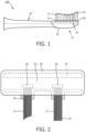
- a schematic representation of a brush head assembly 100 is provided.
- the brush head assembly includes a neck 40, which can be coupled to any manual brush shaft, or, more preferably, to any actuator and drive shaft (not shown) made or suitable for oral care devices now known or to be developed.
- the brush head 32 of the brush head assembly includes a plurality of bristle tufts 21, each of which comprises a plurality of bristle strands.
- the bristle tufts are composed of nylon, or another suitable material, and optionally can be coated with polyurethane, polybutylene terephthalate (PBT), polyolefin, combinations of these, or a similar polymer.
- PBT polybutylene terephthalate
- Each bristle tuft includes a proximal end 23 and a free end 25, where the proximal end of each bristle tuft is retained within the brush head assembly 100.
- Each bristle tuft 21 is retained within a respective one of a plurality of retention rings 50.
- the proximal end of the bristle tuft and the retention rings and the supporting portion 42 of the brush neck 40 are retained within a flexible elastomeric matrix 30 to form a head portion 32 of the brush head assembly 100.
- the elastomeric matrix 30 is preferably made from a flexible thermoplastic elastomer (TPE), and the retention rings are preferably made from thermoplastic polymer such as polypropylene.
- TPE flexible thermoplastic elastomer
- the retention rings are preferably made from thermoplastic polymer such as polypropylene.
- Each of the brush neck 40, supporting portion of the brush neck 42, and the retention rings 50 is preferably made from a material with a higher elastic modulus value than the elastomeric matrix
- each of the bristle tufts 21 is surrounded by a retaining ring 50, or a portion of a retaining ring 50, and each has a free end 25 and a proximal end 23 with a head portion 26.
- a plurality of retention rings 50 is provided.
- Retention rings 50 can be of a plurality of shapes, sizes, configurations or tapers.
- the retention rings 50 can optionally be connected or at least partially interconnected by a webbing or network of webbing links 91 to improve retention ring and bristle tuft retention within the brush head (as shown in FIG.
- retaining rings 50 shown in the figures herein are shown as straight cylinders for the sake of simplicity, they can be a variety of different shapes both inside and outside (pentagons, squares, etc.) and have various tapers or partial tapers to the inside and outside of the retaining rings, and retaining rings of various shapes can be used together in a single brush head.
- elastomeric material is formed around the supporting portion of the brush neck 42, the proximal end head portion 26 of the bristle tufts 21, all or a portion of the retaining rings 50, as well as the webbing links 91 if they are present.
- the elastomeric material forms an elastomeric matrix 30 that fills in the space 92 between the supporting portion of the brush neck 42 and the proximal end head portion 26.
- elastomeric matrix 30 is preferably made from a flexible thermoplastic elastomer, while the retaining rings are preferably made from thermoplastic polymer such as polypropylene.
- each of the brush neck 40 and the retaining rings 50 is made from a material with a higher elastic modulus than the elastomeric matrix 30.
- This additional layer of elastomeric matrix between the retaining head and the tuft ring can be compressed during operation, such that when the bristle tuft is being pulled downward toward the free end of the bristles the matrix absorbs some of the pressure, and the force is distributed throughout the elastomeric matrix. This results in greater flexibility of tuft movement, and also, by reducing the pressure, reduces the probability of the retaining head breaking through the retaining ring.
- FIG. 3 is a cutaway side view of a prior art bristle tuft 21' with a retention ring 50'.
- the bristle tuft 21' is inserted into and surrounded by a retaining ring 50', or a portion of a retaining ring 50'.
- the retaining ring 50' has a cylindrical straight interior wall and a straight exterior wall without any transverse projections on either the interior wall or the exterior wall.
- the proximal end head portion 26' of the bristle tuft 21' is retained with an elastomeric matrix 30', and also helps prevent the bristle tuft from being pulled out of the elastomeric matrix and retaining ring. However, with moderate force the bristle tuft can still be pulled from the elastomeric matrix and retaining ring, resulting in bristle tuft loss.
- FIG. 4 in one embodiment, is a cutaway side view of a bristle tuft 21 in a retention ring 50 and comprising a proximal end head portion 26, embedded in an elastomeric matrix 30.
- the retention ring 50 comprises an upper portion 51, a lower portion 53, and an exterior wall 57.
- the exterior wall 57 of the retention ring 50 comprises at least one transverse projection 71 extending outwardly therefrom.
- the transverse projection 71 can take many different forms and configurations. Referring to FIG. 4 , for example, transverse projection 71 is an angled projection that points upward, while transverse projection 71 is an angled projection that points downward.
- transverse projections can be positioned anywhere along the retention ring, including nearer to the upper portion 51, near to the lower portion 53, equidistant between the lower and upper portions, and a combination of all three positions. As shown in FIG. 4 , for example, the transverse projections 71 provide better adherence of the retention ring in the elastomeric matrix 30. It would require greater force, for example, to pull the retention ring from the elastomeric matrix due to the one or more transverse projections 71.
- FIG. 5 in one embodiment, is a cutaway side view of a bristle tuft 21 in a retention ring 50 and comprising a proximal end head portion 26, embedded in an elastomeric matrix 30.
- the exterior wall 57 of the retention ring 50 comprises several transverse projections 71 located at several different locations along the wall. These transverse projections are embedded in the elastomeric matrix 30 and help prevent loss of the retention ring and/or bristle tuft from the elastomeric matrix.
- a transverse projection 71 of the retention ring comprises a screw-thread like helical projection projecting outwards along the length of the exterior wall 57 from the upper portion 51 to the lower portion 53.
- each transverse projection (or each length of the transverse projection) comprises a projection 71 from the exterior wall 57 of the retention ring, and a projection 72 from the interior wall 55 of the retention ring.
- the transverse projection wraps around the entire wall of the retention ring, with a portion 71 projecting outward from the retention ring's central longitudinal axis, and a portion 72 projecting inward toward the retention rings central longitudinal axis.
- This embodiment interacts with both the bristle tuft 21 and the elastomeric matrix 30 when the brush head is assembled.
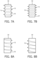
- the retention ring 50 has a transverse projection 72 on only the interior wall 55 thereof for improved securement of the bristle tuft 21 (not shown) in the retention ring 50.
- the internal transverse projection 72 in FIGS. 7A through 8B could facilitate bristle retention in a brush configuration in which the bristles are made of a softer material with a high coefficient of friction, such as a compressible rubber, and the tuft ring material is made of a harder material with a rough surface.
- the interior transverse projection 72 would act like a collet or collar to grip or hold onto the bristles.
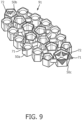
- FIG. 9 is a schematic representation of an optional webbing network 91 of retention rings 50 (50a, 50b, 50c, ).
- One or more of the retention rings in the network comprise one or more of the following: transverse projection(s) 71 extending outwardly from the exterior wall of the retention ring, transverse projection(s) 72 extending inwardly from the interior wall of the retention ring, and/or both transverse projection(s) 71 and transverse projection(s) 72.
- transverse projection(s) 71 extending outwardly from the exterior wall of the retention ring
- transverse projection(s) 72 extending inwardly from the interior wall of the retention ring
- transverse projection(s) 72 extending inwardly from the interior wall of the retention ring
- the retention rings might be shown as straight, cylindrical shapes for the purposes of simplicity, it should be appreciated that the retaining rings can have varying interior and exterior shapes (including but not limited to circular, square, hexagonal, and many others), and one or more of the interior or exterior of the retaining rings can be tapered in varying directions and angles, the same or different ways, along part of all of the length of the retaining rings.
- brush head 32 is a flowchart depicted a method 200 for manufacturing a brush head 32.
- the brush head can be any of the brush heads described or otherwise envisioned herein.
- brush head 32 can comprise a plurality of bristle tufts 21, each retained within a retention ring 50, where the proximal end of each bristle tuft is retained within a flexible elastomeric matrix 30 to form a head portion 32 of the brush head assembly 100.
- a plurality of retention rings 50 is provided.
- the retention rings can be made from thermoplastic polymer such as polypropylene.
- the retention rings 50 ban be made from a material with a higher elastic modulus value than, for example, the elastomeric matrix 30.
- the retention rings can be of a plurality of shapes, sizes, configurations, or tapers.
- the retention rings are connected or at least partially interconnected by a webbing network 91 of retention rings to improve retention ring and bristle tuft retention within the brush head.
- one or more of the retaining rings 50 in the brush head 32 comprise one or more transverse projections 71 extending inwardly from the interior wall of the retention ring to engage the elastomeric matrix 30, and/or one or more transverse projections 72 extending inwardly from the interior wall of the retention ring to engage the bristle tuft 21.
- a plurality of bristle tufts 21 each comprising a plurality of bristle strands is provided.
- Each bristle tuft includes a proximal end 23 and a free end 25, where the proximal end of each bristle tuft is retained within the brush head assembly 100.
- each of the plurality of bristle tufts 21 is inserted into a respective one of the plurality of retention rings 50.
- This can be, for example, an automated process in which bristle tufts are sequentially inserted into the retention rings, are inserted into the retention rings in a random order, or are simultaneously inserted into the retention rings.
- the bristles of the bristle tufts may be inserted to comprise different heights and different angles, and can vary among a single bristle tuft or between different bristle tufts.
- heat is applied near the proximal end 23 of the plurality of bristle tufts 21 to create a proximal end head portion 26 on each of the tufts 21.
- Proximal end head portion 26 is the melted ends of the bristle tuft 21.
- the heat can be supplied by a heat source that comes into direct physical contact with the proximal end 23 of the bristle tufts, or the heat can be supplied by heated air or any of a variety of other heat sources.
- a hot instrument can be moved across the brush head at or near the proximal end 23 of the plurality of bristle tufts.
- the distance between the hot instrument and the proximal end can be determined, for example, by a variety of factors, including but not limited to, the materials of the bristles and retention rings, the temperature of the hot instrument, the moving speed of the hot instrument and the material of the hot instrument. The optimal factors will achieve melting of the bristle tufts 21 to form a proximal end head portion 26.
- the brush neck 40 can be positioned to put the supporting portion of the brush neck 42 in the proper location in relation to the retaining rings 50 and the bristle tufts 21.
- the supporting portion of the brush neck 42 is positioned relative to the bristle tufts and retention rings such that a space 92 is created, as shown in FIG. 2 .
- the supporting portion of the brush neck 42 can be properly positioned using a mold, for example, or other positioning mechanism.
- step 240 can be performed at any point during the method prior to step 250.
- the supporting portion of the brush neck 42 can be designed to promote fusing of the elastomeric matrix to the brush neck.
- the brush neck and supporting portion of the brush neck is made from materials such as Spandex ® , PolyMeg ® , or similar copolymers, this would allow fusing of the elastomer matrix to the brush neck, thereby increasing retention forces.
- this design provides additional flexibility to the bristle tuft within the brush neck, and therefore additional degrees of freedom of motion within the brush head.
- many other materials and configurations for the brush neck 40 are possible.
- an elastomeric material is molded over at least a portion of the supporting portion of the brush neck 42, the head portion 26 of the bristle tufts, and the retaining rings 50.
- the molded elastomeric material forms an elastomeric matrix 30 that also fills in the space 92 between the supporting portion of the brush neck 42 and the proximal end head portion 26, as shown in FIG. 2 .
- elastomeric matrix 30 is preferably made from a flexible thermoplastic elastomer.
- the phrase "at least one,” in reference to a list of one or more elements, should be understood to mean at least one element selected from any one or more of the elements in the list of elements, but not necessarily including at least one of each and every element specifically listed within the list of elements and not excluding any combinations of elements in the list of elements.
- This definition also allows that elements may optionally be present other than the elements specifically identified within the list of elements to which the phrase "at least one" refers, whether related or unrelated to those elements specifically identified.
Landscapes
- Engineering & Computer Science (AREA)
- Manufacturing & Machinery (AREA)
- Brushes (AREA)
Claims (9)
- Bürstenkopf (32), umfassend:eine Vielzahl von Borstenbüscheln (21), von denen jedes eine Vielzahl von Borstensträngen mit einem freien Ende (25) und einem proximalen Ende (23) umfasst;eine Vielzahl von Halteringen (50), die jeweils einen oberen Abschnitt (51), einen unteren Abschnitt (53), eine Außenwand (55) und eine Innenwand (57) umfassen und jeweils so konfiguriert sind, dass sie das proximale Ende von mindestens einem der Vielzahl von Borstenbüscheln aufnehmen, wobei mindestens einer der Vielzahl von Halteringen einen Quervorsprung (71, 72) umfasst, der sich von der Außen- und/oder Innenwand des Halterings erstreckt; undeine Elastomermatrix (30), die mindestens einen Abschnitt jedes der Vielzahl von Halteringen und das proximale Ende jedes der Vielzahl von Borstenbüscheln umfasst.
- Bürstenkopf nach Anspruch 1, wobei der Quervorsprung (71) sich von der Außenwand des Halterings erstreckt und zum Eingreifen in die Elastomermatrix konfiguriert ist.
- Bürstenkopf nach Anspruch 2, wobei der Quervorsprung einen schraubenförmigen Quervorsprung umfasst, der sich vom oberen Abschnitt zum unteren Abschnitt des Halterings erstreckt.
- Bürstenkopf nach Anspruch 1, wobei der Quervorsprung (72) sich von der Innenwand des Halterings erstreckt und so konfiguriert ist, dass er in ein vom Haltering aufgenommenes Borstenbüschel eingreift.
- Bürstenkopf nach Anspruch 4, wobei der Quervorsprung einen schraubenförmigen Quervorsprung umfasst, der sich vom oberen Abschnitt zum unteren Abschnitt des Halterings erstreckt.
- Bürstenkopf nach Anspruch 1, wobei mindestens einer der Vielzahl von Halteringen sowohl einen sich von der Außenseite erstreckenden Quervorsprung als auch einen sich von der Innenwand des Halterings erstreckenden Quervorsprung umfasst.
- Bürstenkopf nach Anspruch 1, wobei jeder der Vielzahl von Halteringen eine Vielzahl von Quervorsprüngen umfasst.
- Bürstenkopfanordnung (100) für eine elektrische Zahnbürste, umfassend:einen Hals (40); undeinen Bürstenkopf (32) nach einem der vorstehenden Ansprüche, wobei der Bürstenkopf weiter umfasst:einen Stützabschnitt (42) des Bürstenhalses (40), der relativ zu der Vielzahl von proximalen Enden positioniert ist; undwobei die Elastomermatrix (30) weiter den Stützabschnitt des Bürstenhalses (42) umfasst.
- Verfahren (200) zum Herstellen einer Bürstenkopfanordnung (100) nach Anspruch 8, wobei das Verfahren die folgenden Schritte umfasst:Bereitstellen (210) einer Vielzahl von Halteringen (50), die jeweils einen oberen Abschnitt (51), einen unteren Abschnitt (53), eine Außenwand (55) und eine Innenwand (57) umfassen und jeweils so konfiguriert sind, dass sie das proximale Ende von mindestens einem einer Vielzahl von Borstenbüscheln aufnehmen, wobei mindestens einer der Vielzahl von Halteringen einen Quervorsprung (71, 72) umfasst, der sich von der Außen- und/oder Innenwand des Halterings erstreckt;Bereitstellen (212) der Vielzahl von Borstenbüscheln (21), wobei jedes der Vielzahl von Borstenbüscheln eine Vielzahl von Borstensträngen mit einem freien Ende (25) und einem proximalen Ende (23) umfasst;Einsetzen (220) von mindestens einem der Vielzahl von Borstenbüscheln in einen jeweiligen der Vielzahl von Halteringen;Anwenden (230) von Wärme auf jedes der proximalen Enden (23) des Borstenbüschels bei einer Temperatur und über einen Abstand, die ausreichen, um das proximale Ende des Borstenbüschels mindestens teilweise zu schmelzen und so einen proximalen Endkopfabschnitt (26) zu erzeugen; undPositionieren (240) eines Stützabschnitts (42) des Bürstenhalses (40) in Bezug auf die proximalen Endkopfabschnitte; undEinspritzen (250) eines thermoplastischen Elastomers, um eine Elastomermatrix zu erzeugen, die den Bürstenhals, die Vielzahl von Halteringen und die proximalen Endkopfabschnitte mindestens teilweise umgibt.
Applications Claiming Priority (2)
| Application Number | Priority Date | Filing Date | Title |
|---|---|---|---|
| US201562161355P | 2015-05-14 | 2015-05-14 | |
| PCT/IB2016/052647 WO2016181291A1 (en) | 2015-05-14 | 2016-05-10 | Brush head arrangements |
Publications (3)
| Publication Number | Publication Date |
|---|---|
| EP3294089A1 EP3294089A1 (de) | 2018-03-21 |
| EP3294089B1 true EP3294089B1 (de) | 2024-08-21 |
| EP3294089C0 EP3294089C0 (de) | 2024-08-21 |
Family
ID=56026923
Family Applications (1)
| Application Number | Title | Priority Date | Filing Date |
|---|---|---|---|
| EP16724117.3A Active EP3294089B1 (de) | 2015-05-14 | 2016-05-10 | Bürstenkopfanordnungen |
Country Status (6)
| Country | Link |
|---|---|
| US (2) | US10750847B2 (de) |
| EP (1) | EP3294089B1 (de) |
| JP (1) | JP6802809B2 (de) |
| CN (1) | CN107624044B (de) |
| RU (1) | RU2721512C2 (de) |
| WO (1) | WO2016181291A1 (de) |
Families Citing this family (20)
| Publication number | Priority date | Publication date | Assignee | Title |
|---|---|---|---|---|
| WO2017102890A1 (en) * | 2015-12-15 | 2017-06-22 | Koninklijke Philips N.V. | System and method for determining and notifying a user when to replace a dental cleaning head |
| KR102605229B1 (ko) * | 2017-07-12 | 2023-11-22 | 코닌클리케 필립스 엔.브이. | 스탬핑된 브러시 헤드 및 브러시 헤드 스탬핑 제조 방법 |
| WO2019011599A1 (en) | 2017-07-12 | 2019-01-17 | Koninklijke Philips N.V. | METHOD FOR MANUFACTURING BRUSH HEAD |
| RU2020106396A (ru) | 2017-07-12 | 2021-08-12 | Конинклейке Филипс Н.В. | Устройства головки щетки |
| EP3700386B1 (de) | 2017-10-24 | 2024-12-04 | Koninklijke Philips N.V. | Verfahren zur bürstenkopfherstellung unter verwendung eines geformten büschelträgers und einer grundplatte |
| EP3700388B1 (de) * | 2017-10-24 | 2025-11-05 | Koninklijke Philips N.V. | Verfahren und vorrichtung zur herstellung eines bürstenkopfes |
| USD960581S1 (en) | 2018-02-09 | 2022-08-16 | The Gillette Company Llc | Toothbrush head |
| USD912988S1 (en) | 2018-02-09 | 2021-03-16 | The Gillette Company Llc | Toothbrush handle |
| USD931617S1 (en) | 2018-09-03 | 2021-09-28 | The Gillette Company Llc | Toothbrush head |
| USD901183S1 (en) | 2019-03-22 | 2020-11-10 | The Gillette Company Llc | Toothbrush |
| WO2020215306A1 (zh) * | 2019-04-26 | 2020-10-29 | 龙昌日用品工业(南宁)有限公司 | 牙刷 |
| JP7348623B2 (ja) * | 2019-05-28 | 2023-09-21 | アイオン株式会社 | 基板洗浄用ブラシ |
| CN218605529U (zh) * | 2019-11-04 | 2023-03-14 | 高露洁-棕榄公司 | 口腔护理器具 |
| USD1014095S1 (en) | 2020-07-02 | 2024-02-13 | The Gillette Company Llc. | Toothbrush |
| USD957135S1 (en) | 2020-07-02 | 2022-07-12 | The Gillette Company Llc | Toothbrush head |
| USD994341S1 (en) | 2020-11-06 | 2023-08-08 | The Gillette Company Llc | Toothbrush |
| USD1051608S1 (en) | 2021-05-04 | 2024-11-19 | The Gillette Company Llc | Handle for battery operated toothbrush |
| USD1033910S1 (en) | 2021-07-02 | 2024-07-09 | Braun Gmbh | Handle for electric toothbrush |
| USD1121969S1 (en) | 2024-08-06 | 2026-04-14 | Oralic Supplies, Inc. | Toothbrush head |
| CN119732556A (zh) * | 2025-01-20 | 2025-04-01 | 深圳市金铃子智能科技有限公司 | 牙刷头及其制造方法 |
Family Cites Families (29)
| Publication number | Priority date | Publication date | Assignee | Title |
|---|---|---|---|---|
| US3082457A (en) * | 1961-05-26 | 1963-03-26 | Florio R Lucibello | Self-adapting tufts for brushes |
| DE4302870A1 (de) | 1993-02-02 | 1994-08-04 | Zahoransky Anton Fa | Verfahren zum Herstellen von Bürsten und Bürstenherstellungsmaschine |
| GB9524580D0 (en) | 1995-12-01 | 1996-01-31 | Unilever Plc | A toothbrush with flexibly mounted bristles |
| EP0888072B1 (de) * | 1996-06-27 | 1999-12-08 | M + C SCHIFFER GmbH | Bürste und verfahren zu deren herstellung |
| GB9620092D0 (en) | 1996-09-26 | 1996-11-13 | Unilever Plc | A brush and method for producing same |
| US6088870A (en) | 1999-02-10 | 2000-07-18 | Colgate-Palmolive Company | Toothbrush head with flexibly mounted bristles |
| GB9907996D0 (en) * | 1999-04-09 | 1999-06-02 | Smithkline Beecham Gmbh | Toothbrush |
| EP1110479B1 (de) * | 1999-12-22 | 2003-07-30 | G.B. Boucherie, N.V. | Verfahren zum Befestigen von Borstenbüscheln für Bürsten an Trägern aus thermoplastischem Kunststoff |
| EP1136016A1 (de) | 2000-03-21 | 2001-09-26 | G.B. Boucherie, N.V. | Verfahren und Vorrichtung zum Verschmelzen von Faserenden |
| JP4132744B2 (ja) | 2000-08-23 | 2008-08-13 | 花王株式会社 | ブラシの製造方法及び装置 |
| DE10143673B4 (de) | 2001-09-06 | 2014-03-13 | Braun Gmbh | Verfahren zum Beborsten eines Bürstenträgers einer Zahnbürste mit aus einzelnen Borsten zusammengesetzten Büscheln |
| DE10164336A1 (de) * | 2001-12-28 | 2003-07-17 | Trisa Holding Ag Triengen | Zahnbürste und Verfahren zur Herstellung einer solchen Zahnbürste |
| DE10259723A1 (de) | 2002-12-19 | 2004-07-01 | Trisa Holding Ag | Zahnbürste und Verfahren zu deren Herstellung |
| DE20303934U1 (de) * | 2003-03-12 | 2004-07-22 | M + C Schiffer Gmbh | Vorrichtung zum Herstellen einer Bürste |
| GB0317539D0 (en) | 2003-07-25 | 2003-08-27 | Glaxosmithkline Consumer Healt | Toothbrush |
| BRPI0508581B1 (pt) | 2004-03-09 | 2016-09-06 | Glaxosmithkline Consumer Healt | cabeça de escova de dentes |
| GB0405314D0 (en) | 2004-03-09 | 2004-04-21 | Glaxosmithkline Consumer Healt | Toothbrush |
| EP1593321B1 (de) | 2004-05-07 | 2007-01-24 | GlaxoSmithKline Consumer Healthcare GmbH & Co KG | Bürstenkopf |
| BRPI0514025A (pt) * | 2004-08-03 | 2008-05-27 | Unilever Nv | escova de dentes e método para fabricar uma escova de dentes |
| GB2425050A (en) | 2005-04-13 | 2006-10-18 | Wisdom Toothbrushes Ltd | Toothbrush |
| EP1875869B1 (de) | 2006-07-07 | 2010-03-31 | Ethicon Endo-Surgery, Inc. | Einführsystem für ein chirurgisches Instrument |
| GB0618750D0 (en) | 2006-09-22 | 2006-11-01 | Glaxosmithkline Consumer Healt | Novel device |
| JP2009022560A (ja) * | 2007-07-20 | 2009-02-05 | Akada Paint Brush Co Ltd | ブラシ |
| US7600288B1 (en) | 2008-05-31 | 2009-10-13 | Givonetti Raymond R | Conforming toothbrush head with pressure equalizer |
| KR20100133076A (ko) * | 2009-06-11 | 2010-12-21 | 최석림 | 봉모형 위생칫솔 |
| WO2011078128A1 (ja) * | 2009-12-22 | 2011-06-30 | パナソニック電工 株式会社 | ブラシ体及び歯ブラシ |
| US8495786B2 (en) * | 2010-04-27 | 2013-07-30 | Keystone Plastics, Inc. | Customizable modular brush system and method thereof |
| CN103501655B (zh) | 2011-05-09 | 2015-09-02 | Neob株式会社 | 牙刷 |
| EP2534973B1 (de) | 2011-06-15 | 2015-04-08 | Braun GmbH | Verfahren und Werkzeug zur Herstellung eines Bürstenkopfs |
-
2016
- 2016-05-10 US US15/573,249 patent/US10750847B2/en active Active
- 2016-05-10 WO PCT/IB2016/052647 patent/WO2016181291A1/en not_active Ceased
- 2016-05-10 JP JP2017559341A patent/JP6802809B2/ja active Active
- 2016-05-10 RU RU2017135401A patent/RU2721512C2/ru active
- 2016-05-10 CN CN201680027848.0A patent/CN107624044B/zh active Active
- 2016-05-10 EP EP16724117.3A patent/EP3294089B1/de active Active
-
2020
- 2020-07-30 US US16/942,903 patent/US11224281B2/en active Active
Also Published As
| Publication number | Publication date |
|---|---|
| RU2721512C2 (ru) | 2020-05-19 |
| US10750847B2 (en) | 2020-08-25 |
| EP3294089A1 (de) | 2018-03-21 |
| RU2017135401A (ru) | 2019-04-05 |
| US20180125218A1 (en) | 2018-05-10 |
| US11224281B2 (en) | 2022-01-18 |
| RU2017135401A3 (de) | 2019-11-08 |
| US20200352313A1 (en) | 2020-11-12 |
| JP6802809B2 (ja) | 2020-12-23 |
| JP2018515240A (ja) | 2018-06-14 |
| CN107624044A (zh) | 2018-01-23 |
| EP3294089C0 (de) | 2024-08-21 |
| CN107624044B (zh) | 2022-07-01 |
| WO2016181291A1 (en) | 2016-11-17 |
Similar Documents
| Publication | Publication Date | Title |
|---|---|---|
| US11224281B2 (en) | Brush head arrangements | |
| EP3294088B1 (de) | Bürstenkopfanordnung und verfahren zur herstellung | |
| US11147658B2 (en) | Brush head assembly and methods of manufacture | |
| US20190192267A1 (en) | Brush head assembly and methods of manufacture | |
| EP3651614A1 (de) | Bürstenkopfanordnungen | |
| US11723453B2 (en) | Brush head assembly and methods of manufacture |
Legal Events
| Date | Code | Title | Description |
|---|---|---|---|
| STAA | Information on the status of an ep patent application or granted ep patent |
Free format text: STATUS: THE INTERNATIONAL PUBLICATION HAS BEEN MADE |
|
| PUAI | Public reference made under article 153(3) epc to a published international application that has entered the european phase |
Free format text: ORIGINAL CODE: 0009012 |
|
| STAA | Information on the status of an ep patent application or granted ep patent |
Free format text: STATUS: REQUEST FOR EXAMINATION WAS MADE |
|
| 17P | Request for examination filed |
Effective date: 20171214 |
|
| AK | Designated contracting states |
Kind code of ref document: A1 Designated state(s): AL AT BE BG CH CY CZ DE DK EE ES FI FR GB GR HR HU IE IS IT LI LT LU LV MC MK MT NL NO PL PT RO RS SE SI SK SM TR |
|
| AX | Request for extension of the european patent |
Extension state: BA ME |
|
| DAV | Request for validation of the european patent (deleted) | ||
| DAX | Request for extension of the european patent (deleted) | ||
| RAP1 | Party data changed (applicant data changed or rights of an application transferred) |
Owner name: KONINKLIJKE PHILIPS N.V. |
|
| STAA | Information on the status of an ep patent application or granted ep patent |
Free format text: STATUS: EXAMINATION IS IN PROGRESS |
|
| 17Q | First examination report despatched |
Effective date: 20210930 |
|
| GRAP | Despatch of communication of intention to grant a patent |
Free format text: ORIGINAL CODE: EPIDOSNIGR1 |
|
| STAA | Information on the status of an ep patent application or granted ep patent |
Free format text: STATUS: GRANT OF PATENT IS INTENDED |
|
| INTG | Intention to grant announced |
Effective date: 20240326 |
|
| GRAS | Grant fee paid |
Free format text: ORIGINAL CODE: EPIDOSNIGR3 |
|
| GRAA | (expected) grant |
Free format text: ORIGINAL CODE: 0009210 |
|
| STAA | Information on the status of an ep patent application or granted ep patent |
Free format text: STATUS: THE PATENT HAS BEEN GRANTED |
|
| AK | Designated contracting states |
Kind code of ref document: B1 Designated state(s): AL AT BE BG CH CY CZ DE DK EE ES FI FR GB GR HR HU IE IS IT LI LT LU LV MC MK MT NL NO PL PT RO RS SE SI SK SM TR |
|
| REG | Reference to a national code |
Ref country code: GB Ref legal event code: FG4D |
|
| REG | Reference to a national code |
Ref country code: CH Ref legal event code: EP |
|
| REG | Reference to a national code |
Ref country code: DE Ref legal event code: R096 Ref document number: 602016088992 Country of ref document: DE |
|
| REG | Reference to a national code |
Ref country code: IE Ref legal event code: FG4D |
|
| U01 | Request for unitary effect filed |
Effective date: 20240821 |
|
| U07 | Unitary effect registered |
Designated state(s): AT BE BG DE DK EE FI FR IT LT LU LV MT NL PT RO SE SI Effective date: 20240902 |
|
| PG25 | Lapsed in a contracting state [announced via postgrant information from national office to epo] |
Ref country code: NO Free format text: LAPSE BECAUSE OF FAILURE TO SUBMIT A TRANSLATION OF THE DESCRIPTION OR TO PAY THE FEE WITHIN THE PRESCRIBED TIME-LIMIT Effective date: 20241121 |
|
| PG25 | Lapsed in a contracting state [announced via postgrant information from national office to epo] |
Ref country code: GR Free format text: LAPSE BECAUSE OF FAILURE TO SUBMIT A TRANSLATION OF THE DESCRIPTION OR TO PAY THE FEE WITHIN THE PRESCRIBED TIME-LIMIT Effective date: 20241122 Ref country code: PL Free format text: LAPSE BECAUSE OF FAILURE TO SUBMIT A TRANSLATION OF THE DESCRIPTION OR TO PAY THE FEE WITHIN THE PRESCRIBED TIME-LIMIT Effective date: 20240821 |
|
| PG25 | Lapsed in a contracting state [announced via postgrant information from national office to epo] |
Ref country code: IS Free format text: LAPSE BECAUSE OF FAILURE TO SUBMIT A TRANSLATION OF THE DESCRIPTION OR TO PAY THE FEE WITHIN THE PRESCRIBED TIME-LIMIT Effective date: 20241221 |
|
| PG25 | Lapsed in a contracting state [announced via postgrant information from national office to epo] |
Ref country code: HR Free format text: LAPSE BECAUSE OF FAILURE TO SUBMIT A TRANSLATION OF THE DESCRIPTION OR TO PAY THE FEE WITHIN THE PRESCRIBED TIME-LIMIT Effective date: 20240821 |
|
| PG25 | Lapsed in a contracting state [announced via postgrant information from national office to epo] |
Ref country code: RS Free format text: LAPSE BECAUSE OF FAILURE TO SUBMIT A TRANSLATION OF THE DESCRIPTION OR TO PAY THE FEE WITHIN THE PRESCRIBED TIME-LIMIT Effective date: 20241121 Ref country code: ES Free format text: LAPSE BECAUSE OF FAILURE TO SUBMIT A TRANSLATION OF THE DESCRIPTION OR TO PAY THE FEE WITHIN THE PRESCRIBED TIME-LIMIT Effective date: 20240821 |
|
| PG25 | Lapsed in a contracting state [announced via postgrant information from national office to epo] |
Ref country code: RS Free format text: LAPSE BECAUSE OF FAILURE TO SUBMIT A TRANSLATION OF THE DESCRIPTION OR TO PAY THE FEE WITHIN THE PRESCRIBED TIME-LIMIT Effective date: 20241121 Ref country code: PL Free format text: LAPSE BECAUSE OF FAILURE TO SUBMIT A TRANSLATION OF THE DESCRIPTION OR TO PAY THE FEE WITHIN THE PRESCRIBED TIME-LIMIT Effective date: 20240821 Ref country code: NO Free format text: LAPSE BECAUSE OF FAILURE TO SUBMIT A TRANSLATION OF THE DESCRIPTION OR TO PAY THE FEE WITHIN THE PRESCRIBED TIME-LIMIT Effective date: 20241121 Ref country code: IS Free format text: LAPSE BECAUSE OF FAILURE TO SUBMIT A TRANSLATION OF THE DESCRIPTION OR TO PAY THE FEE WITHIN THE PRESCRIBED TIME-LIMIT Effective date: 20241221 Ref country code: HR Free format text: LAPSE BECAUSE OF FAILURE TO SUBMIT A TRANSLATION OF THE DESCRIPTION OR TO PAY THE FEE WITHIN THE PRESCRIBED TIME-LIMIT Effective date: 20240821 Ref country code: GR Free format text: LAPSE BECAUSE OF FAILURE TO SUBMIT A TRANSLATION OF THE DESCRIPTION OR TO PAY THE FEE WITHIN THE PRESCRIBED TIME-LIMIT Effective date: 20241122 Ref country code: ES Free format text: LAPSE BECAUSE OF FAILURE TO SUBMIT A TRANSLATION OF THE DESCRIPTION OR TO PAY THE FEE WITHIN THE PRESCRIBED TIME-LIMIT Effective date: 20240821 |
|
| PG25 | Lapsed in a contracting state [announced via postgrant information from national office to epo] |
Ref country code: SM Free format text: LAPSE BECAUSE OF FAILURE TO SUBMIT A TRANSLATION OF THE DESCRIPTION OR TO PAY THE FEE WITHIN THE PRESCRIBED TIME-LIMIT Effective date: 20240821 |
|
| PG25 | Lapsed in a contracting state [announced via postgrant information from national office to epo] |
Ref country code: CZ Free format text: LAPSE BECAUSE OF FAILURE TO SUBMIT A TRANSLATION OF THE DESCRIPTION OR TO PAY THE FEE WITHIN THE PRESCRIBED TIME-LIMIT Effective date: 20240821 |
|
| PG25 | Lapsed in a contracting state [announced via postgrant information from national office to epo] |
Ref country code: SK Free format text: LAPSE BECAUSE OF FAILURE TO SUBMIT A TRANSLATION OF THE DESCRIPTION OR TO PAY THE FEE WITHIN THE PRESCRIBED TIME-LIMIT Effective date: 20240821 |
|
| PLBE | No opposition filed within time limit |
Free format text: ORIGINAL CODE: 0009261 |
|
| STAA | Information on the status of an ep patent application or granted ep patent |
Free format text: STATUS: NO OPPOSITION FILED WITHIN TIME LIMIT |
|
| U20 | Renewal fee for the european patent with unitary effect paid |
Year of fee payment: 10 Effective date: 20250602 |
|
| PGFP | Annual fee paid to national office [announced via postgrant information from national office to epo] |
Ref country code: GB Payment date: 20250520 Year of fee payment: 10 |
|
| 26N | No opposition filed |
Effective date: 20250522 |
|
| REG | Reference to a national code |
Ref country code: CH Ref legal event code: H13 Free format text: ST27 STATUS EVENT CODE: U-0-0-H10-H13 (AS PROVIDED BY THE NATIONAL OFFICE) Effective date: 20251223 |
|
| PG25 | Lapsed in a contracting state [announced via postgrant information from national office to epo] |
Ref country code: CH Free format text: LAPSE BECAUSE OF NON-PAYMENT OF DUE FEES Effective date: 20250531 |
|
| PG25 | Lapsed in a contracting state [announced via postgrant information from national office to epo] |
Ref country code: MC Free format text: LAPSE BECAUSE OF FAILURE TO SUBMIT A TRANSLATION OF THE DESCRIPTION OR TO PAY THE FEE WITHIN THE PRESCRIBED TIME-LIMIT Effective date: 20240821 |
|
| PG25 | Lapsed in a contracting state [announced via postgrant information from national office to epo] |
Ref country code: IE Free format text: LAPSE BECAUSE OF NON-PAYMENT OF DUE FEES Effective date: 20250510 |