EP3294189B1 - Ancrage osseux avec raccordement de gabarit de perçage à cet ancrage osseux et procédé de fabrication de l'ancrage osseux et du gabarit de perçage - Google Patents
Ancrage osseux avec raccordement de gabarit de perçage à cet ancrage osseux et procédé de fabrication de l'ancrage osseux et du gabarit de perçage Download PDFInfo
- Publication number
- EP3294189B1 EP3294189B1 EP16730897.2A EP16730897A EP3294189B1 EP 3294189 B1 EP3294189 B1 EP 3294189B1 EP 16730897 A EP16730897 A EP 16730897A EP 3294189 B1 EP3294189 B1 EP 3294189B1
- Authority
- EP
- European Patent Office
- Prior art keywords
- bone
- anchor plate
- drilling template
- anchor
- screws
- Prior art date
- Legal status (The legal status is an assumption and is not a legal conclusion. Google has not performed a legal analysis and makes no representation as to the accuracy of the status listed.)
- Active
Links
Images

Classifications
-
- A—HUMAN NECESSITIES
- A61—MEDICAL OR VETERINARY SCIENCE; HYGIENE
- A61C—DENTISTRY; APPARATUS OR METHODS FOR ORAL OR DENTAL HYGIENE
- A61C8/00—Means to be fixed to the jaw-bone for consolidating natural teeth or for fixing dental prostheses thereon; Dental implants; Implanting tools
- A61C8/0018—Means to be fixed to the jaw-bone for consolidating natural teeth or for fixing dental prostheses thereon; Dental implants; Implanting tools characterised by the shape
- A61C8/0019—Blade implants
-
- A—HUMAN NECESSITIES
- A61—MEDICAL OR VETERINARY SCIENCE; HYGIENE
- A61B—DIAGNOSIS; SURGERY; IDENTIFICATION
- A61B17/00—Surgical instruments, devices or methods
- A61B17/16—Instruments for performing osteoclasis; Drills or chisels for bones; Trepans
- A61B17/17—Guides or aligning means for drills, mills, pins or wires
- A61B17/1728—Guides or aligning means for drills, mills, pins or wires for holes for bone plates or plate screws
-
- A—HUMAN NECESSITIES
- A61—MEDICAL OR VETERINARY SCIENCE; HYGIENE
- A61B—DIAGNOSIS; SURGERY; IDENTIFICATION
- A61B17/00—Surgical instruments, devices or methods
- A61B17/16—Instruments for performing osteoclasis; Drills or chisels for bones; Trepans
- A61B17/1662—Instruments for performing osteoclasis; Drills or chisels for bones; Trepans for particular parts of the body
- A61B17/1673—Instruments for performing osteoclasis; Drills or chisels for bones; Trepans for particular parts of the body for the jaw
-
- A—HUMAN NECESSITIES
- A61—MEDICAL OR VETERINARY SCIENCE; HYGIENE
- A61B—DIAGNOSIS; SURGERY; IDENTIFICATION
- A61B17/00—Surgical instruments, devices or methods
- A61B17/16—Instruments for performing osteoclasis; Drills or chisels for bones; Trepans
- A61B17/17—Guides or aligning means for drills, mills, pins or wires
- A61B17/1739—Guides or aligning means for drills, mills, pins or wires specially adapted for particular parts of the body
- A61B17/176—Guides or aligning means for drills, mills, pins or wires specially adapted for particular parts of the body for the jaw
-
- A—HUMAN NECESSITIES
- A61—MEDICAL OR VETERINARY SCIENCE; HYGIENE
- A61B—DIAGNOSIS; SURGERY; IDENTIFICATION
- A61B34/00—Computer-aided surgery; Manipulators or robots specially adapted for use in surgery
- A61B34/10—Computer-aided planning, simulation or modelling of surgical operations
-
- A—HUMAN NECESSITIES
- A61—MEDICAL OR VETERINARY SCIENCE; HYGIENE
- A61B—DIAGNOSIS; SURGERY; IDENTIFICATION
- A61B6/00—Apparatus or devices for radiation diagnosis; Apparatus or devices for radiation diagnosis combined with radiation therapy equipment
- A61B6/02—Arrangements for diagnosis sequentially in different planes; Stereoscopic radiation diagnosis
- A61B6/03—Computed tomography [CT]
- A61B6/032—Transmission computed tomography [CT]
-
- A—HUMAN NECESSITIES
- A61—MEDICAL OR VETERINARY SCIENCE; HYGIENE
- A61B—DIAGNOSIS; SURGERY; IDENTIFICATION
- A61B6/00—Apparatus or devices for radiation diagnosis; Apparatus or devices for radiation diagnosis combined with radiation therapy equipment
- A61B6/40—Arrangements for generating radiation specially adapted for radiation diagnosis
- A61B6/4064—Arrangements for generating radiation specially adapted for radiation diagnosis specially adapted for producing a particular type of beam
- A61B6/4085—Cone-beams
-
- A—HUMAN NECESSITIES
- A61—MEDICAL OR VETERINARY SCIENCE; HYGIENE
- A61B—DIAGNOSIS; SURGERY; IDENTIFICATION
- A61B6/00—Apparatus or devices for radiation diagnosis; Apparatus or devices for radiation diagnosis combined with radiation therapy equipment
- A61B6/50—Apparatus or devices for radiation diagnosis; Apparatus or devices for radiation diagnosis combined with radiation therapy equipment specially adapted for specific body parts; specially adapted for specific clinical applications
- A61B6/51—Apparatus or devices for radiation diagnosis; Apparatus or devices for radiation diagnosis combined with radiation therapy equipment specially adapted for specific body parts; specially adapted for specific clinical applications for dentistry
-
- A—HUMAN NECESSITIES
- A61—MEDICAL OR VETERINARY SCIENCE; HYGIENE
- A61C—DENTISTRY; APPARATUS OR METHODS FOR ORAL OR DENTAL HYGIENE
- A61C1/00—Dental machines for boring or cutting ; General features of dental machines or apparatus, e.g. hand-piece design
- A61C1/08—Machine parts specially adapted for dentistry
- A61C1/082—Positioning or guiding, e.g. of drills
- A61C1/084—Positioning or guiding, e.g. of drills of implanting tools
-
- A—HUMAN NECESSITIES
- A61—MEDICAL OR VETERINARY SCIENCE; HYGIENE
- A61C—DENTISTRY; APPARATUS OR METHODS FOR ORAL OR DENTAL HYGIENE
- A61C13/00—Dental prostheses; Making same
- A61C13/0003—Making bridge-work, inlays, implants or the like
-
- A—HUMAN NECESSITIES
- A61—MEDICAL OR VETERINARY SCIENCE; HYGIENE
- A61C—DENTISTRY; APPARATUS OR METHODS FOR ORAL OR DENTAL HYGIENE
- A61C7/00—Orthodontics, i.e. obtaining or maintaining the desired position of teeth, e.g. by straightening, evening, regulating, separating, or by correcting malocclusions
- A61C7/02—Tools for manipulating or working with an orthodontic appliance
-
- A—HUMAN NECESSITIES
- A61—MEDICAL OR VETERINARY SCIENCE; HYGIENE
- A61C—DENTISTRY; APPARATUS OR METHODS FOR ORAL OR DENTAL HYGIENE
- A61C8/00—Means to be fixed to the jaw-bone for consolidating natural teeth or for fixing dental prostheses thereon; Dental implants; Implanting tools
- A61C8/0018—Means to be fixed to the jaw-bone for consolidating natural teeth or for fixing dental prostheses thereon; Dental implants; Implanting tools characterised by the shape
- A61C8/0031—Juxtaosseous implants, i.e. implants lying over the outer surface of the jaw bone
-
- A—HUMAN NECESSITIES
- A61—MEDICAL OR VETERINARY SCIENCE; HYGIENE
- A61C—DENTISTRY; APPARATUS OR METHODS FOR ORAL OR DENTAL HYGIENE
- A61C8/00—Means to be fixed to the jaw-bone for consolidating natural teeth or for fixing dental prostheses thereon; Dental implants; Implanting tools
- A61C8/0048—Connecting the upper structure to the implant, e.g. bridging bars
- A61C8/0075—Implant heads specially designed for receiving an upper structure
-
- A—HUMAN NECESSITIES
- A61—MEDICAL OR VETERINARY SCIENCE; HYGIENE
- A61C—DENTISTRY; APPARATUS OR METHODS FOR ORAL OR DENTAL HYGIENE
- A61C8/00—Means to be fixed to the jaw-bone for consolidating natural teeth or for fixing dental prostheses thereon; Dental implants; Implanting tools
- A61C8/0089—Implanting tools or instruments
-
- A—HUMAN NECESSITIES
- A61—MEDICAL OR VETERINARY SCIENCE; HYGIENE
- A61C—DENTISTRY; APPARATUS OR METHODS FOR ORAL OR DENTAL HYGIENE
- A61C8/00—Means to be fixed to the jaw-bone for consolidating natural teeth or for fixing dental prostheses thereon; Dental implants; Implanting tools
- A61C8/0093—Features of implants not otherwise provided for
- A61C8/0096—Implants for use in orthodontic treatment
-
- A—HUMAN NECESSITIES
- A61—MEDICAL OR VETERINARY SCIENCE; HYGIENE
- A61B—DIAGNOSIS; SURGERY; IDENTIFICATION
- A61B17/00—Surgical instruments, devices or methods
- A61B2017/00526—Methods of manufacturing
-
- A—HUMAN NECESSITIES
- A61—MEDICAL OR VETERINARY SCIENCE; HYGIENE
- A61B—DIAGNOSIS; SURGERY; IDENTIFICATION
- A61B34/00—Computer-aided surgery; Manipulators or robots specially adapted for use in surgery
- A61B34/10—Computer-aided planning, simulation or modelling of surgical operations
- A61B2034/101—Computer-aided simulation of surgical operations
- A61B2034/105—Modelling of the patient, e.g. for ligaments or bones
-
- A—HUMAN NECESSITIES
- A61—MEDICAL OR VETERINARY SCIENCE; HYGIENE
- A61B—DIAGNOSIS; SURGERY; IDENTIFICATION
- A61B34/00—Computer-aided surgery; Manipulators or robots specially adapted for use in surgery
- A61B34/10—Computer-aided planning, simulation or modelling of surgical operations
- A61B2034/108—Computer aided selection or customisation of medical implants or cutting guides
Definitions
- the invention relates to a method for manufacturing at least one bone anchor and a corresponding drilling template, wherein the bone anchor has an anchor plate which is to be fixed to the surface of a bone by means of one or several screws having a screw head.
- the anchor plate thus has a bone side which is to connect to the surface of the bone and a free side which is opposite to said bone side.
- the invention concerns a method for manufacturing a drilling template making it possible to make bore holes in the bone at predetermined positions and to screw the bone anchor to said bone according to predetermined orientations.
- a drilling template is manufactured having drill guides for making bore holes for screws in the bone according to predetermined orientations and positions.
- the invention aims to remedy these disadvantages by suggesting an implant, or a bone anchor, and a corresponding drilling template which make it possible to position the implant exactly opposite the bore holes which have been provided to fix the implant.
- an implant or a bone anchor, and a corresponding drilling template which make it possible to position the implant exactly opposite the bore holes which have been provided to fix the implant.
- a major application of the bone anchor is the treatment of patients having a malocclusion whereby the lower jaw exhibits a protrusion or a retracted position in relation to the upper jaw.
- a first bone anchor is fixed infra-orbitally to the maxilla on either side of the dental arch.
- the fixing element which extends in the oral cavity is hereby elastically connected to a second bone anchor, also called counter anchor, which is fixed to the lower jaw in the vicinity of the corresponding canine. Thanks to this elastic connection, there is always some tensile stress between both bone anchors. In this manner, the bone of the upper jaw where the first bone anchor has been fixed is gradually moved forward in relation to the lower jaw.
- Such a treatment is particularly interesting for patients having what is called a class III malocclusion.
- This treatment also makes it possible to bring certain bone parts such as for example the zygoma more forward in patients with a rather flat face structure, so that for example a face with more pronounced cheek bones is obtained. In certain cases it is even possible to increase the vertical length of the face to some extent.
- This treatment gives particularly good results in young patients where the sutures between the various pieces of bone of the skull have not yet fully grown together and still show a certain degree of elasticity. Thus, it is important to start the treatment at the earliest possible age.
- the age at which one can start with such a treatment with bone anchors is set at 11 years. Indeed, it appears that in young children, the upper jaw, in particular the infrazygomatic arch of the maxilla, is not sufficiently developed yet for fixing a bone anchor to it.
- the bone of the lower jaw is often insufficiently developed to fix a bone anchor to in a reliable and sufficiently solid manner.
- the existing bone anchors are disadvantageous in that they cannot be used in persons having an insufficiently or poorly developed bone in the under or upper jaw or having bones with a weak structure. This is for example the case in young children or cleft patients.
- the invention aims to remedy these disadvantages by proposing a bone anchor adapted to a patient which makes it possible to treat young patients, in particular younger than about 11 years old, and patients with a rather weak bone structure.
- the invention makes it possible to manufacture a bone anchor which can be used in very young patients and in patients having a weak or stunted bone structure in order to perform an orthopaedic or orthodontic treatment.
- the invention aims to propose a bone anchor with an optimal shape, with an optimal orientation and position of screws, in order to achieve a firm anchoring, whereby the bone anchor can be subjected to relatively large forces without coming loose.
- This method according to the invention is characterised in that the shape of the drilling template is designed such that it can be placed to fit against said free side of the anchor plate, whereas the aforesaid borehole axis coincides for each of the screws with the aforesaid central axis of the corresponding cylindrical recess.
- the diameter of said cylindrical recess is hereby made equal to or larger than the diameter of the head of the corresponding screw.
- the drilling template and the bone anchor After the drilling template and the bone anchor have thus been designed, they will be produced, preferably by means of a rapid prototyping production method, such as for example an additive manufacturing technique.
- said drilling template is placed against the free side of the anchor plate of the bone anchor, such that the axis of the recesses of the anchor plate coincides with the aforesaid central axis of the corresponding cylindrical recesses in the drilling template, and the latter are then detachably connected to one another.
- said bone includes at least a portion of an upper and/or lower jaw against which said anchor plate must be attached.
- a three-dimensional digital image of the bone is thus added to said three-dimensional digital image of the bone, whereby during the design of said drilling template, a surface is provided on this drilling template which univocally connects to said at least one tooth.
- Said three-dimensional digital image of the aforesaid at least one tooth is preferably obtained by optically scanning it or by scanning a physical model of the jaw with said at least one tooth.
- This three-dimensional image of said at least one tooth is added to said image of the bone by incorporating it in that image.
- an elongated connecting element with a mounting element for mounting orthodontic, orthopaedic or other tools is provided on said anchor plate, whereby this connecting element connects the mounting element to the anchor plate and must extend through gingiva or mucosa into the oral cavity.
- said drilling template is placed against the free side of the anchor plate of the bone anchor, such that the axis of the recesses of the anchor plate coincides with said central axis of the corresponding cylindrical recesses in the drilling template.
- a depression is milled in the surface of the anchor plate for the head of each of said one or several screws by guiding a cutter through the corresponding cylindrical recess, whereby a depression is obtained whose dimensions correspond to those of the head of the corresponding screw.
- said drilling template is placed against the free side of the anchor plate of the bone anchor, such that the axis of the recesses of the anchor plate coincides with said central axis of the corresponding cylindrical recesses in the drilling template, whereby said recesses are drilled in the anchor plate by means of a drill while the latter is being guided in the corresponding cylindrical recess of the drilling template.
- the invention also concerns a set with a drilling template and at least one bone anchor and one or several screws for fastening the bone anchor to a bone.
- This bone anchor has an anchor plate with recesses for said screws provided with screw heads in order to fix the anchor plate to the surface of the bone.
- the anchor plate has a bone side which is to be connected to the surface of the bone and a free side opposite to said bone side.
- the drilling template for each of said screws, has a cylindrical recess with a central axis for guiding a drill or a cutter.
- This set is characterised in that the shape of the drilling template makes it possible to place it in a fitting manner against said free side of the anchor plate, such that the central axis of each of the cylindrical recesses coincides with the axis of a corresponding recess in the anchor plate.
- the diameter of the cylindrical recesses is hereby equal to or larger than the diameter of the head of the corresponding screw.
- the invention generally concerns a bone anchor and an accompanying drilling template for fixing the bone anchor to the bone.
- the bone anchor and the drilling template are designed and manufactured as a function of the shape and structure of the bone on which the bone anchor is to be fixed. Thus, this can be used for any bone or bone part of a human or animal body.
- Figures 1 and 2 schematically represent a scull wherein a first bone anchor 1 is fixed to the upper jaw 2 and a second bone anchor 3 is fixed to the lower jaw 4.
- These bone anchors 1 and 2 have an anchor plate 5 attached with screws 6 to the jaw concerned.
- This anchor plate 5 is adapted to the bone, in particular to its shape, whereby the bone side of the anchor plate 5 connects in a fitting manner to the surface of the bone.
- the bone anchors 1 and 2 have an elongated connecting element 7 which connects the anchor plate 5 to a mounting element 8.
- the latter must be connected to orthodontic or orthopaedic tools, as has already been described for example in document WO 02/091941 .
- the connecting element 7 must extend into the oral cavity, such that the mounting element 8 is situated in the oral cavity.
- the connecting element 7 hereby protrudes through fixed gingiva or through the transition between fixed gingiva and loose mucosa. There where the connecting element 7 protrudes through this gingiva or mucosa, it preferably has a circular cross section.
- a three-dimensional digital image of the bone is generated. This is done, for example, by making a cone beam CT scan of the bone on which the bone anchor is to be placed.
- the present teeth are preferably recorded in the scan image.
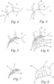
- Figure 3 schematically represents a view of the bone 10 of the upper jaw 2 from figures 1 and 2 . More specifically, this figure schematically represents the three-dimensional image of the part of the upper jaw 2 which is indicated in figures 1 and 2 by a rectangle 9.
- the structure of the bone 10 is visible (not represented in the figure).
- the cortical bone thickness and the density of the bone 10 can be derived from this image.
- a position and orientation are selected for each of the screws as a function of the structure and density of the bone. More specifically, a location with optimal bone quality is selected, meaning a location with a cortical bone thickness that is as high as possible and a bone density that is as high as possible.
- the position and orientation, as well as the diameter and length of the screws to be used are thus selected as a function of the location having the best possible bone quality. In this manner is defined a borehole 11 for every screw 6 having a borehole axis 12 in relation to said bone 10.
- a disc-shaped volume 13 with a circular section is selected which should contain the heads of the screws 6 concerned.
- This volume 13 is placed against the surface 14 of the bone 10 when designing the bone anchor, as represented in figure 4 . It is made sure hereby that the axis of this volume 13 coincides with the borehole axis 12.
- the anchor plate 5 On the basis of this three-dimensional digital image and the selected position and orientation for said screws 6, the anchor plate 5 is then designed.
- the position of said volumes 13 thus defines, for each of the screws 6, a recess with an axis which coincides with the borehole axis 12. These recesses make it possible to fix the anchor plate 5 to the bone 10 by means of the screws 6.
- the anchor plate 5 is designed such that it connects the different volumes 13 to one another. In this design it is ensured that the bone side 15 of the anchor plate 5 connects to the surface 14 of the bone 10, as is schematically represented in figure 5 .
- the drilling template 17 is designed, as is represented in figure 6 .
- a cylindrical recess 18 having a central axis 19 is hereby provided in the drilling template 17.
- the borehole axis 12 for each of the screws 6 hereby coincides with the central axis 19 of the corresponding cylindrical recess 18.
- the diameter of these cylindrical recesses is equal to or larger than the diameter of the head of the corresponding screw 6.
- the cylindrical recesses 18 are thus designed such that, on the one hand, they make it possible to guide a drill or a cutter and, on the other hand, said screws 6 can be screwed in the bone through these recesses 18.
- the drilling template 17 it is made sure that the latter can connect to the free side 16 of the anchor plate 5 in a fitting manner, as is represented in figure 6 , whereby the borehole axis 12 for each of the screws 6 coincides with the central axis 19 of the corresponding cylindrical recess 18.
- the drilling template 17 does not have to connect in a fitting manner to the free surface of the anchor plate 5 over a continuous surface, as is represented in figures 6 to 10 .
- the drilling template 17 it is for example possible for the drilling template 17 to connect to the free surface of the anchor plate 5 only via one or several contact zones. Such contact zones may connect for example to the recesses 18 or the open end of the latter.
- the drilling template 17 and the bone anchor with the anchor plate 5 have thus been designed, whereby the drilling template can be connected to the free side of the anchor plate, they are manufactured. This is preferably done by means of a rapid prototyping technique such as an additive manufacturing method.
- the bone anchor is for example made of titanium produced by means of selective laser melting production (SLM).
- SLM selective laser melting production
- the drilling template 17 can be manufactured in the same way, but it can also be made of plastic.
- Figure 7 schematically represents a side view of an anchor plate 5 of a bone anchor
- figure 8 represents a schematic side view of the accompanying drilling template 17.
- the drilling template 17 may additionally have a surface which can be provided over the teeth of the corresponding jaw in a fitting manner.
- a three-dimensional digital image of the teeth is advantageously added to the already generated three-dimensional digital image of the bone.
- a three-dimensional digital image is generated by laser scanning the teeth or a physical model of the teeth, such as a gypsum model.
- This three-dimensional digital image of the teeth is then merged with the three-dimensional digital image of the bone by applying, for example, a 'best fit' algorithm.
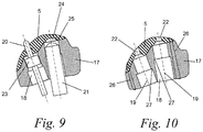
- Figure 9 schematically represents a drill 20 and a cutter 21 while the anchor plate 5 is being manufactured. Once the anchor plate 5 from figure 7 and the drilling template 17 from figure 8 have been obtained, they are placed against one another as represented in figure 9 .
- the drilling template 17 is hereby placed against the free side 16 of the anchor plate 5 of the bone anchor, such that the axis of the recesses to be provided in the anchor plate 5 coincides with said central axis 19 of the corresponding cylindrical recesses 18 in the drilling template 17. This implies that the axis of the volume 13 coincides with the central axis 19 of the cylindrical recesses 18.
- the recesses 22 for the screws 6 are provided in the anchor plate 5 by guiding a drill 20 through the corresponding cylindrical recesses 18.
- the drill 20 has a cylindrical coaxial guide 23 which is guided in the cylindrical recesses 18 in a fitting and coaxial manner.
- the heads of the screws 6 are preferably countersunk in the free side 16 of the anchor plate 5.
- a depression 24 is milled in the surface of the anchor plate 5 by guiding a cutter 21 through the corresponding cylindrical recess 18.
- a depression 24 whose dimensions correspond to those of the head of the corresponding screw 6, as is schematically represented in figure 9 .
- the diameter of the cylindrical recesses 18 must be slightly larger than that of the volumes 13 or than the diameter of the screw heads, such that the surface of the free side 16 of the anchor plate 5 which connects to this volume 13 forms a stop 25 for the cutter 21.
- the recesses 22 and the depressions 24 must not necessarily be provided by drilling or by milling as described above, but they can also be provided by manufacturing the bone anchor with the anchor plate 5 by means of a rapid prototyping technique such as for example an additive manufacturing technique, more specifically SLM.
- the drilling template 17 is placed against the free side 16 of the anchor plate 5 of the bone anchor, as represented in figure 10 . These are placed against one another in such a way that the axis of the recesses 22 of the anchor plate 5 coincides with the central axis 19 of the corresponding cylindrical recesses 18 in the drilling template 17. Next, the bone anchor and the drilling template 17 are connected to each other in a detachable manner.
- the drilling template 17 protrudes for example laterally from the anchor plate 5 of the bone anchor.
- ducts through which a thin loop-shaped wire 26 is inserted which runs over the bone side of the anchor plate.
- this wire 26 connects the anchor plate 5 to the bone anchor 17.
- a wire may for example consist of a steel wire having a diameter of 0.010".
- the drilling template 17 After the drilling template 17 has thus been connected to the bone anchor in a detachable manner, the drilling template 17 is positioned in the oral cavity, whereby the anchor plate 5 rests against the surface 14 of the bone 10. Naturally, the bone 10 must first be exposed by means of a surgical procedure by temporarily displacing tissue.
- the bore holes 11 are provided by guiding a drill through the different cylindrical recesses 18 of the drilling template 17.
- This drill has for example a cylindrical collar which is guided through the cylindrical recesses 18 while drilling until a stop 27 for this collar is reached in the recess 18.
- this stop 27 consists of an annular surface with a central axis which coincides with the central axis 19 of the cylindrical recesses 18.
- a screw is screwed in the borehole through each of the cylindrical recesses 18 of the drilling template 17.
- the heads of the screws 6 in the depression 24 hereby rest in the surface of the anchor plate 5, such that the latter is fixed to the bone.
- the wire 26 is pulled out of the drilling template, such that it can be removed from the anchor plate 5 and such that the drilling template can be removed as well from the anchor plate 5.
- the screws 6 can possibly be tightened somewhat further once the drilling template has been removed, and the anchor plate is coated with the previously displaced tissue.
Landscapes
- Health & Medical Sciences (AREA)
- Life Sciences & Earth Sciences (AREA)
- Animal Behavior & Ethology (AREA)
- Veterinary Medicine (AREA)
- Public Health (AREA)
- General Health & Medical Sciences (AREA)
- Oral & Maxillofacial Surgery (AREA)
- Dentistry (AREA)
- Epidemiology (AREA)
- Orthopedic Medicine & Surgery (AREA)
- Engineering & Computer Science (AREA)
- Surgery (AREA)
- Medical Informatics (AREA)
- Biomedical Technology (AREA)
- Heart & Thoracic Surgery (AREA)
- Molecular Biology (AREA)
- Nuclear Medicine, Radiotherapy & Molecular Imaging (AREA)
- Radiology & Medical Imaging (AREA)
- Physics & Mathematics (AREA)
- Biophysics (AREA)
- High Energy & Nuclear Physics (AREA)
- Optics & Photonics (AREA)
- Pathology (AREA)
- Theoretical Computer Science (AREA)
- Pulmonology (AREA)
- Robotics (AREA)
- Surgical Instruments (AREA)
Claims (15)
- Procédé de fabrication d'au moins un ancrage osseux (1, 3) et d'un gabarit de perçage correspondant (17), dans lequel l'ancrage osseux (1, 3) présente une plaque d'ancrage (5) qui doit être fixée à l'aide d'une ou de plusieurs vis (6) pourvue (s) de têtes de vis contre la surface (14) d'un os (10), de telle sorte que la plaque d'ancrage (5) présente un côté os (15) qui doit être connecté à la surface (14) de l'os (10) et un côté libre (16) opposé audit côté os (15), dans lequel
une image numérique tridimensionnelle de l'os (10) est générée;
sur la base de cette image tridimensionnelle, une position et une orientation pour chacune desdites une ou plusieurs vis (6) sont sélectionnées en fonction de la structure et de la densité de l'os (10), dans lequel un trou de forage (11) présentant un axe de trou de forage (12) est ainsi défini pour ladite vis (6) par rapport audit os;
en partant de ladite image numérique tridimensionnelle et desdites position et orientation sélectionnées pour lesdites une ou plusieurs vis (6), ladite plaque d'ancrage (5) est conçue, pour chacune desdites vis (6), avec un évidement (22) présentant un axe qui coïncide avec ledit axe de trou de forage (12) dans le but de permettre que la plaque d'ancrage (5) soit fixée audit os (10) à travers cet évidement (22) à l'aide desdites vis (6), de telle sorte que son côté os (15) se connecte à la surface (14) de l'os (10), dans lequel lesdites vis (6) s'étendent dans l'os suivant la position et l'orientation sélectionnées,
caractérisé en ce que ledit gabarit de perçage (17) est conçu, pour chacune desdites vis (16), avec un évidement cylindrique (18) présentant un axe central (19) pour guider un foret ou une fraise, dans lequel la forme du gabarit de perçage (17) est conçue de manière à être placée contre ledit côté libre (16) de la plaque d'ancrage (5) de telle sorte que la forme du gabarit de perçage (17) s'agence contre ledit côté libre (16) de la plaque d'ancrage (5), dans lequel ledit axe de trou de forage (12) pour chacune des vis (6) coïncide avec ledit axe central (19) de l'évidement cylindrique correspondant (18), et le diamètre dudit évidement cylindrique (18) est égal ou supérieur au diamètre de la tête de la vis correspondante (6), dans lequel, une fois que le gabarit de perçage (17) et l'ancrage osseux (1, 3) ont été conçus, ils sont fabriqués. - Procédé selon la revendication 1, dans lequel ledit gabarit de perçage (17) est placé contre le côté libre (16) de la plaque d'ancrage (5) de l'ancrage osseux (1, 3) et, ensuite, l'ancrage osseux (1, 3) et le gabarit de perçage (17) sont connectés l'un à l'autre d'une manière détachable, de telle sorte que l'axe des évidements (22) de la plaque d'ancrage (5) coïncide avec ledit axe central (19) des évidements cylindriques correspondants (18) dans le gabarit de perçage (17).
- Procédé selon la revendication 1 ou 2, dans lequel lesdits évidements cylindriques (18) dans le gabarit de perçage (17) sont pourvus d'un arrêt (25, 27) pour un foret de manière à permettre de pratiquer des trous de forage dans ledit os (10) qui présentent une profondeur prédéterminée.
- Procédé selon l'une quelconque des revendications 1 à 3, dans lequel ledit os (10) comprend au moins une partie d'une mâchoire supérieure ou inférieure (2, 4) contre laquelle ladite plaque d'ancrage (5) doit être fixée et dans lequel, à ladite image numérique tridimensionnelle de l'os (10), une image numérique tridimensionnelle d'au moins une dent qui est présente dans ladite mâchoire (2, 4) est ajoutée, dans lequel lors de la conception dudit gabarit de perçage (17), une surface est prévue au niveau de ce gabarit de perçage (17) qui peut se connecter de façon univoque à ladite au moins une dent.
- Procédé selon la revendication 4, dans lequel une tomodensitométrie à faisceau conique de ladite mâchoire (2, 4) est effectuée dans le but de générer ladite image numérique tridimensionnelle de l'os (10).
- Procédé selon la revendication 4 ou 5, dans lequel ladite image numérique tridimensionnelle de ladite au moins une dent est obtenue par balayage optique de celle-ci ou par balayage d'un modèle physique de la mâchoire avec ladite au moins une dent, dans lequel cette image tridimensionnelle de ladite au moins une dent est ajoutée à ladite image de l'os en incorporant celle-ci dans cette image.
- Procédé selon l'une quelconque des revendications 4 à 6, dans lequel un élément de connexion allongé (7) présentant un élément de montage (8) pour monter des moyens orthodontiques ou orthopédiques sur ladite plaque d'ancrage est prévu, dans lequel cet élément de connexion (7) connecte l'élément de montage (8) à la plaque d'ancrage (5) et peut s'étendre à travers la gencive ou la muqueuse dans la cavité buccale.
- Procédé selon l'une quelconque des revendications 1 à 7, dans lequel ledit gabarit de perçage est placé contre le côté libre (16) de la plaque d'ancrage (5) de l'ancrage osseux (1, 3), de telle sorte que le axe des évidements (22) de la plaque d'ancrage (5) coïncide avec ledit axe central (19) de l'évidement cylindrique correspondant (18) dans le gabarit de perçage (17), dans lequel lesdits évidements sont ensuite forés dans la plaque d'ancrage (5) à l'aide d'un foret pendant que ce dernier est guidé dans l'évidement cylindrique correspondant (18) du gabarit de perçage (17).
- Procédé selon l'une quelconque des revendications 1 à 8, dans lequel ledit gabarit de perçage est placé contre le côté libre de la plaque d'ancrage de l'ancrage osseux, de telle sorte que l'axe des évidements de la plaque d'ancrage coïncide avec ledit axe central des évidements cylindriques correspondants dans le gabarit de perçage, dans lequel ensuite, pour la tête de chacune desdites une ou plusieurs vis, une dépression est fraisée dans la surface de la plaque d'ancrage en guidant une fraise à travers l'évidement cylindrique correspondant, dans lequel on obtient une dépression dont les dimensions correspondent à celles de la tête de la vis correspondante.
- Ensemble comprenant un gabarit de perçage (17) et au moins un ancrage osseux (1, 3) et une ou plusieurs vis (6) pour fixer l'ancrage osseux à un os (10), dans lequel l'ancrage osseux présente une plaque d'ancrage (5) comportant des évidements (22) pour lesdites vis (6) pourvues de têtes de vis dans le but de fixer la plaque d'ancrage (5) à la surface (14) de l'os, dans lequel la plaque d'ancrage (5) présente un côté os (15) qui doit être connecté à la surface (14) de l'os (10) et un côté libre (16) opposé audit côté os (15), dans lequel ledit gabarit de perçage (17) comporte un évidement cylindrique (18) pour chacune desdites vis (6) avec un axe central (19) pour guider un foret ou une fraise, caractérisé en ce que la forme du gabarit de perçage (17) s'agence contre ledit côté libre (16) de la plaque d'ancrage (5), de telle sorte que ledit axe central (19) de chacun des évidements cylindriques (18) coïncide avec l'axe d'un évidement correspondant (22) dans ladite plaque d'ancrage (5), dans lequel le diamètre desdits évidements cylindriques (18) est égal ou supérieur au diamètre de la tête de la vis correspondante (6).
- Ensemble selon la revendication 10, dans lequel un élément de connexion allongé pourvu d'un élément de montage pour monter des outils orthodontiques ou orthopédiques sur ladite plaque d'ancrage est prévu.
- Ensemble selon la revendication 10 ou 11, dans lequel ledit gabarit de perçage présente des moyens de fixation pour fixer celui-ci d'une façon détachable sur le côté libre de ladite plaque d'ancrage.
- Ensemble selon l'une quelconque des revendications 10 à 12, dans lequel lesdits évidements cylindriques dans le gabarit de perçage présentent un arrêt pour un foret de manière à permettre de pratique des trous de forage dans ledit os qui présentent une profondeur prédéterminée.
- Ensemble selon l'une quelconque des revendications 10 à 13, dans lequel ledit gabarit de perçage présente une surface qui peut se connecter de façon univoque à une partie de la surface d'au moins une dent d'une mâchoire, de telle sorte que le gabarit de perçage puisse être placé dans la cavité buccale d'une manière univoque prédéterminée.
- Ensemble selon l'une quelconque des revendications 10 à 14, dans lequel lesdits évidements de la plaque d'ancrage se connectent à une dépression dans sa surface libre, de telle sorte que, lorsque la plaque d'ancrage est fixée à l'os à l'aide desdites vis, les têtes de ces vis seront fraisées dans la surface libre de la plaque d'ancrage.
Applications Claiming Priority (2)
| Application Number | Priority Date | Filing Date | Title |
|---|---|---|---|
| BE2015/0136A BE1023125B1 (nl) | 2015-05-08 | 2015-05-08 | Botanker met een op dit botanker aansluitende boormal en werkwijze voor het vervaardigen van het botanker en de boormal |
| PCT/IB2016/052637 WO2016181286A1 (fr) | 2015-05-08 | 2016-05-09 | Ancrage osseux avec raccordement de gabarit de perçage à cet ancrage osseux et procédé de fabrication de l'ancrage osseux et du gabarit de perçage |
Publications (3)
| Publication Number | Publication Date |
|---|---|
| EP3294189A1 EP3294189A1 (fr) | 2018-03-21 |
| EP3294189B1 true EP3294189B1 (fr) | 2019-07-10 |
| EP3294189B8 EP3294189B8 (fr) | 2019-08-21 |
Family
ID=54007435
Family Applications (1)
| Application Number | Title | Priority Date | Filing Date |
|---|---|---|---|
| EP16730897.2A Active EP3294189B8 (fr) | 2015-05-08 | 2016-05-09 | Ancrage osseux avec raccordement de gabarit de perçage à cet ancrage osseux et procédé de fabrication de l'ancrage osseux et du gabarit de perçage |
Country Status (6)
| Country | Link |
|---|---|
| US (2) | US11376025B2 (fr) |
| EP (1) | EP3294189B8 (fr) |
| BE (1) | BE1023125B1 (fr) |
| BR (1) | BR112017023923B1 (fr) |
| CA (1) | CA2985026C (fr) |
| WO (1) | WO2016181286A1 (fr) |
Families Citing this family (5)
| Publication number | Priority date | Publication date | Assignee | Title |
|---|---|---|---|---|
| BE1026320B1 (nl) * | 2018-05-30 | 2020-01-13 | Tita Link B V B A | Kaakverplaatsingssysteem en werkwijze voor het vervaardigen van een dergelijk systeem voor de behandeling van slaapapneu en/of snurken. |
| US10702319B2 (en) * | 2018-07-09 | 2020-07-07 | Robert G. Hale | Apparatus and method for a transalveolar dental implant |
| BE1026696A9 (nl) * | 2018-10-08 | 2020-05-14 | Tita Link B V B A | Botanker voor een boven- of onderkaak met een bijhorende boormal |
| CN111821044B (zh) * | 2020-04-07 | 2021-02-05 | 南京医科大学附属口腔医院 | 适用于后牙*龈修复空间不足3mm的插销式桩核一体冠 |
| CN111714233B (zh) * | 2020-07-07 | 2023-01-31 | 徐茂 | 一种正畸种植支抗体及其代型和使用它们的牙齿矫正方法 |
Family Cites Families (15)
| Publication number | Priority date | Publication date | Assignee | Title |
|---|---|---|---|---|
| US5320529A (en) * | 1992-09-09 | 1994-06-14 | Howard C. Weitzman | Method and apparatus for locating an ideal site for a dental implant and for the precise surgical placement of that implant |
| US5439381A (en) * | 1992-09-28 | 1995-08-08 | Cohen; Howard | Dental implant apparatus and method |
| IL138457A0 (en) * | 2000-09-09 | 2001-10-31 | Advanced Dental Engineering Lt | Bi-cortical dental implant |
| US6827574B2 (en) * | 2001-04-12 | 2004-12-07 | Kevin L. Payton | Skeletal transmucosal orthodontic plate and method |
| BE1013760A6 (nl) * | 2001-05-17 | 2002-07-02 | Clerck Hugo De | Orthodontisch implantaat. |
| US8251698B2 (en) * | 2001-05-17 | 2012-08-28 | Hugo De Clerck | Orthodontic implant |
| US20050033430A1 (en) * | 2003-08-05 | 2005-02-10 | Russell Powers | Surgical kit and method for providing sterilized equipment for use in spinal surgery |
| FR2942125B1 (fr) * | 2009-02-17 | 2012-02-17 | Obl | Ensemble sur mesure d'au moins deux plaques d'osteosynthese, elles-memes preparees sur mesure, et procede de mise en place desdites plaques |
| FR2948278B1 (fr) * | 2009-07-22 | 2011-09-16 | Philippe Dacremont | Dispositif de stabilisation additionnel pour implant dentaire endo-osseux |
| US9504533B2 (en) * | 2011-09-16 | 2016-11-29 | Ibur, Llc | Edentulous surgical guide |
| US20140248583A1 (en) * | 2013-03-04 | 2014-09-04 | EdMiDent, LLC | Support mechanism |
| EP3027132A4 (fr) | 2013-08-02 | 2017-03-15 | Flower Orthopedic Corporation | Kits d'implants orthopédiques stériles à usage unique et procédés de mise à disposition de ces kits |
| BE1026320B1 (nl) * | 2018-05-30 | 2020-01-13 | Tita Link B V B A | Kaakverplaatsingssysteem en werkwijze voor het vervaardigen van een dergelijk systeem voor de behandeling van slaapapneu en/of snurken. |
| BE1026696A9 (nl) * | 2018-10-08 | 2020-05-14 | Tita Link B V B A | Botanker voor een boven- of onderkaak met een bijhorende boormal |
| EP4241723B1 (fr) * | 2020-06-16 | 2025-07-16 | Biomet 3I, LLC | Système comprenant un guide chirurgical, un foret et un corps de guide amovible |
-
2015
- 2015-05-08 BE BE2015/0136A patent/BE1023125B1/nl not_active IP Right Cessation
-
2016
- 2016-05-09 US US15/571,883 patent/US11376025B2/en active Active
- 2016-05-09 BR BR112017023923-0A patent/BR112017023923B1/pt active IP Right Grant
- 2016-05-09 EP EP16730897.2A patent/EP3294189B8/fr active Active
- 2016-05-09 WO PCT/IB2016/052637 patent/WO2016181286A1/fr not_active Ceased
- 2016-05-09 CA CA2985026A patent/CA2985026C/fr active Active
-
2022
- 2022-07-04 US US17/810,637 patent/US20220401116A1/en active Pending
Non-Patent Citations (1)
| Title |
|---|
| None * |
Also Published As
| Publication number | Publication date |
|---|---|
| BR112017023923A2 (pt) | 2018-07-17 |
| US20220401116A1 (en) | 2022-12-22 |
| BR112017023923B1 (pt) | 2021-02-17 |
| US20180132870A1 (en) | 2018-05-17 |
| EP3294189B8 (fr) | 2019-08-21 |
| CA2985026C (fr) | 2023-09-26 |
| EP3294189A1 (fr) | 2018-03-21 |
| CA2985026A1 (fr) | 2016-11-17 |
| US11376025B2 (en) | 2022-07-05 |
| BE1023125B1 (nl) | 2016-11-25 |
| WO2016181286A1 (fr) | 2016-11-17 |
Similar Documents
| Publication | Publication Date | Title |
|---|---|---|
| US20220401116A1 (en) | Bone anchor with a drilling template connecting to this bone anchor and method for manufacturing the bone anchor and the drilling template | |
| KR101479186B1 (ko) | 뼈 조직에 치과 임플란트를 고정하는 디바이스, 수술용 템플릿 제조방법 및 뼈 조직에 치과 임플란트를 고정하는 방법 | |
| JP6063516B2 (ja) | 正確な骨及び軟質組織デジタル歯科用モデルを生成する方法 | |
| US8439675B2 (en) | Method for producing a bone prosthesis or a pre-implant simulation, and equipment used | |
| US7824181B2 (en) | Custom-fit implant surgery guide and associated milling cutter, method for their production, and their use | |
| US9011148B2 (en) | Surgical guide system for dental implantology and method for making the same | |
| CN103501723B (zh) | 骨移植体和用于移植骨移植体的牙移植体钻孔设备 | |
| TW201634012A (zh) | 製作牙科手術導板及局部缺牙患者植入贗復體之方法 | |
| JP7050662B2 (ja) | カスタマイズされた歯科インプラントおよび関連する冶具 | |
| KR101566456B1 (ko) | 임플란트용 드릴 및 이를 구비하는 임플란트용 드릴 장치 | |
| US9050665B2 (en) | Modular template for drilling holes and method of making same | |
| EP3750506B1 (fr) | Prothèse dentaire et sa methode de fabrication | |
| JP5616738B2 (ja) | サージカルガイド及び埋入孔穿孔具 | |
| CN113786254B (zh) | 一种穿颧种植手术导板的制作方法 | |
| US20140329196A1 (en) | System And Method For A Bone Engaging Dental Implant Surgical Stent Placement System | |
| JP2011501998A (ja) | 精密誘導植立のためのインプラント用のステント固定体 | |
| EP3597140A1 (fr) | Modèle modulaire pour forer des trous et son procédé de fabrication | |
| USRE47368E1 (en) | Modular template for drilling holes and method of making same | |
| KR101455067B1 (ko) | 임플란트 시술유도 홀 공정용 부재 |
Legal Events
| Date | Code | Title | Description |
|---|---|---|---|
| STAA | Information on the status of an ep patent application or granted ep patent |
Free format text: STATUS: THE INTERNATIONAL PUBLICATION HAS BEEN MADE |
|
| PUAI | Public reference made under article 153(3) epc to a published international application that has entered the european phase |
Free format text: ORIGINAL CODE: 0009012 |
|
| STAA | Information on the status of an ep patent application or granted ep patent |
Free format text: STATUS: REQUEST FOR EXAMINATION WAS MADE |
|
| 17P | Request for examination filed |
Effective date: 20171201 |
|
| AK | Designated contracting states |
Kind code of ref document: A1 Designated state(s): AL AT BE BG CH CY CZ DE DK EE ES FI FR GB GR HR HU IE IS IT LI LT LU LV MC MK MT NL NO PL PT RO RS SE SI SK SM TR |
|
| AX | Request for extension of the european patent |
Extension state: BA ME |
|
| DAV | Request for validation of the european patent (deleted) | ||
| DAX | Request for extension of the european patent (deleted) | ||
| GRAP | Despatch of communication of intention to grant a patent |
Free format text: ORIGINAL CODE: EPIDOSNIGR1 |
|
| STAA | Information on the status of an ep patent application or granted ep patent |
Free format text: STATUS: GRANT OF PATENT IS INTENDED |
|
| INTG | Intention to grant announced |
Effective date: 20181217 |
|
| GRAS | Grant fee paid |
Free format text: ORIGINAL CODE: EPIDOSNIGR3 |
|
| GRAA | (expected) grant |
Free format text: ORIGINAL CODE: 0009210 |
|
| STAA | Information on the status of an ep patent application or granted ep patent |
Free format text: STATUS: THE PATENT HAS BEEN GRANTED |
|
| AK | Designated contracting states |
Kind code of ref document: B1 Designated state(s): AL AT BE BG CH CY CZ DE DK EE ES FI FR GB GR HR HU IE IS IT LI LT LU LV MC MK MT NL NO PL PT RO RS SE SI SK SM TR |
|
| REG | Reference to a national code |
Ref country code: GB Ref legal event code: FG4D |
|
| REG | Reference to a national code |
Ref country code: CH Ref legal event code: EP Ref country code: AT Ref legal event code: REF Ref document number: 1152731 Country of ref document: AT Kind code of ref document: T Effective date: 20190715 |
|
| RAP2 | Party data changed (patent owner data changed or rights of a patent transferred) |
Owner name: TITA-LINK B.V.B.A. |
|
| REG | Reference to a national code |
Ref country code: CH Ref legal event code: PK Free format text: BERICHTIGUNG B8 |
|
| REG | Reference to a national code |
Ref country code: DE Ref legal event code: R096 Ref document number: 602016016705 Country of ref document: DE |
|
| REG | Reference to a national code |
Ref country code: IE Ref legal event code: FG4D |
|
| REG | Reference to a national code |
Ref country code: LT Ref legal event code: MG4D |
|
| REG | Reference to a national code |
Ref country code: NL Ref legal event code: FP |
|
| REG | Reference to a national code |
Ref country code: AT Ref legal event code: MK05 Ref document number: 1152731 Country of ref document: AT Kind code of ref document: T Effective date: 20190710 |
|
| PG25 | Lapsed in a contracting state [announced via postgrant information from national office to epo] |
Ref country code: FI Free format text: LAPSE BECAUSE OF FAILURE TO SUBMIT A TRANSLATION OF THE DESCRIPTION OR TO PAY THE FEE WITHIN THE PRESCRIBED TIME-LIMIT Effective date: 20190710 Ref country code: HR Free format text: LAPSE BECAUSE OF FAILURE TO SUBMIT A TRANSLATION OF THE DESCRIPTION OR TO PAY THE FEE WITHIN THE PRESCRIBED TIME-LIMIT Effective date: 20190710 Ref country code: BG Free format text: LAPSE BECAUSE OF FAILURE TO SUBMIT A TRANSLATION OF THE DESCRIPTION OR TO PAY THE FEE WITHIN THE PRESCRIBED TIME-LIMIT Effective date: 20191010 Ref country code: SE Free format text: LAPSE BECAUSE OF FAILURE TO SUBMIT A TRANSLATION OF THE DESCRIPTION OR TO PAY THE FEE WITHIN THE PRESCRIBED TIME-LIMIT Effective date: 20190710 Ref country code: NO Free format text: LAPSE BECAUSE OF FAILURE TO SUBMIT A TRANSLATION OF THE DESCRIPTION OR TO PAY THE FEE WITHIN THE PRESCRIBED TIME-LIMIT Effective date: 20191010 Ref country code: AT Free format text: LAPSE BECAUSE OF FAILURE TO SUBMIT A TRANSLATION OF THE DESCRIPTION OR TO PAY THE FEE WITHIN THE PRESCRIBED TIME-LIMIT Effective date: 20190710 Ref country code: LT Free format text: LAPSE BECAUSE OF FAILURE TO SUBMIT A TRANSLATION OF THE DESCRIPTION OR TO PAY THE FEE WITHIN THE PRESCRIBED TIME-LIMIT Effective date: 20190710 Ref country code: PT Free format text: LAPSE BECAUSE OF FAILURE TO SUBMIT A TRANSLATION OF THE DESCRIPTION OR TO PAY THE FEE WITHIN THE PRESCRIBED TIME-LIMIT Effective date: 20191111 |
|
| PG25 | Lapsed in a contracting state [announced via postgrant information from national office to epo] |
Ref country code: GR Free format text: LAPSE BECAUSE OF FAILURE TO SUBMIT A TRANSLATION OF THE DESCRIPTION OR TO PAY THE FEE WITHIN THE PRESCRIBED TIME-LIMIT Effective date: 20191011 Ref country code: LV Free format text: LAPSE BECAUSE OF FAILURE TO SUBMIT A TRANSLATION OF THE DESCRIPTION OR TO PAY THE FEE WITHIN THE PRESCRIBED TIME-LIMIT Effective date: 20190710 Ref country code: ES Free format text: LAPSE BECAUSE OF FAILURE TO SUBMIT A TRANSLATION OF THE DESCRIPTION OR TO PAY THE FEE WITHIN THE PRESCRIBED TIME-LIMIT Effective date: 20190710 Ref country code: AL Free format text: LAPSE BECAUSE OF FAILURE TO SUBMIT A TRANSLATION OF THE DESCRIPTION OR TO PAY THE FEE WITHIN THE PRESCRIBED TIME-LIMIT Effective date: 20190710 Ref country code: RS Free format text: LAPSE BECAUSE OF FAILURE TO SUBMIT A TRANSLATION OF THE DESCRIPTION OR TO PAY THE FEE WITHIN THE PRESCRIBED TIME-LIMIT Effective date: 20190710 Ref country code: IS Free format text: LAPSE BECAUSE OF FAILURE TO SUBMIT A TRANSLATION OF THE DESCRIPTION OR TO PAY THE FEE WITHIN THE PRESCRIBED TIME-LIMIT Effective date: 20191110 |
|
| PG25 | Lapsed in a contracting state [announced via postgrant information from national office to epo] |
Ref country code: TR Free format text: LAPSE BECAUSE OF FAILURE TO SUBMIT A TRANSLATION OF THE DESCRIPTION OR TO PAY THE FEE WITHIN THE PRESCRIBED TIME-LIMIT Effective date: 20190710 |
|
| PG25 | Lapsed in a contracting state [announced via postgrant information from national office to epo] |
Ref country code: EE Free format text: LAPSE BECAUSE OF FAILURE TO SUBMIT A TRANSLATION OF THE DESCRIPTION OR TO PAY THE FEE WITHIN THE PRESCRIBED TIME-LIMIT Effective date: 20190710 Ref country code: PL Free format text: LAPSE BECAUSE OF FAILURE TO SUBMIT A TRANSLATION OF THE DESCRIPTION OR TO PAY THE FEE WITHIN THE PRESCRIBED TIME-LIMIT Effective date: 20190710 Ref country code: RO Free format text: LAPSE BECAUSE OF FAILURE TO SUBMIT A TRANSLATION OF THE DESCRIPTION OR TO PAY THE FEE WITHIN THE PRESCRIBED TIME-LIMIT Effective date: 20190710 Ref country code: DK Free format text: LAPSE BECAUSE OF FAILURE TO SUBMIT A TRANSLATION OF THE DESCRIPTION OR TO PAY THE FEE WITHIN THE PRESCRIBED TIME-LIMIT Effective date: 20190710 Ref country code: IT Free format text: LAPSE BECAUSE OF FAILURE TO SUBMIT A TRANSLATION OF THE DESCRIPTION OR TO PAY THE FEE WITHIN THE PRESCRIBED TIME-LIMIT Effective date: 20190710 |
|
| PG25 | Lapsed in a contracting state [announced via postgrant information from national office to epo] |
Ref country code: CZ Free format text: LAPSE BECAUSE OF FAILURE TO SUBMIT A TRANSLATION OF THE DESCRIPTION OR TO PAY THE FEE WITHIN THE PRESCRIBED TIME-LIMIT Effective date: 20190710 Ref country code: SK Free format text: LAPSE BECAUSE OF FAILURE TO SUBMIT A TRANSLATION OF THE DESCRIPTION OR TO PAY THE FEE WITHIN THE PRESCRIBED TIME-LIMIT Effective date: 20190710 Ref country code: SM Free format text: LAPSE BECAUSE OF FAILURE TO SUBMIT A TRANSLATION OF THE DESCRIPTION OR TO PAY THE FEE WITHIN THE PRESCRIBED TIME-LIMIT Effective date: 20190710 Ref country code: IS Free format text: LAPSE BECAUSE OF FAILURE TO SUBMIT A TRANSLATION OF THE DESCRIPTION OR TO PAY THE FEE WITHIN THE PRESCRIBED TIME-LIMIT Effective date: 20200224 |
|
| REG | Reference to a national code |
Ref country code: DE Ref legal event code: R097 Ref document number: 602016016705 Country of ref document: DE |
|
| PLBE | No opposition filed within time limit |
Free format text: ORIGINAL CODE: 0009261 |
|
| STAA | Information on the status of an ep patent application or granted ep patent |
Free format text: STATUS: NO OPPOSITION FILED WITHIN TIME LIMIT |
|
| PG2D | Information on lapse in contracting state deleted |
Ref country code: IS |
|
| 26N | No opposition filed |
Effective date: 20200603 |
|
| PG25 | Lapsed in a contracting state [announced via postgrant information from national office to epo] |
Ref country code: SI Free format text: LAPSE BECAUSE OF FAILURE TO SUBMIT A TRANSLATION OF THE DESCRIPTION OR TO PAY THE FEE WITHIN THE PRESCRIBED TIME-LIMIT Effective date: 20190710 |
|
| PG25 | Lapsed in a contracting state [announced via postgrant information from national office to epo] |
Ref country code: CH Free format text: LAPSE BECAUSE OF NON-PAYMENT OF DUE FEES Effective date: 20200531 Ref country code: MC Free format text: LAPSE BECAUSE OF FAILURE TO SUBMIT A TRANSLATION OF THE DESCRIPTION OR TO PAY THE FEE WITHIN THE PRESCRIBED TIME-LIMIT Effective date: 20190710 Ref country code: LI Free format text: LAPSE BECAUSE OF NON-PAYMENT OF DUE FEES Effective date: 20200531 |
|
| GBPC | Gb: european patent ceased through non-payment of renewal fee |
Effective date: 20200509 |
|
| PG25 | Lapsed in a contracting state [announced via postgrant information from national office to epo] |
Ref country code: LU Free format text: LAPSE BECAUSE OF NON-PAYMENT OF DUE FEES Effective date: 20200509 |
|
| PG25 | Lapsed in a contracting state [announced via postgrant information from national office to epo] |
Ref country code: GB Free format text: LAPSE BECAUSE OF NON-PAYMENT OF DUE FEES Effective date: 20200509 Ref country code: IE Free format text: LAPSE BECAUSE OF NON-PAYMENT OF DUE FEES Effective date: 20200509 |
|
| PG25 | Lapsed in a contracting state [announced via postgrant information from national office to epo] |
Ref country code: MT Free format text: LAPSE BECAUSE OF FAILURE TO SUBMIT A TRANSLATION OF THE DESCRIPTION OR TO PAY THE FEE WITHIN THE PRESCRIBED TIME-LIMIT Effective date: 20190710 Ref country code: CY Free format text: LAPSE BECAUSE OF FAILURE TO SUBMIT A TRANSLATION OF THE DESCRIPTION OR TO PAY THE FEE WITHIN THE PRESCRIBED TIME-LIMIT Effective date: 20190710 |
|
| PG25 | Lapsed in a contracting state [announced via postgrant information from national office to epo] |
Ref country code: MK Free format text: LAPSE BECAUSE OF FAILURE TO SUBMIT A TRANSLATION OF THE DESCRIPTION OR TO PAY THE FEE WITHIN THE PRESCRIBED TIME-LIMIT Effective date: 20190710 |
|
| PGFP | Annual fee paid to national office [announced via postgrant information from national office to epo] |
Ref country code: NL Payment date: 20250526 Year of fee payment: 10 |
|
| PGFP | Annual fee paid to national office [announced via postgrant information from national office to epo] |
Ref country code: DE Payment date: 20250529 Year of fee payment: 10 |
|
| PGFP | Annual fee paid to national office [announced via postgrant information from national office to epo] |
Ref country code: BE Payment date: 20250531 Year of fee payment: 10 |
|
| PGFP | Annual fee paid to national office [announced via postgrant information from national office to epo] |
Ref country code: FR Payment date: 20250526 Year of fee payment: 10 |