EP3294387B1 - Élément rapporté pour un dispositif ou destiné à être placé sur ledit dispositif pour l'injection d'un liquide dans ou sous la peau - Google Patents
Élément rapporté pour un dispositif ou destiné à être placé sur ledit dispositif pour l'injection d'un liquide dans ou sous la peau Download PDFInfo
- Publication number
- EP3294387B1 EP3294387B1 EP16722653.9A EP16722653A EP3294387B1 EP 3294387 B1 EP3294387 B1 EP 3294387B1 EP 16722653 A EP16722653 A EP 16722653A EP 3294387 B1 EP3294387 B1 EP 3294387B1
- Authority
- EP
- European Patent Office
- Prior art keywords
- attachment
- distal part
- cannula
- distal
- proximal part
- Prior art date
- Legal status (The legal status is an assumption and is not a legal conclusion. Google has not performed a legal analysis and makes no representation as to the accuracy of the status listed.)
- Active
Links
Images







Classifications
-
- A—HUMAN NECESSITIES
- A61—MEDICAL OR VETERINARY SCIENCE; HYGIENE
- A61M—DEVICES FOR INTRODUCING MEDIA INTO, OR ONTO, THE BODY; DEVICES FOR TRANSDUCING BODY MEDIA OR FOR TAKING MEDIA FROM THE BODY; DEVICES FOR PRODUCING OR ENDING SLEEP OR STUPOR
- A61M5/00—Devices for bringing media into the body in a subcutaneous, intra-vascular or intramuscular way; Accessories therefor, e.g. filling or cleaning devices, arm-rests
- A61M5/46—Devices for bringing media into the body in a subcutaneous, intra-vascular or intramuscular way; Accessories therefor, e.g. filling or cleaning devices, arm-rests having means for controlling depth of insertion
-
- A—HUMAN NECESSITIES
- A61—MEDICAL OR VETERINARY SCIENCE; HYGIENE
- A61K—PREPARATIONS FOR MEDICAL, DENTAL OR TOILETRY PURPOSES
- A61K38/00—Medicinal preparations containing peptides
- A61K38/16—Peptides having more than 20 amino acids; Gastrins; Somatostatins; Melanotropins; Derivatives thereof
- A61K38/43—Enzymes; Proenzymes; Derivatives thereof
- A61K38/46—Hydrolases (3)
- A61K38/48—Hydrolases (3) acting on peptide bonds (3.4)
- A61K38/4886—Metalloendopeptidases (3.4.24), e.g. collagenase
- A61K38/4893—Botulinum neurotoxin (3.4.24.69)
-
- A—HUMAN NECESSITIES
- A61—MEDICAL OR VETERINARY SCIENCE; HYGIENE
- A61K—PREPARATIONS FOR MEDICAL, DENTAL OR TOILETRY PURPOSES
- A61K9/00—Medicinal preparations characterised by special physical form
- A61K9/0012—Galenical forms characterised by the site of application
- A61K9/0019—Injectable compositions; Intramuscular, intravenous, arterial, subcutaneous administration; Compositions to be administered through the skin in an invasive manner
-
- A—HUMAN NECESSITIES
- A61—MEDICAL OR VETERINARY SCIENCE; HYGIENE
- A61M—DEVICES FOR INTRODUCING MEDIA INTO, OR ONTO, THE BODY; DEVICES FOR TRANSDUCING BODY MEDIA OR FOR TAKING MEDIA FROM THE BODY; DEVICES FOR PRODUCING OR ENDING SLEEP OR STUPOR
- A61M5/00—Devices for bringing media into the body in a subcutaneous, intra-vascular or intramuscular way; Accessories therefor, e.g. filling or cleaning devices, arm-rests
- A61M5/178—Syringes
- A61M5/31—Details
- A61M5/32—Needles; Details of needles pertaining to their connection with syringe or hub; Accessories for bringing the needle into, or holding the needle on, the body; Devices for protection of needles
- A61M5/34—Constructions for connecting the needle, e.g. to syringe nozzle or needle hub
- A61M5/344—Constructions for connecting the needle, e.g. to syringe nozzle or needle hub using additional parts, e.g. clamping rings or collets
- A61M5/345—Adaptors positioned between needle hub and syringe nozzle
-
- A—HUMAN NECESSITIES
- A61—MEDICAL OR VETERINARY SCIENCE; HYGIENE
- A61M—DEVICES FOR INTRODUCING MEDIA INTO, OR ONTO, THE BODY; DEVICES FOR TRANSDUCING BODY MEDIA OR FOR TAKING MEDIA FROM THE BODY; DEVICES FOR PRODUCING OR ENDING SLEEP OR STUPOR
- A61M2205/00—General characteristics of the apparatus
- A61M2205/58—Means for facilitating use, e.g. by people with impaired vision
- A61M2205/583—Means for facilitating use, e.g. by people with impaired vision by visual feedback
- A61M2205/584—Means for facilitating use, e.g. by people with impaired vision by visual feedback having a color code
Definitions
- the invention relates to an attachment for or on a device for injecting a liquid into or under the skin, for example botulinum toxin in a human patient.
- botox botulinum toxin
- the administration of botox can be difficult because the treating physician has to skillfully set the depth of injection of the syringe by hand at an injection angle of between 45 ° and 90 °.
- a puncture is made subcutaneously with a puncture angle of less than 25 °, it is from the DE 10 2010 001 506 A1 known to lock a cannula for the injection of the liquid to be administered in two positions, the cannula being extended further in the first position and the second position being reached by retracting the cannula.
- a distal part is provided with an internal thread and a proximal part of the attachment is provided with an external thread at its distal end.
- the distal part is screwed onto the external thread of the proximal part.
- a scale is provided in front of the external thread on the proximal part, which, depending on the extent of its covering, shows different maximum numerical values.
- a disadvantage of this arrangement is the low hold of the distal part, if the cannula should protrude little and a maximum number of the scale can be read.
- Another disadvantage is that no discrete positions can be set, and the setting can only be checked optically and not tactilely and acoustically.
- Another disadvantage is that the numerical values on the scale do not indicate the depth of injection, but the shortening of the inserted cannula.
- a further disadvantage is the potential for errors that result from the possibility of selecting different cannulas for use with the device.
- the WO 2013/121307 A1 shows several stable locking positions of the distal part.
- the WO 2012/029082 A1 also shows a two-part attachment for a syringe, wherein a needle of the syringe penetrates both attachment parts when the syringe is supported on the proximal, inner attachment part. The penetration depth can be adjusted by rotating the proximal attachment part in relation to the distal attachment part. This also has the disadvantage of poor stability of the arrangement.
- a syringe for insulin drives on a sled opposite a housing.
- the process is carried out by means of a gear unit which comprises a large ring gear outside the slide and a small ring gear on a rotatable cylinder as part of the slide.
- a screw nut is provided on a syringe attachment, which is also provided as a seat for an apron on the needle-side end of the syringe.
- the DE 200 135 79 U1 further discloses a refillable dosing and injection device in which an insertion depth of a cannula can be determined by means of an adjusting nut.
- an insertion depth of a cannula can be determined by means of an adjusting nut.
- it is from the WO 98/50094 A1 known to hold the needle on an inner body which is provided with an external thread which is rotatable in an internal thread of an outer body. The rotation is done by actuating an adjusting ring.
- the needle is withdrawn from one end and at the same time moved out of the liquid reservoir for the liquid to be injected. If necessary, the liquid reservoir can be replenished by manual actuation become.
- the disadvantage of this is that the entire device is very complex and prone to errors.
- EP 2 388 033 A1 discloses a tube attachment which can be coupled to a syringe and which comprises a decoupling body and a control tube.
- the head tube is coupled to the upper end of the syringe and is slidably movable on the coupling body.
- the head tube also has a hole through which the tip cannula can pass.
- the invention has for its object to provide reliable technical help in the delivery of botox in and under the skin of a human patient.
- an attachment for or on a device for injecting a liquid into or under the skin for example botulinum toxin in a human patient
- the attachment having a proximal part which connects to the Device can be coupled or connected to it, and which carries a cannula
- the attachment furthermore having a distal part which surrounds the cannula at least in sections and wherein the proximal part and the distal part can be rotated relative to one another in such a way that a degree of protrusion of the cannula is changeable from the distal part.
- a stop position is a position in which the movement out of the stop position is restricted in at least one direction by a resistance.
- the resistance can preferably be overcome by applying force.
- the movement is restricted both in a direction which causes the cannula to be driven into the distal part and in a direction which causes the cannula to be moved out into the distal part.
- the resistance is realized by a locking mechanism.
- a locking mechanism is provided, which provides a plurality of locking positions, which correspond to a different extent of the protrusion of the cannula from the distal part.
- the attending physician is able to have the cannula protrude from the distal part over a defined length.
- This length corresponds to the later puncture depth when the puncture is performed until the distal part, for example with a suitably designed end face, touches the skin.
- Providing the stopping positions enables the attending physician to feel the tactile or tactile and possibly also the acoustic length of the extension of the cannula.
- readjustment can be possible in the case of a cannula already inserted into the human patient, in that the next or a further locking position is now assumed by rotating the proximal part relative to the distal part. It can also be possible to move out by rotating in the opposite direction.
- the locking positions are successively passed through in the same direction of rotation when the distal part is rotated, and the extent of the protrusion of the cannula is either continuously increased or continuously reduced.
- toothed ring is formed on the proximal part and it is arranged closer to the cannula than a thread which enables the rotational movement of the distal part relative to the proximal part, then it can be achieved that the distal part is held more stable on the proximal part than if the thread is formed further forward, that is, further distally. In addition, the locking is more stable if it takes place in the vicinity of the cannula and thus the patient.
- the preferred attachment according to the invention comprises a spiral groove on the outside of the proximal part, into which the distal part engages.
- the distal part surrounds the proximal part as a whole and can simply be put on for assembly.
- the ring gear formed on the proximal part which is closer to the cannula than the spiral groove
- the distal part and the proximal part are each of circular cross section, and the ring gear has a maximum radial extension, which is smaller is the radial distance of a bottom of the spiral groove.
- the proximal part is less thick at its distal end than at the end facing the device for injecting liquid.
- a fine, thin tip creates a precision tool that can be used for very fine puncturing and that does not cover the puncture site widely during the puncture, so that the injection fluid can be administered very precisely and precisely.
- the spiral groove can advantageously be designed in such a way that an information-carrying section (i.e. raised between the spiral grooves) is arranged between its different sections, in particular a section with a number, a letter, a symbol, a scale line, a gray value from one Gray scale or a color from a color scale or a combination of one or more of these aforementioned elements.
- the spiral groove is stretched over a greater axial length, where with fewer rotations a larger axial area can be passed through the distal part, i.e. the cannula can be exposed and lengthened with relatively few rotations, or can be shortened in reverse, which is the extent of it Outstanding.
- This embodiment can be optimally designed by providing the latching mechanism with a plurality or even a plurality of latching positions.
- the respective puncture depth or the extent of the protrusion of the cannula from the distal part can preferably be read as information.
- the preferred attachment according to the invention comprises an internal thread in an inner cavity of the proximal part, into which a shaft of the distal part engages.
- the outer surface of the proximal part can be designed more freely.
- a plurality of teeth with spaces can be provided, wherein an elastic locking member engages in an intermediate space (groove) when it takes up a locking position, wherein it is elastically movable in the axial direction.
- the elastic loading in the axial direction ensures increased stability when injecting.
- Sections of the spiral groove are axially consecutive such raised portions of the proximal part spaced from each other, which carry information which is indicated by means of numbers, letters, symbols, scale lines and / or a gray or color scale or a combination of one or more of these aforementioned elements.
- the respective puncture depth or the extent of the protrusion of the cannula from the distal part can preferably be read as information.
- the spiral groove runs through a relatively large axial distance with only a slight rotation.
- the scale which in particular shows the information on how far the cannula protrudes, is provided between the sections of the spiral groove.
- the spiral groove extends over an axial section of between 20% and 60% of the total axial extent of a body of the proximal part carrying the cannula.
- a very large proportion of the proximal part is used to provide the spiral groove, as a result of which the penetration depth (the extent of the protrusion of the cannula) can be varied very greatly in relation to the overall size of the attachment.
- an attachment for or on a device for injecting a liquid into or under the skin, in particular botulinum toxin into a human patient, the attachment having a proximal part which can be coupled to or with the device this is connected, which has a cannula and has a spiral groove on its outside in one section.
- a distal part engages in the spiral groove and surrounds the cannula at least in sections.
- the distal part and the proximal part can be rotated relative to one another in such a way that the extent to which the cannula protrudes from the distal part can be varied.
- the spiral groove extends over an axial section of between 20% and 60% of the total axial extent of a body of the proximal part carrying the cannula. A very large proportion of the proximal part is thus used for the spiral groove, so that the extent of the protrusion of the cannula can be varied very greatly in relation to the overall size of the attachment.
- a device is preferably provided on the distal part, by means of which the distal part can be held in position on the proximal part, this preferably being a position in which the cannula does not extend the distal part protrudes. So for a needle prick protection before the injection when putting on the device for injecting or after Retracting the cannula and when changing the device for injection.
- This device for example in the form of a locking button - can preferably achieve an even more stable hold in the position than with the aid of the locking mechanism.
- an attachment for or on a device for injecting a liquid into or under the skin, for example botulinum toxin into a human patient, the attachment having a proximal part which can be coupled to or connected to the device and that carries a cannula.
- a distal part surrounds the cannula at least in sections and is translationally movable with respect to the proximal part, so that the extent to which the cannula protrudes from the proximal part can be changed.
- a set screw engages in a thread on the proximal or distal part and has a handle outside the other part, for example with a corrugation, for engaging. If such an adjusting screw is provided for moving the distal part relative to the proximal part, the screw itself ensures a stable hold.
- the distal part preferably comprises at least one section made of an elastic, yielding material, so that the distal part can be compressed by a user to such an extent that the proximal part can be grasped. This makes handling easier.
- the distal part has an end face which is flat.
- a flat or curved end face it is possible to place the distal part stably on the skin of a human patient, and in particular it represents a suitable end point of the injection movement.
- the preferred penetration angle of between 45 ° and 90 ° for an injection of botox can be easier to achieve for the attending physician if the end face is suitably designed.
- the distal part can be pointed at its distal (free) end, preferably tapered, which facilitates a visual inspection when piercing.
- the distal part is at least at its distal end in sections (for example only over a partial circumference) or completely transparent. This can cause the cannula to be injected into the skin and Subsequently, a visual check is carried out in the facial muscles by the attending doctor.
- a transparent window optionally with a magnifying glass, an opening or else an electrically operated display device is preferably provided in the distal part.
- An underlying scale particularly on the proximal part, can be read through the window, the magnifying glass or the opening.
- the electrically operated display can also provide information about the penetration depth (or the extent to which the cannula protrudes from the distal part).
- the attachment may have a coupling on its proximal part for coupling to the device for injecting into the liquid, e.g. in the form of a Luer Lock®, a Luer Slip®, a cone for coupling a syringe or a hose connection.
- a coupling on its proximal part for coupling to the device for injecting into the liquid, e.g. in the form of a Luer Lock®, a Luer Slip®, a cone for coupling a syringe or a hose connection.
- the attachment can be provided separately and flexibly coupled to different types of devices for injecting a liquid.
- the attachment can be integral with the device for integrating a liquid, so that the attending physician does not have to attach it himself and the device for injecting a liquid can be stored compactly with the attachment.
- the attachment can be integrated in an ultrasound head for an ultrasound device / an ultrasound device.
- botulinum toxin with the aid of a syringe (traversing piston in the liquid reservoir) is to be made easier, in particular first of all the precise depth adjustment of the injection is to be facilitated and the pricking is too shallow or too deep. Furthermore, several quick, repetitive injections in succession to the same depth are to be facilitated.
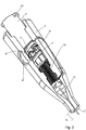
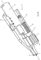
- Fig. 1 shows a first embodiment of an attachment 1 according to the invention with a proximal part 2, which carries a cannula 3, and with a distal part 4.
- the cannula 3 is axially guided through the entire proximal part and protrudes on its distal side.
- the distal part 4 surrounds the proximal part 2 and in particular also the cannula 3 at least in sections, that is to say over at least a partial circumference and / or a partial length measured in the axial direction.
- the proximal part 2 comprises a spiral groove 5 into which two guide tips or pins 6 and 7 of the distal part 4 engage.
- the spiral groove 5 extends over a total length d 2 of a base body of the proximal part 2 with the axial extension d 1 and enables the cannula 3 to be moved out by a length d 3 when the guide tips 6 and 7 slide in the spiral groove 5, see Fig. 2 ,
- the scale is designed in such a way that an indication of the respective penetration depth can be read through the magnifying lens 8 as information.
- the ratio of d 2 to d 1 is 40%.
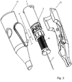
- a lamella 15 is arranged on the distal part 4, the tip 16 of which engages in the spaces 14 between the teeth 13. If the distal part 4 is rotated relative to the proximal part 2, the metal lamella 15 is bent elastically until its tip 16 leaves an intermediate space 14 and engages in the next, adjacent intermediate space 14.
- the in the Fig. 1 and 2 partially visible end face 17 can be flat or concave or convex, whereby even with a curvature a relatively small angle of less than 15 ° is provided at the edge relative to the area around the exit point of the cannula 3.
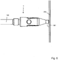
- the syringe 100 with the attachment 1 can be placed in a stable manner at an angle of 90 ° or deviate slightly from an angle a that is at most 45 ° from 90 °.
- the Fig. 8 shows a section of the proximal part with a locking button 18, which belongs to the distal part, the rest of which in Fig. 8 is not shown.
- a locking projection 19 can be released, which can engage in a recess 20 of a plate 21.
- the in Fig. 9 shown release position can be achieved and the distal part 4 are rotated relative to the proximal part 2 to extend the cannula.
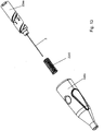
- Fig. 12 shows a second, not claimed embodiment of an attachment 1a, in which the proximal part 2a has recesses 24 in the area of its groove 5a, which are triangular, so that there is a sequence of teeth 23 into which the guide tip 6 can snap.
- the latching option is thus predetermined by the groove 5a itself.
- the cylindrical body 10 with the ring gear is no longer required, and instead a spring element 25 is provided which is supported on an annular seat 26 of the distal part 4a.
- Fig. 13 shows this embodiment in an exploded view.
- the attachment 1 can be connected to a syringe or can instead be integrated into an ultrasound head for observing the location where the syringe is to be inserted.
- Fig. 16 is a dosing regulator attachment for a syringe combined with attachment 1 or 1b according to one of the embodiments of the inventions.
- the distal part 4 or 4a, 4b can be made of very soft plastic, which enables the distal part to be compressed and the proximal part 2, 2a, 2b to be held immediately.
- the cylindrical jacket 34 is preferably transparent in the region of the end face 17, so that the end of the cannula 3 can also be seen during the spraying process.
- the cannula 3 is suitably bevelled, compare for example as in Fig. 14 seen to facilitate precise placement of the cannula in or under the skin or facial skin of a human patient and then further into a facial muscle, subcutis or other organ or tissue.
Landscapes
- Health & Medical Sciences (AREA)
- Life Sciences & Earth Sciences (AREA)
- Veterinary Medicine (AREA)
- Public Health (AREA)
- General Health & Medical Sciences (AREA)
- Animal Behavior & Ethology (AREA)
- Engineering & Computer Science (AREA)
- Heart & Thoracic Surgery (AREA)
- Hematology (AREA)
- Biomedical Technology (AREA)
- Anesthesiology (AREA)
- Vascular Medicine (AREA)
- Medicinal Chemistry (AREA)
- Chemical & Material Sciences (AREA)
- Pharmacology & Pharmacy (AREA)
- Epidemiology (AREA)
- Gastroenterology & Hepatology (AREA)
- Bioinformatics & Cheminformatics (AREA)
- Immunology (AREA)
- Proteomics, Peptides & Aminoacids (AREA)
- Dermatology (AREA)
- Infusion, Injection, And Reservoir Apparatuses (AREA)
Claims (21)
- Élément rapporté (1, 1a) pour ou sur un dispositif (100) pour injecter un liquide dans ou sous la peau (200), dans lequel l'élément rapporté (1, 1a) présente : une partie proximale (2, 2a) qui peut être couplée ou reliée au dispositif (100) et qui porte une canule (3), une partie distale (4, 4a) qui entoure la canule (3) au moins par sections, et dans lequel la partie proximale (2, 4a) et la partie distale (4, 4a) sont mobiles en rotation l'une par rapport à l'autre de telle sorte qu'une étendue (d3) de la saillie de la canule (3) de la partie distale (4, 4a) est variable, dans lequel un nombre discret de positions d'arrêt par rapport au mouvement rotatif est prévu, auxquelles correspond une étendue différente de la saillie de la canule (3) de la partie distale (4, 4a), caractérisé en ce que l'élément rapporté présente un mécanisme de verrouillage (10) avec une couronne dentée formée de dents (13) s'étendant axialement avec des rainures (14) s'étendant axialement entre elles et avec un élément d'encliquetage élastique (15) qui s'engage dans une position encliquetée dans une des rainures (14) pour fournir le nombre distinct de positions d'arrêt par une pluralité de positions encliquetées.
- Élément rapporté (1) selon la revendication 1, caractérisé en ce que les positions encliquetées, lorsque la partie distale (4, 4a) est tournée dans le même sens de rotation, sont traversées successivement, et dans ce cas, l'étendue (d3) de la saillie de la canule (3) augmente ou diminue de manière continue.
- Élément rapporté (1) selon la revendication 2, caractérisé en ce que l'élément d'encliquetage élastique (15) est réalisé sous forme d'une lamelle.
- Élément rapporté (1) selon la revendication 3, caractérisé en ce que la couronne dentée (13) est formée sur la partie proximale (2) et est disposée plus près de la canule (3) qu'un filetage (5) qui permet le mouvement rotatif de la partie distale (4) par rapport à la partie proximale (2).
- Élément rapporté (1) selon la revendication 3, caractérisé en ce que la couronne dentée est formée sur une face intérieure de la partie distale.
- Élément rapporté (1, 1a) selon l'une des revendications 1 à 5, caractérisé en ce qu'une rainure hélicoïdale (5, 5a), dans laquelle s'engage la partie distale (4, 4a), est prévue à l'extérieur de la partie proximale (2, 2a).
- Élément rapporté (1) selon la revendication 6, lorsqu'elle dépend de la revendication 5, caractérisé en ce que la partie distale (4) et la partie proximale (2) présente chacune une section transversale circulaire, en ce que la couronne dentée (13) a une extension radiale maximale qui est inférieure à la distance radiale d'une base de la rainure hélicoïdale (5) du centre de la section transversale circulaire.
- Élément rapporté (1, 1a) selon la revendication 6 ou la revendication 7, caractérisé en ce qu'entre différentes sections de la rainure hélicoïdale (5, 5a) est disposée une section (9) portant des informations, avec au moins un élément d'un nombre, d'une lettre, d'un symbole, d'une ligne de graduation, d'une valeur de gris sur une échelle de gris ou d'une couleur sur une gamme de couleurs, ou avec une combinaison d'un ou plusieurs de ces éléments.
- Élément rapporté selon l'une des revendications 1 à 5, caractérisé en ce que, dans une cavité de la partie proximale ouverte axialement vers le côté distal, un filet intérieur est formé dans lequel une tige de la partie distale s'engage.
- Élément rapporté selon la revendication 1, caractérisé en ce qu'une pluralité de dents avec des espaces est prévue dans lesquels s'engage un élément d'encliquetage élastique, dans lequel l'élément d'encliquetage, lorsqu'il prend une position encliquetée, est mobile élastiquement dans la direction axiale.
- Élément rapporté (1a) selon la revendication 1, caractérisé en ce qu'une rainure hélicoïdale (5a), dans laquelle s'engage la partie distale (4a), est prévue à l'extérieur de la partie proximale (2a), dans lequel des renfoncements d'encliquetage (24) sont formés sur ou dans la rainure hélicoïdale (5a).
- Élément rapporté (1) selon l'une des revendications précédentes, caractérisé par un moyen (18, 18a) sur la partie distale (4) à l'aide duquel elle peut être fixée à la partie proximale (2) dans une position prédéterminée dans laquelle la canule (3) ne dépasse pas du tout de la partie distale (4) pour fournir une protection contre les piqûres d'aiguilles avant l'injection lorsque le dispositif (100) pour l'injection est monté ou après rétraction de la canule ou lorsque le dispositif (100) pour l'injection est changé.
- Élément rapporté (1, 1a, 1b) selon l'une des revendications précédentes, caractérisé en ce que la partie distale (4, 4a, 4b) comprend au moins une partie d'un matériau élastiquement flexible, de sorte que la partie distale (4, 4a, 4b) peut être comprimée par un utilisateur dans une mesure telle que la partie proximale puisse être saisie.
- Élément rapporté (1, 1a, 1b) selon l'une des revendications précédentes, caractérisé en ce que la partie distale (4, 4a, 4b) présente une face frontale (17) plate ou courbe, de préférence convexe dans son ensemble ou concave dans son ensemble.
- Élément rapporté (1, 1a, 1b) selon l'une des revendications 1 à 13, caractérisé en ce que la partie distale (4, 4a, 4b) est conique à son extrémité distale.
- Élément rapporté (1, 1a, 1b) selon l'une des revendications précédentes, caractérisé en ce que la partie distale est au moins partiellement transparente à au moins son extrémité distale (34).
- Élément rapporté (1, 1a, 1b) selon l'une des revendications précédentes, caractérisé en ce qu'une fenêtre transparente, une loupe (7), une ouverture ou un affichage à commande électrique sont prévus dans ou sur la partie distale (4, 4a, 4b).
- Élément rapporté (1, 1a, 1b) selon l'une des revendications 1 à 17, caractérisé en ce que l'élément rapporté (1, 1a, 1b) présente sur sa partie proximale (2, 2a, 2b) un embrayage (33) pour l'accouplement au dispositif (100) pour injecter un liquide, en particulier sous la forme d'un cône pour accoupler une seringue ou un raccord de tuyau.
- Élément rapporté selon l'une des revendications 1 à 17, caractérisé en ce que l'élément rapporté est solidaire du dispositif d'injection d'un liquide.
- Élément rapporté selon l'une des revendications 1 à 17, caractérisé en ce que l'élément rapporté est intégré dans une tête à ultrasons pour un appareil à ultrasons ou d'un appareil à ultrasons.
- Élément rapporté selon l'une des revendications 1 à 17, caractérisé en ce que l'élément rapporté est formé dans ou sur un élément rapporté de contrôleur de dosage pour un dispositif d'injection sur le liquide.
Applications Claiming Priority (2)
| Application Number | Priority Date | Filing Date | Title |
|---|---|---|---|
| DE102015107613.6A DE102015107613A1 (de) | 2015-05-13 | 2015-05-13 | Aufsatz für eine oder an einer Vorrichtung zum Injizieren einer Flüssigkeit in oder unter die Haut |
| PCT/EP2016/060692 WO2016180924A1 (fr) | 2015-05-13 | 2016-05-12 | Élément rapporté pour un dispositif ou destiné à être placé sur ledit dispositif pour l'injection d'un liquide dans ou sous la peau |
Publications (2)
| Publication Number | Publication Date |
|---|---|
| EP3294387A1 EP3294387A1 (fr) | 2018-03-21 |
| EP3294387B1 true EP3294387B1 (fr) | 2020-02-05 |
Family
ID=55969147
Family Applications (1)
| Application Number | Title | Priority Date | Filing Date |
|---|---|---|---|
| EP16722653.9A Active EP3294387B1 (fr) | 2015-05-13 | 2016-05-12 | Élément rapporté pour un dispositif ou destiné à être placé sur ledit dispositif pour l'injection d'un liquide dans ou sous la peau |
Country Status (6)
| Country | Link |
|---|---|
| US (1) | US20180264206A1 (fr) |
| EP (1) | EP3294387B1 (fr) |
| CN (1) | CN107921223A (fr) |
| DE (1) | DE102015107613A1 (fr) |
| ES (1) | ES2785567T3 (fr) |
| WO (1) | WO2016180924A1 (fr) |
Families Citing this family (1)
| Publication number | Priority date | Publication date | Assignee | Title |
|---|---|---|---|---|
| MX2022004645A (es) * | 2019-10-16 | 2022-10-18 | Idevax | Adaptador de aguja y conjunto para formar dispositivo de inyeccion para administrar un fluido a un sujeto. |
Family Cites Families (17)
| Publication number | Priority date | Publication date | Assignee | Title |
|---|---|---|---|---|
| DE7242473U (de) | 1972-11-18 | 1973-02-15 | Haselmeier W | Stichtiefeneinstellung zu einem injektor fuer diabetiker |
| US4356822A (en) * | 1980-10-17 | 1982-11-02 | Winstead Hall Deborah | Syringe assembly |
| DE3715258C2 (de) * | 1987-05-08 | 1996-10-31 | Haselmeier Wilhelm Fa | Injektionsgerät |
| FR2762790B1 (fr) | 1997-05-05 | 1999-08-13 | Stephane Dreystadt | Systeme d'injection a longueur d'aiguille variable |
| US5944700A (en) * | 1997-09-26 | 1999-08-31 | Becton, Dickinson And Company | Adjustable injection length pen needle |
| US6482176B1 (en) * | 1997-11-27 | 2002-11-19 | Disetronic Licensing Ag | Method and device for controlling the introduction depth of an injection needle |
| US20010047151A1 (en) | 2000-02-02 | 2001-11-29 | Yongming Xian | Depth controller for epidural needle |
| DE20013579U1 (de) | 2000-08-08 | 2001-03-29 | Adamaszek, Franz-Heinz, 70193 Stuttgart | Dosier- und automatisches Injektionsgerät |
| NZ554828A (en) * | 2004-12-06 | 2010-07-30 | Washington Biotech Corp | Medicine injection devices and methods |
| KR20090008677U (ko) | 2008-02-25 | 2009-08-28 | 최재영 | 주사기 바늘의 노출길이 조절기구 |
| KR101106495B1 (ko) * | 2009-01-14 | 2012-01-20 | 방시열 | 주사바늘길이조절용관조립체 |
| DE202010000846U1 (de) * | 2010-01-13 | 2010-04-15 | Dieter Hölzle Technik-Projekte GmbH | Einstechtiefeneinstellung |
| DE102010001506A1 (de) | 2010-02-02 | 2011-08-04 | Vosseler, Michael, 78073 | Dermale Zugangsvorrichtung |
| EP2571554B1 (fr) * | 2010-05-17 | 2021-02-17 | Becton, Dickinson and Company | Ensemble aiguille avec ajustement de la profondeur d'injection de l'aiguille |
| IT1401642B1 (it) | 2010-08-31 | 2013-08-02 | Offidani | Dispositivo iniettivo per siringhe intradermiche. |
| ITMO20120040A1 (it) | 2012-02-16 | 2013-08-17 | Lameplast Spa | Dispositivo per il controllo della profondita' di penetrazione di un ago per iniezioni |
| PL234202B1 (pl) * | 2013-09-30 | 2020-01-31 | Htl Strefa Spolka Akcyjna | Urządzenie igły bezpiecznej |
-
2015
- 2015-05-13 DE DE102015107613.6A patent/DE102015107613A1/de not_active Withdrawn
-
2016
- 2016-05-12 EP EP16722653.9A patent/EP3294387B1/fr active Active
- 2016-05-12 WO PCT/EP2016/060692 patent/WO2016180924A1/fr not_active Ceased
- 2016-05-12 CN CN201680039791.6A patent/CN107921223A/zh active Pending
- 2016-05-12 ES ES16722653T patent/ES2785567T3/es active Active
- 2016-05-12 US US15/572,827 patent/US20180264206A1/en not_active Abandoned
Non-Patent Citations (1)
| Title |
|---|
| None * |
Also Published As
| Publication number | Publication date |
|---|---|
| ES2785567T3 (es) | 2020-10-07 |
| DE102015107613A1 (de) | 2016-11-17 |
| WO2016180924A1 (fr) | 2016-11-17 |
| US20180264206A1 (en) | 2018-09-20 |
| CN107921223A (zh) | 2018-04-17 |
| EP3294387A1 (fr) | 2018-03-21 |
Similar Documents
| Publication | Publication Date | Title |
|---|---|---|
| DE69526893T2 (de) | Stiftförmige Vorrichtung zur Verabreichung von Medikamenten mit unterschiedlich inkrementierter Dosierskala | |
| DE60127387T2 (de) | Verstellbare spitze für lanzettenvorrichtung | |
| DE69214670T2 (de) | Automatische, stiftförmige spritze | |
| DE69330374T2 (de) | Injektor und dessen anwendung | |
| EP1970084B1 (fr) | Dispositif d'insertion pour une tête d'insertion, en particulier pour un ensemble d'infusion | |
| EP0565970B1 (fr) | Dispositif pour le prélèvement de sang destiné à un but diagnostique | |
| EP0581788B1 (fr) | Dispositif d'injection | |
| EP1032445B1 (fr) | Procede et dispositif de commande de la profondeur de penetration d'une aiguille pour injection | |
| DE69711139T2 (de) | Nadelvorrichtung mit einhändig aktiviertem Nadelschutz | |
| DE60308042T2 (de) | Stiftförmige medikamentenspritze | |
| DE68907690T2 (de) | Schutzvorrichtung für medizinische Nadeln. | |
| DE69812542T2 (de) | Sicherheitseinwegspritze | |
| DE69812588T2 (de) | Medizinischer injektor | |
| EP0525525A1 (fr) | Injecteur | |
| EP1711218A2 (fr) | Dispositif d'injection a element de dosage enclenchable | |
| DE3638984A1 (de) | Injektionsgeraet | |
| EP2413799B1 (fr) | Dispositif à lancette à réglage de la profondeur d'une piqûre | |
| WO2007140632A1 (fr) | Système d'introduction de liquide dans l'organisme d'un patient | |
| DE102004025651A1 (de) | Vorrichtung zum schmerzfreien Eindringen eines Stechmittels in ein Gewebe | |
| EP2078535A1 (fr) | Seringue pour implant | |
| DE102019005101A1 (de) | Haltevorrichtung zum Betätigen einer Spritze | |
| EP3294387B1 (fr) | Élément rapporté pour un dispositif ou destiné à être placé sur ledit dispositif pour l'injection d'un liquide dans ou sous la peau | |
| EP1419748A1 (fr) | Dispositif d'injection de lentille avec bague | |
| DE10297813B4 (de) | Vorrichtung, die den Schmerz des Einstichs einer Spritze in eine tolerierbare Sinnesempfindung umwandelt | |
| DE19732909A1 (de) | Dosierbare Spritze |
Legal Events
| Date | Code | Title | Description |
|---|---|---|---|
| STAA | Information on the status of an ep patent application or granted ep patent |
Free format text: STATUS: THE INTERNATIONAL PUBLICATION HAS BEEN MADE |
|
| PUAI | Public reference made under article 153(3) epc to a published international application that has entered the european phase |
Free format text: ORIGINAL CODE: 0009012 |
|
| STAA | Information on the status of an ep patent application or granted ep patent |
Free format text: STATUS: REQUEST FOR EXAMINATION WAS MADE |
|
| 17P | Request for examination filed |
Effective date: 20171115 |
|
| AK | Designated contracting states |
Kind code of ref document: A1 Designated state(s): AL AT BE BG CH CY CZ DE DK EE ES FI FR GB GR HR HU IE IS IT LI LT LU LV MC MK MT NL NO PL PT RO RS SE SI SK SM TR |
|
| AX | Request for extension of the european patent |
Extension state: BA ME |
|
| DAV | Request for validation of the european patent (deleted) | ||
| DAX | Request for extension of the european patent (deleted) | ||
| GRAP | Despatch of communication of intention to grant a patent |
Free format text: ORIGINAL CODE: EPIDOSNIGR1 |
|
| STAA | Information on the status of an ep patent application or granted ep patent |
Free format text: STATUS: GRANT OF PATENT IS INTENDED |
|
| RIC1 | Information provided on ipc code assigned before grant |
Ipc: A61K 38/48 20060101ALI20190705BHEP Ipc: A61K 9/00 20060101ALI20190705BHEP Ipc: A61M 5/46 20060101AFI20190705BHEP Ipc: A61M 5/34 20060101ALI20190705BHEP |
|
| INTG | Intention to grant announced |
Effective date: 20190813 |
|
| GRAS | Grant fee paid |
Free format text: ORIGINAL CODE: EPIDOSNIGR3 |
|
| GRAA | (expected) grant |
Free format text: ORIGINAL CODE: 0009210 |
|
| STAA | Information on the status of an ep patent application or granted ep patent |
Free format text: STATUS: THE PATENT HAS BEEN GRANTED |
|
| AK | Designated contracting states |
Kind code of ref document: B1 Designated state(s): AL AT BE BG CH CY CZ DE DK EE ES FI FR GB GR HR HU IE IS IT LI LT LU LV MC MK MT NL NO PL PT RO RS SE SI SK SM TR |
|
| REG | Reference to a national code |
Ref country code: GB Ref legal event code: FG4D Free format text: NOT ENGLISH |
|
| REG | Reference to a national code |
Ref country code: AT Ref legal event code: REF Ref document number: 1229478 Country of ref document: AT Kind code of ref document: T Effective date: 20200215 |
|
| REG | Reference to a national code |
Ref country code: DE Ref legal event code: R096 Ref document number: 502016008624 Country of ref document: DE |
|
| REG | Reference to a national code |
Ref country code: IE Ref legal event code: FG4D Free format text: LANGUAGE OF EP DOCUMENT: GERMAN |
|
| REG | Reference to a national code |
Ref country code: CH Ref legal event code: EP |
|
| REG | Reference to a national code |
Ref country code: CH Ref legal event code: NV Representative=s name: HEPP WENGER RYFFEL AG, CH |
|
| REG | Reference to a national code |
Ref country code: NL Ref legal event code: FP |
|
| PG25 | Lapsed in a contracting state [announced via postgrant information from national office to epo] |
Ref country code: FI Free format text: LAPSE BECAUSE OF FAILURE TO SUBMIT A TRANSLATION OF THE DESCRIPTION OR TO PAY THE FEE WITHIN THE PRESCRIBED TIME-LIMIT Effective date: 20200205 Ref country code: NO Free format text: LAPSE BECAUSE OF FAILURE TO SUBMIT A TRANSLATION OF THE DESCRIPTION OR TO PAY THE FEE WITHIN THE PRESCRIBED TIME-LIMIT Effective date: 20200505 Ref country code: PT Free format text: LAPSE BECAUSE OF FAILURE TO SUBMIT A TRANSLATION OF THE DESCRIPTION OR TO PAY THE FEE WITHIN THE PRESCRIBED TIME-LIMIT Effective date: 20200628 Ref country code: RS Free format text: LAPSE BECAUSE OF FAILURE TO SUBMIT A TRANSLATION OF THE DESCRIPTION OR TO PAY THE FEE WITHIN THE PRESCRIBED TIME-LIMIT Effective date: 20200205 |
|
| REG | Reference to a national code |
Ref country code: LT Ref legal event code: MG4D |
|
| PG25 | Lapsed in a contracting state [announced via postgrant information from national office to epo] |
Ref country code: GR Free format text: LAPSE BECAUSE OF FAILURE TO SUBMIT A TRANSLATION OF THE DESCRIPTION OR TO PAY THE FEE WITHIN THE PRESCRIBED TIME-LIMIT Effective date: 20200506 Ref country code: BG Free format text: LAPSE BECAUSE OF FAILURE TO SUBMIT A TRANSLATION OF THE DESCRIPTION OR TO PAY THE FEE WITHIN THE PRESCRIBED TIME-LIMIT Effective date: 20200505 Ref country code: HR Free format text: LAPSE BECAUSE OF FAILURE TO SUBMIT A TRANSLATION OF THE DESCRIPTION OR TO PAY THE FEE WITHIN THE PRESCRIBED TIME-LIMIT Effective date: 20200205 Ref country code: IS Free format text: LAPSE BECAUSE OF FAILURE TO SUBMIT A TRANSLATION OF THE DESCRIPTION OR TO PAY THE FEE WITHIN THE PRESCRIBED TIME-LIMIT Effective date: 20200605 Ref country code: SE Free format text: LAPSE BECAUSE OF FAILURE TO SUBMIT A TRANSLATION OF THE DESCRIPTION OR TO PAY THE FEE WITHIN THE PRESCRIBED TIME-LIMIT Effective date: 20200205 Ref country code: LV Free format text: LAPSE BECAUSE OF FAILURE TO SUBMIT A TRANSLATION OF THE DESCRIPTION OR TO PAY THE FEE WITHIN THE PRESCRIBED TIME-LIMIT Effective date: 20200205 |
|
| REG | Reference to a national code |
Ref country code: ES Ref legal event code: FG2A Ref document number: 2785567 Country of ref document: ES Kind code of ref document: T3 Effective date: 20201007 |
|
| PG25 | Lapsed in a contracting state [announced via postgrant information from national office to epo] |
Ref country code: CZ Free format text: LAPSE BECAUSE OF FAILURE TO SUBMIT A TRANSLATION OF THE DESCRIPTION OR TO PAY THE FEE WITHIN THE PRESCRIBED TIME-LIMIT Effective date: 20200205 Ref country code: SK Free format text: LAPSE BECAUSE OF FAILURE TO SUBMIT A TRANSLATION OF THE DESCRIPTION OR TO PAY THE FEE WITHIN THE PRESCRIBED TIME-LIMIT Effective date: 20200205 Ref country code: LT Free format text: LAPSE BECAUSE OF FAILURE TO SUBMIT A TRANSLATION OF THE DESCRIPTION OR TO PAY THE FEE WITHIN THE PRESCRIBED TIME-LIMIT Effective date: 20200205 Ref country code: RO Free format text: LAPSE BECAUSE OF FAILURE TO SUBMIT A TRANSLATION OF THE DESCRIPTION OR TO PAY THE FEE WITHIN THE PRESCRIBED TIME-LIMIT Effective date: 20200205 Ref country code: DK Free format text: LAPSE BECAUSE OF FAILURE TO SUBMIT A TRANSLATION OF THE DESCRIPTION OR TO PAY THE FEE WITHIN THE PRESCRIBED TIME-LIMIT Effective date: 20200205 Ref country code: EE Free format text: LAPSE BECAUSE OF FAILURE TO SUBMIT A TRANSLATION OF THE DESCRIPTION OR TO PAY THE FEE WITHIN THE PRESCRIBED TIME-LIMIT Effective date: 20200205 Ref country code: SM Free format text: LAPSE BECAUSE OF FAILURE TO SUBMIT A TRANSLATION OF THE DESCRIPTION OR TO PAY THE FEE WITHIN THE PRESCRIBED TIME-LIMIT Effective date: 20200205 |
|
| REG | Reference to a national code |
Ref country code: DE Ref legal event code: R097 Ref document number: 502016008624 Country of ref document: DE |
|
| PLBE | No opposition filed within time limit |
Free format text: ORIGINAL CODE: 0009261 |
|
| STAA | Information on the status of an ep patent application or granted ep patent |
Free format text: STATUS: NO OPPOSITION FILED WITHIN TIME LIMIT |
|
| 26N | No opposition filed |
Effective date: 20201106 |
|
| PG25 | Lapsed in a contracting state [announced via postgrant information from national office to epo] |
Ref country code: MC Free format text: LAPSE BECAUSE OF FAILURE TO SUBMIT A TRANSLATION OF THE DESCRIPTION OR TO PAY THE FEE WITHIN THE PRESCRIBED TIME-LIMIT Effective date: 20200205 |
|
| PG25 | Lapsed in a contracting state [announced via postgrant information from national office to epo] |
Ref country code: PL Free format text: LAPSE BECAUSE OF FAILURE TO SUBMIT A TRANSLATION OF THE DESCRIPTION OR TO PAY THE FEE WITHIN THE PRESCRIBED TIME-LIMIT Effective date: 20200205 Ref country code: SI Free format text: LAPSE BECAUSE OF FAILURE TO SUBMIT A TRANSLATION OF THE DESCRIPTION OR TO PAY THE FEE WITHIN THE PRESCRIBED TIME-LIMIT Effective date: 20200205 |
|
| PG25 | Lapsed in a contracting state [announced via postgrant information from national office to epo] |
Ref country code: LU Free format text: LAPSE BECAUSE OF NON-PAYMENT OF DUE FEES Effective date: 20200512 |
|
| PG25 | Lapsed in a contracting state [announced via postgrant information from national office to epo] |
Ref country code: IE Free format text: LAPSE BECAUSE OF NON-PAYMENT OF DUE FEES Effective date: 20200512 |
|
| PGFP | Annual fee paid to national office [announced via postgrant information from national office to epo] |
Ref country code: FR Payment date: 20210528 Year of fee payment: 6 Ref country code: NL Payment date: 20210601 Year of fee payment: 6 Ref country code: IT Payment date: 20210526 Year of fee payment: 6 |
|
| PGFP | Annual fee paid to national office [announced via postgrant information from national office to epo] |
Ref country code: AT Payment date: 20210527 Year of fee payment: 6 Ref country code: BE Payment date: 20210527 Year of fee payment: 6 Ref country code: CH Payment date: 20210623 Year of fee payment: 6 Ref country code: ES Payment date: 20210618 Year of fee payment: 6 Ref country code: GB Payment date: 20210528 Year of fee payment: 6 |
|
| PGFP | Annual fee paid to national office [announced via postgrant information from national office to epo] |
Ref country code: DE Payment date: 20210527 Year of fee payment: 6 |
|
| PG25 | Lapsed in a contracting state [announced via postgrant information from national office to epo] |
Ref country code: TR Free format text: LAPSE BECAUSE OF FAILURE TO SUBMIT A TRANSLATION OF THE DESCRIPTION OR TO PAY THE FEE WITHIN THE PRESCRIBED TIME-LIMIT Effective date: 20200205 Ref country code: MT Free format text: LAPSE BECAUSE OF FAILURE TO SUBMIT A TRANSLATION OF THE DESCRIPTION OR TO PAY THE FEE WITHIN THE PRESCRIBED TIME-LIMIT Effective date: 20200205 Ref country code: CY Free format text: LAPSE BECAUSE OF FAILURE TO SUBMIT A TRANSLATION OF THE DESCRIPTION OR TO PAY THE FEE WITHIN THE PRESCRIBED TIME-LIMIT Effective date: 20200205 |
|
| PG25 | Lapsed in a contracting state [announced via postgrant information from national office to epo] |
Ref country code: MK Free format text: LAPSE BECAUSE OF FAILURE TO SUBMIT A TRANSLATION OF THE DESCRIPTION OR TO PAY THE FEE WITHIN THE PRESCRIBED TIME-LIMIT Effective date: 20200205 Ref country code: AL Free format text: LAPSE BECAUSE OF FAILURE TO SUBMIT A TRANSLATION OF THE DESCRIPTION OR TO PAY THE FEE WITHIN THE PRESCRIBED TIME-LIMIT Effective date: 20200205 |
|
| REG | Reference to a national code |
Ref country code: DE Ref legal event code: R119 Ref document number: 502016008624 Country of ref document: DE |
|
| REG | Reference to a national code |
Ref country code: CH Ref legal event code: PL |
|
| REG | Reference to a national code |
Ref country code: NL Ref legal event code: MM Effective date: 20220601 |
|
| REG | Reference to a national code |
Ref country code: AT Ref legal event code: MM01 Ref document number: 1229478 Country of ref document: AT Kind code of ref document: T Effective date: 20220512 |
|
| REG | Reference to a national code |
Ref country code: BE Ref legal event code: MM Effective date: 20220531 |
|
| GBPC | Gb: european patent ceased through non-payment of renewal fee |
Effective date: 20220512 |
|
| PG25 | Lapsed in a contracting state [announced via postgrant information from national office to epo] |
Ref country code: LI Free format text: LAPSE BECAUSE OF NON-PAYMENT OF DUE FEES Effective date: 20220531 Ref country code: CH Free format text: LAPSE BECAUSE OF NON-PAYMENT OF DUE FEES Effective date: 20220531 Ref country code: AT Free format text: LAPSE BECAUSE OF NON-PAYMENT OF DUE FEES Effective date: 20220512 |
|
| PG25 | Lapsed in a contracting state [announced via postgrant information from national office to epo] |
Ref country code: FR Free format text: LAPSE BECAUSE OF NON-PAYMENT OF DUE FEES Effective date: 20220531 |
|
| PG25 | Lapsed in a contracting state [announced via postgrant information from national office to epo] |
Ref country code: GB Free format text: LAPSE BECAUSE OF NON-PAYMENT OF DUE FEES Effective date: 20220512 Ref country code: DE Free format text: LAPSE BECAUSE OF NON-PAYMENT OF DUE FEES Effective date: 20221201 Ref country code: BE Free format text: LAPSE BECAUSE OF NON-PAYMENT OF DUE FEES Effective date: 20220531 |
|
| REG | Reference to a national code |
Ref country code: ES Ref legal event code: FD2A Effective date: 20230628 |
|
| PG25 | Lapsed in a contracting state [announced via postgrant information from national office to epo] |
Ref country code: NL Free format text: LAPSE BECAUSE OF NON-PAYMENT OF DUE FEES Effective date: 20220601 |
|
| PG25 | Lapsed in a contracting state [announced via postgrant information from national office to epo] |
Ref country code: IT Free format text: LAPSE BECAUSE OF NON-PAYMENT OF DUE FEES Effective date: 20220512 Ref country code: ES Free format text: LAPSE BECAUSE OF NON-PAYMENT OF DUE FEES Effective date: 20220513 |