EP3294460B1 - Séparateur à cyclone et gazéificateur à lit fixe pour produire un gaz à partir de matières de charge carbonées à l'aide d'un tel séparateur à cyclone - Google Patents
Séparateur à cyclone et gazéificateur à lit fixe pour produire un gaz à partir de matières de charge carbonées à l'aide d'un tel séparateur à cyclone Download PDFInfo
- Publication number
- EP3294460B1 EP3294460B1 EP16723981.3A EP16723981A EP3294460B1 EP 3294460 B1 EP3294460 B1 EP 3294460B1 EP 16723981 A EP16723981 A EP 16723981A EP 3294460 B1 EP3294460 B1 EP 3294460B1
- Authority
- EP
- European Patent Office
- Prior art keywords
- gasifier
- cyclone separator
- gas inlet
- separation body
- cross
- Prior art date
- Legal status (The legal status is an assumption and is not a legal conclusion. Google has not performed a legal analysis and makes no representation as to the accuracy of the status listed.)
- Not-in-force
Links
Images


Classifications
-
- B—PERFORMING OPERATIONS; TRANSPORTING
- B04—CENTRIFUGAL APPARATUS OR MACHINES FOR CARRYING-OUT PHYSICAL OR CHEMICAL PROCESSES
- B04C—APPARATUS USING FREE VORTEX FLOW, e.g. CYCLONES
- B04C5/00—Apparatus in which the axial direction of the vortex is reversed
- B04C5/02—Construction of inlets by which the vortex flow is generated, e.g. tangential admission, the fluid flow being forced to follow a downward path by spirally wound bulkheads, or with slightly downwardly-directed tangential admission
- B04C5/04—Tangential inlets
-
- B—PERFORMING OPERATIONS; TRANSPORTING
- B04—CENTRIFUGAL APPARATUS OR MACHINES FOR CARRYING-OUT PHYSICAL OR CHEMICAL PROCESSES
- B04C—APPARATUS USING FREE VORTEX FLOW, e.g. CYCLONES
- B04C5/00—Apparatus in which the axial direction of the vortex is reversed
- B04C5/08—Vortex chamber constructions
- B04C5/081—Shapes or dimensions
-
- C—CHEMISTRY; METALLURGY
- C10—PETROLEUM, GAS OR COKE INDUSTRIES; TECHNICAL GASES CONTAINING CARBON MONOXIDE; FUELS; LUBRICANTS; PEAT
- C10B—DESTRUCTIVE DISTILLATION OF CARBONACEOUS MATERIALS FOR PRODUCTION OF GAS, COKE, TAR, OR SIMILAR MATERIALS
- C10B27/00—Arrangements for withdrawal of the distillation gases
-
- C—CHEMISTRY; METALLURGY
- C10—PETROLEUM, GAS OR COKE INDUSTRIES; TECHNICAL GASES CONTAINING CARBON MONOXIDE; FUELS; LUBRICANTS; PEAT
- C10B—DESTRUCTIVE DISTILLATION OF CARBONACEOUS MATERIALS FOR PRODUCTION OF GAS, COKE, TAR, OR SIMILAR MATERIALS
- C10B49/00—Destructive distillation of solid carbonaceous materials by direct heating with heat-carrying agents including the partial combustion of the solid material to be treated
- C10B49/02—Destructive distillation of solid carbonaceous materials by direct heating with heat-carrying agents including the partial combustion of the solid material to be treated with hot gases or vapours, e.g. hot gases obtained by partial combustion of the charge
-
- C—CHEMISTRY; METALLURGY
- C10—PETROLEUM, GAS OR COKE INDUSTRIES; TECHNICAL GASES CONTAINING CARBON MONOXIDE; FUELS; LUBRICANTS; PEAT
- C10B—DESTRUCTIVE DISTILLATION OF CARBONACEOUS MATERIALS FOR PRODUCTION OF GAS, COKE, TAR, OR SIMILAR MATERIALS
- C10B53/00—Destructive distillation, specially adapted for particular solid raw materials or solid raw materials in special form
- C10B53/02—Destructive distillation, specially adapted for particular solid raw materials or solid raw materials in special form of cellulose-containing material
-
- C—CHEMISTRY; METALLURGY
- C10—PETROLEUM, GAS OR COKE INDUSTRIES; TECHNICAL GASES CONTAINING CARBON MONOXIDE; FUELS; LUBRICANTS; PEAT
- C10J—PRODUCTION OF PRODUCER GAS, WATER-GAS, SYNTHESIS GAS FROM SOLID CARBONACEOUS MATERIAL, OR MIXTURES CONTAINING THESE GASES; CARBURETTING AIR OR OTHER GASES
- C10J3/00—Production of combustible gases containing carbon monoxide from solid carbonaceous fuels
- C10J3/02—Fixed-bed gasification of lump fuel
- C10J3/20—Apparatus; Plants
-
- C—CHEMISTRY; METALLURGY
- C10—PETROLEUM, GAS OR COKE INDUSTRIES; TECHNICAL GASES CONTAINING CARBON MONOXIDE; FUELS; LUBRICANTS; PEAT
- C10J—PRODUCTION OF PRODUCER GAS, WATER-GAS, SYNTHESIS GAS FROM SOLID CARBONACEOUS MATERIAL, OR MIXTURES CONTAINING THESE GASES; CARBURETTING AIR OR OTHER GASES
- C10J3/00—Production of combustible gases containing carbon monoxide from solid carbonaceous fuels
- C10J3/02—Fixed-bed gasification of lump fuel
- C10J3/20—Apparatus; Plants
- C10J3/22—Arrangements or dispositions of valves or flues
- C10J3/24—Arrangements or dispositions of valves or flues to permit flow of gases or vapours other than upwardly through the fuel bed
- C10J3/26—Arrangements or dispositions of valves or flues to permit flow of gases or vapours other than upwardly through the fuel bed downwardly
-
- C—CHEMISTRY; METALLURGY
- C10—PETROLEUM, GAS OR COKE INDUSTRIES; TECHNICAL GASES CONTAINING CARBON MONOXIDE; FUELS; LUBRICANTS; PEAT
- C10J—PRODUCTION OF PRODUCER GAS, WATER-GAS, SYNTHESIS GAS FROM SOLID CARBONACEOUS MATERIAL, OR MIXTURES CONTAINING THESE GASES; CARBURETTING AIR OR OTHER GASES
- C10J3/00—Production of combustible gases containing carbon monoxide from solid carbonaceous fuels
- C10J3/02—Fixed-bed gasification of lump fuel
- C10J3/20—Apparatus; Plants
- C10J3/34—Grates; Mechanical ash-removing devices
- C10J3/40—Movable grates
- C10J3/42—Rotary grates
-
- C—CHEMISTRY; METALLURGY
- C10—PETROLEUM, GAS OR COKE INDUSTRIES; TECHNICAL GASES CONTAINING CARBON MONOXIDE; FUELS; LUBRICANTS; PEAT
- C10J—PRODUCTION OF PRODUCER GAS, WATER-GAS, SYNTHESIS GAS FROM SOLID CARBONACEOUS MATERIAL, OR MIXTURES CONTAINING THESE GASES; CARBURETTING AIR OR OTHER GASES
- C10J3/00—Production of combustible gases containing carbon monoxide from solid carbonaceous fuels
- C10J3/72—Other features
- C10J3/723—Controlling or regulating the gasification process
-
- C—CHEMISTRY; METALLURGY
- C10—PETROLEUM, GAS OR COKE INDUSTRIES; TECHNICAL GASES CONTAINING CARBON MONOXIDE; FUELS; LUBRICANTS; PEAT
- C10J—PRODUCTION OF PRODUCER GAS, WATER-GAS, SYNTHESIS GAS FROM SOLID CARBONACEOUS MATERIAL, OR MIXTURES CONTAINING THESE GASES; CARBURETTING AIR OR OTHER GASES
- C10J3/00—Production of combustible gases containing carbon monoxide from solid carbonaceous fuels
- C10J3/72—Other features
- C10J3/82—Gas withdrawal means
- C10J3/84—Gas withdrawal means with means for removing dust or tar from the gas
-
- F—MECHANICAL ENGINEERING; LIGHTING; HEATING; WEAPONS; BLASTING
- F23—COMBUSTION APPARATUS; COMBUSTION PROCESSES
- F23C—METHODS OR APPARATUS FOR COMBUSTION USING FLUID FUEL OR SOLID FUEL SUSPENDED IN A CARRIER GAS OR AIR
- F23C5/00—Disposition of burners with respect to the combustion chamber or to one another; Mounting of burners in combustion apparatus
- F23C5/08—Disposition of burners
- F23C5/32—Disposition of burners to obtain rotating flames, i.e. flames moving helically or spirally
-
- C—CHEMISTRY; METALLURGY
- C10—PETROLEUM, GAS OR COKE INDUSTRIES; TECHNICAL GASES CONTAINING CARBON MONOXIDE; FUELS; LUBRICANTS; PEAT
- C10J—PRODUCTION OF PRODUCER GAS, WATER-GAS, SYNTHESIS GAS FROM SOLID CARBONACEOUS MATERIAL, OR MIXTURES CONTAINING THESE GASES; CARBURETTING AIR OR OTHER GASES
- C10J2200/00—Details of gasification apparatus
- C10J2200/15—Details of feeding means
- C10J2200/152—Nozzles or lances for introducing gas, liquids or suspensions
-
- F—MECHANICAL ENGINEERING; LIGHTING; HEATING; WEAPONS; BLASTING
- F23—COMBUSTION APPARATUS; COMBUSTION PROCESSES
- F23B—METHODS OR APPARATUS FOR COMBUSTION USING ONLY SOLID FUEL
- F23B80/00—Combustion apparatus characterised by means creating a distinct flow path for flue gases or for non-combusted gases given off by the fuel
-
- Y—GENERAL TAGGING OF NEW TECHNOLOGICAL DEVELOPMENTS; GENERAL TAGGING OF CROSS-SECTIONAL TECHNOLOGIES SPANNING OVER SEVERAL SECTIONS OF THE IPC; TECHNICAL SUBJECTS COVERED BY FORMER USPC CROSS-REFERENCE ART COLLECTIONS [XRACs] AND DIGESTS
- Y02—TECHNOLOGIES OR APPLICATIONS FOR MITIGATION OR ADAPTATION AGAINST CLIMATE CHANGE
- Y02E—REDUCTION OF GREENHOUSE GAS [GHG] EMISSIONS, RELATED TO ENERGY GENERATION, TRANSMISSION OR DISTRIBUTION
- Y02E50/00—Technologies for the production of fuel of non-fossil origin
- Y02E50/10—Biofuels, e.g. bio-diesel
Definitions
- the invention relates to a cyclone separator according to the preamble of claim 1 and a fixed bed gasifier for generating a product gas from carbonaceous feedstocks, the product gas outlet of which is followed by such a cyclone separator.
- Fixed bed gasifiers for generating a combustible product gas from biomass pellets, in particular from wood chips or wood pellets are characterized by a comparatively simple structure.
- the direction of flow of the combustion air and the product gas on the one hand and the direction of supply of the biomass particles are opposite, and in the case of the cocurrent gasifier, the direction of supply of the biomass particles corresponds to the direction of flow of the combustion air and product gas.
- reaction zones namely drying, pyrolysis, oxidation and reduction zones, in which different thermochemical reactions take place.
- the drying, pyrolysis, oxidation and reduction zones are formed from top to bottom.
- the oxidation zone forms in the area of the air supply and should remain limited to this zone, the reduction zone below, directly above the grate.
- the product gas is extracted from the area of the gasifier container under the grate, in which the small ash falling through the grate also collects.
- the product gas contains solid particles of different sizes.
- the largest solid particles are usually separated with a downstream cyclone separator.
- a cyclone separator is from DE 4233174 A1 known.
- This known cyclone separator comprises a downwardly conical separating body with a longitudinal axis, a gas outlet dipping into the separating body from above, a particle outlet arranged at the lower end of the separating body and a gas inlet opening into the separating body transversely to the longitudinal axis of the separating body, the gas inlet having a first end and the second end, the second end opening into the separating body, and wherein the gas inlet (16) widens in the axial direction of the separating body and spirally surrounds the separating body.
- the cross-sectional area of the gas inlet remains substantially constant between the first and second ends of the gas inlet. From the DE 825332 B a similar cyclone separator is known in which the cross-sectional area between the first and second ends of the gas inlet increases. It has been found that the particle separation efficiency of these known cyclone separators is inadequate, especially when used for cleaning product gas from fixed-bed gasifiers.
- US 3306461 A1 discloses a cyclone separator for separating solids from liquids, the inlet nozzle of which has a cross-sectional area which decreases in the direction of flow.
- a similar cyclone separator is off WO 2005/021162 A1 known.
- the cyclone separator in U.S. 3,850,816 A has an inlet nozzle which initially becomes continuously narrower in the direction of flow, has a constant cross section in a second section and is continuously widened in a third section.
- WO 2013/124536 A1 describes a gas generator for generating a product gas from fuels, which has a rotatable grate.
- GB 2,481,429 A describes a cyclone separator with at least two separating bodies, a separating plate being built into the gas inlet, which divides the gas flow between the separating bodies.
- Another object of the present invention is to provide a cyclone separator with improved separation properties. Another object of the invention is to provide a fixed bed gasifier for generating a product gas from carbonaceous feedstocks with such a cyclone separator.
- the spiral-shaped widening of the gas inlet improves the particle separation efficiency.
- the widening of the gas inlet supports the formation and maintenance of the eddy flow in the separating body.
- the reduction in cross-section increases the flow rate and thus the efficiency of particle separation.
- the at least one baffle in the gas inlet ensures that the solid particles are distributed over the entire cross section of the gas inlet.
- the particle separation is also improved by the continuous reduction in cross-sectional area according to claim 3.
- the rectilinear section of the gas inlet according to claim 4 achieves a homogeneous particle distribution over the cross section.
- the agglomeration to form larger, more easily separable particles is promoted.
- the sudden expansion of the cross-sectional area according to claim 8 results in changes in the speed of the gas flow which lead to an increased agglomeration of small to larger particles. This improves the particle separation rate. Improved agglomeration is particularly useful in the case of "sticky" particles, e.g. B. coke particles possible.
- the particle separation rate is also increased. It has been found that the particle separation rate drops with larger gas flows and larger separating bodies. The design as a double cyclone compensates for this negative effect.
- the fixed bed gasifier according to claim 10 allows a safe and stable process control and continuously provides a low-tar product gas.
- the air is supplied through the fill of biomass particles in the tubular gasifier component. This results in an even distribution of the air. Due to this uniform distribution, there are hardly any temperature differences in the oxidation zone. As a result, pyrolysis gases, which arise above the oxidation zone, also flow uniformly through the oxidation zone. Due to this uniformity of the gas and air flows, a product gas with small amounts of tar can be generated.
- This configuration is the subject of DE102014225166.4 , the disclosure of which is incorporated by reference in its entirety.
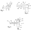
- FIGS 1 to 3 show an exemplary embodiment of a cyclone separator 2 according to the present invention.
- the cyclone separator 1 comprises a downwardly conical separating body 10 which ends through a lock device 12 for discharging the separated solid particles.
- the separating body 10 comprises an upper columnar section 100 with a constant circular cross section.
- a conical section 102, which ends with the lock device 12, is arranged below the columnar section 100.
- a tubular gas outlet 14 protrudes from the columnar section 101, via which the purified gas with a reduced proportion of solid particles is fed.
- the tubular gas outlet 14 extends into the separating body 10 and ends before the conical section 102.
- the gas contaminated with solid particles e.g. B. product gas from a fixed bed gasifier is fed to the separator 10 via a gas inlet 16 extending transversely to the longitudinal axis of the separator 10.
- the gas inlet 16 comprises a first end 161 and a second end 162 and a straight section 166 and a spiral section 167.
- the gas loaded with solid particles enters the gas inlet 16, successively flowing through the straight section 166, the spiral section Section 167 and enters the columnar section 100 of the separating body 10 via the second end 162.
- the First End 161 of the gas inlet 16 has a rectangular cross section with a first cross-sectional area A 1 .
- the gas inlet 16 widens between the first end 161 and the second end 162, so that the largest diameter D of the gas inlet 16 at the second end 162 corresponds approximately to the diameter of the columnar section 100 of the separating body 10.
- the cross-sectional area of the gas inlet 16 decreases continuously to a minimum cross-sectional area A 2 at the second end 162 of the gas inlet 16.
- the ratio of A 2 to A 1 is 0.5 in the exemplary embodiment.
- a straight guide plate 164 is arranged in the flow direction, which ensures that the solid particles are distributed over the widening cross-section of the gas inlet and do not concentrate centrally in the gas flow.
- the gas inlet 16 has an upper edge 168 and a lower edge 169.
- the upper edge 168 runs perpendicular to the longitudinal axis of the separating body 10.
- the lower edge 169 forms an obtuse or acute angle with the longitudinal axis or the vertical.
- Fig. 4 shows an alternative embodiment of a cyclone separator 1 with a separating body 10, the flow direction has two abrupt cross-sectional area extensions 104 immediately in front of the lock device 12. The resulting change in the speed of the gas flow increases the agglomeration of smaller to larger particles. Since larger particles can be separated more easily, the particle separation rate increases.
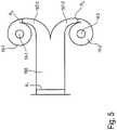
- Fig. 5 shows a further embodiment of the invention in the form of a double cyclone with a common rectilinear section 166, which is divided into a first and a second spiral section 167-1 and 167-2 with opposite directions of rotation, which then into a first and a second separating body 10- 1 and 10-2 flow.
- Fig. 6 shows a schematic representation of an exemplary embodiment of a fixed bed gasifier 2 according to the present invention.
- the fixed bed gasifier 2 comprises a tubular gasifier container 20, the ends of which are closed with an upper cover 22 and a lower cover 24.
- the closed end 262 of the carburetor component 26 protrudes from the carburetor container 20 through the upper cover 22.
- the open end 261 of the carburetor component 26 comes to lie approximately in the middle of the carburetor container 20.
- a rotatable grate 4 is arranged, which can be moved periodically by a motor drive 40 which passes through the lower cover 24.
- an inspection shaft 34 is provided which penetrates the outer wall of the carburetor container 20.
- the inspection shaft 34 is closed by a cover flange 50 which is part of a temperature measuring device 5.
- the temperature in the gasifier container 20 can be monitored by the temperature measuring device 5.
- maintenance work and cleaning work can be carried out inside the reactor vessel via the inspection shaft 34.
- the rotatable grate 4 comprises a disk-shaped main part 42 for supporting the carbon-containing feedstock or the biomass particles.
- the main part 42 is mounted centrally on a rotation axis 44, which passes through the lower cover 24 of the carburetor container 20 and can be set in rotation by the motor drive 40.
- a dome-shaped cover 46 is arranged on the upper side of the main part 42.
- a plurality of slot-shaped openings 48 are provided for the passage of ash and product gas through the main part 42.
- product gas is withdrawn from the gasifier container 20 via a product gas vent 36, cooled in a heat exchanger 38 and purified in a downstream cyclone separator 1.
- the ash falling through the grate 4 is discharged from the fixed-bed gasifier 2 by the product gas flow via the product gas vent 36.
- Both the tubular gasifier container 20 and the tubular gasifier component 26 have an annular cross section and are arranged concentrically to one another.
- the tubular carburetor component 26 has an inner diameter d which is smaller than the inner diameter D of the tubular carburetor container 20.
Landscapes
- Chemical & Material Sciences (AREA)
- Engineering & Computer Science (AREA)
- Oil, Petroleum & Natural Gas (AREA)
- Organic Chemistry (AREA)
- Combustion & Propulsion (AREA)
- Mechanical Engineering (AREA)
- Physics & Mathematics (AREA)
- Materials Engineering (AREA)
- General Chemical & Material Sciences (AREA)
- Chemical Kinetics & Catalysis (AREA)
- Geometry (AREA)
- Fluid Mechanics (AREA)
- General Engineering & Computer Science (AREA)
- Cyclones (AREA)
- Processing Of Solid Wastes (AREA)
- Solid-Fuel Combustion (AREA)
- Devices And Processes Conducted In The Presence Of Fluids And Solid Particles (AREA)
Claims (11)
- Séparateur à cyclone (1) servant à la séparation de particules solides d'un flux de gaz, comportant un corps de séparation (10) se terminant de manière conique vers le bas, lequel présente un axe longitudinal, une sortie de gaz (14) plongeant par le haut dans le corps de séparation (10),une sortie de particules (12) disposée à l'extrémité inférieure du corps de séparation (10), etune entrée de gaz (16) débouchant dans le corps de séparation (10) transversalement à l'axe longitudinal du corps de séparation (10), l'entrée de gaz (16) comprenant une première extrémité (161) et une deuxième extrémité (162), la deuxième extrémité (162) débouchant dans le corps de séparation (10), et l'entrée de gaz (16) s'élargissant dans la direction axiale du corps séparation (10) et enveloppant le corps de séparation en forme de spirale, l'entrée de gaz (16) présentant à la première extrémité (161) une aire en section transversale initiale (A1) qui diminue en direction du corps de séparation (10) jusqu'à une aire en section transversale minimale (A2) à la deuxième extrémité (162),caractérisé en cequ'au moins un déflecteur (164) servant à la répartition des particules solides contenues dans le flux de gaz sur la section transversale s'élargissant de l'entrée de gaz (16) est disposé dans l'entrée de gaz (16).
- Séparateur à cyclone selon la revendication 1, caractérisé en ce que l'aire en section transversale à la deuxième extrémité (A2) vaut entre 30% et 70% et en particulier entre 40% et 60% de l'aire en section transversale initiale (A1).
- Séparateur à cyclone selon l'une des revendications précédentes, caractérisé en ce que l'aire en section transversale (A) de l'entrée de gaz (16) diminue de manière continue.
- Séparateur à cyclone selon l'une des revendications précédentes, caractérisé en ce que l'entrée de gaz (16) comporte une partie (166) s'étendant de manière rectiligne et une partie (167) s'étendant en forme de spirale.
- Séparateur à cyclone selon l'une des revendications précédentes, caractérisé en ce que l'entrée de gaz (16) présente, lors du passage à travers la paroi extérieure du corps de séparation (10), une étendue dans la direction axiale du corps de séparation (10) qui correspond approximativement au plus grand diamètre du corps de séparation (10).
- Séparateur à cyclone selon l'une des revendications précédentes 4 et 5, caractérisé en ce que l'au moins un déflecteur (164) est disposé dans la partie (166) s'étendant de manière rectiligne de l'entrée de gaz (16).
- Séparateur à cyclone selon l'une des revendications précédentes, caractérisé en ce que le bord supérieur de l'entrée de gaz (16) s'étend perpendiculairement à l'axe longitudinal du corps de séparation (10).
- Séparateur à cyclone selon l'une des revendications précédentes, caractérisé en ce qu'au moins un élargissement brusque d'aire en section transversale (104) est prévu dans le corps de séparation (10) avant le dispositif de sas (12).
- Séparateur à cyclone selon l'une des revendications précédentes, caractérisé en ce qu'une partie commune (166) s'étendant de manière rectiligne se prolonge par deux parties (167-1, 167-2) s'étendant en forme de spirale qui débouchent avec des sens d'enroulement opposés dans deux corps de séparation (10-1, 10-2) disposés parallèlement.
- Gazéificateur (2) à lit fixe servant à former un produit gazeux à partir de matières de charge carbonées, en particulier de particules de biomasse, comportant un récipient de gazéification (20),une amenée (28) de matières de charge carbonées dans la région supérieure du récipient de gazéification (20), une grille rotative (4) servant à soutenir les matières de charge carbonées et disposée dans la région inférieure du récipient de gazéification (20),une amenée d'air (30) servant à l'amenée d'air de combustion dans le récipient de gazéification (20), et une extraction (36) de produit gazeux sortant du récipient de gazéification (20) hors de la région en dessous de la grille (4) et servant à l'évacuation du produit gazeux hors du récipient de gazéification (20), caractérisé en ce qu'un séparateur à cyclone (1) selon l'une des revendications précédentes est placé en aval de l'extraction (36) de produit gazeux.
- Gazéificateur à lit fixe selon la revendication 10, caractériséen ce qu'un composant tubulaire (26) du gazéificateur pénètre dans le récipient de gazéification (20),en ce que le composant tubulaire (26) du gazéificateur comprend une extrémité ouverte (261) qui est disposée dans le récipient de gazéification (20),en ce que le composant tubulaire (26) du gazéificateur comprend une extrémité fermée (262) qui fait saillie hors du récipient de gazéification (20) ou se termine par le côté supérieur du récipient de gazéification (20),en ce que le diamètre intérieur (d) du composant tubulaire (26) du gazéificateur est inférieur au diamètre intérieur (D) du récipient de gazéification (20),en ce que le composant tubulaire (26) du gazéificateur est disposé dans le récipient de gazéification (20) de telle sorte qu'il reste une distance (h) entre l'extrémité ouverte (261) du composant tubulaire (26) du gazéificateur et la grille (4),en ce que l'amenée (28) de matières de charge carbonées débouche dans d'extrémité fermée (262) du composant tubulaire (26) du gazéificateur eten ce que l'amenée d'air (30) débouche dans l'extrémité fermée (262) du composant tubulaire (26) du gazéificateur.
Applications Claiming Priority (2)
| Application Number | Priority Date | Filing Date | Title |
|---|---|---|---|
| DE102015208923.1A DE102015208923B4 (de) | 2015-05-13 | 2015-05-13 | Zyklonabscheider sowie Festbettvergaser zum Erzeugen eines Produktgases aus kohlenstoffhaltigen Einsatzstoffen mit einem solchen Zyklonabscheider |
| PCT/EP2016/060356 WO2016180791A1 (fr) | 2015-05-13 | 2016-05-09 | Séparateur à cyclone et gazéificateur à lit fixe pour produire un gaz à partir de matières de charge carbonées à l'aide d'un tel séparateur à cyclone |
Publications (2)
| Publication Number | Publication Date |
|---|---|
| EP3294460A1 EP3294460A1 (fr) | 2018-03-21 |
| EP3294460B1 true EP3294460B1 (fr) | 2021-09-22 |
Family
ID=56026824
Family Applications (2)
| Application Number | Title | Priority Date | Filing Date |
|---|---|---|---|
| EP16724325.2A Active EP3294461B1 (fr) | 2015-05-13 | 2016-05-09 | Gazogène de lit solides avec une grille rotative pour produire un gaz à partir d'un matériau carboné |
| EP16723981.3A Not-in-force EP3294460B1 (fr) | 2015-05-13 | 2016-05-09 | Séparateur à cyclone et gazéificateur à lit fixe pour produire un gaz à partir de matières de charge carbonées à l'aide d'un tel séparateur à cyclone |
Family Applications Before (1)
| Application Number | Title | Priority Date | Filing Date |
|---|---|---|---|
| EP16724325.2A Active EP3294461B1 (fr) | 2015-05-13 | 2016-05-09 | Gazogène de lit solides avec une grille rotative pour produire un gaz à partir d'un matériau carboné |
Country Status (5)
| Country | Link |
|---|---|
| US (2) | US20180085761A1 (fr) |
| EP (2) | EP3294461B1 (fr) |
| DE (1) | DE102015208923B4 (fr) |
| EA (2) | EA201792504A1 (fr) |
| WO (2) | WO2016180793A1 (fr) |
Families Citing this family (12)
| Publication number | Priority date | Publication date | Assignee | Title |
|---|---|---|---|---|
| USD828422S1 (en) * | 2017-01-24 | 2018-09-11 | Superior Industries, Inc. | Hydrocyclone inlet head |
| USD857071S1 (en) * | 2017-01-24 | 2019-08-20 | Superior Industries, Inc. | Hydrocyclone inlet head |
| JP1574166S (fr) | 2016-08-31 | 2020-04-06 | ||
| JP1574165S (fr) * | 2016-08-31 | 2020-04-06 | ||
| CN109735367B (zh) * | 2019-03-11 | 2023-12-29 | 上海电气集团股份有限公司 | 下吸式气化炉 |
| US11713426B2 (en) * | 2020-01-07 | 2023-08-01 | V-Grid Energy Systems, Inc. | Systems for automatic solids flow in a gasifier |
| CN111265147A (zh) * | 2020-03-27 | 2020-06-12 | 爱源(厦门)电子有限公司 | 一种多锥旋风分离器及包括该分离器的集尘装置 |
| CN112410072A (zh) * | 2020-11-04 | 2021-02-26 | 山东义丰环保机械股份有限公司 | 一种生物质煤气发生炉 |
| CN114216125B (zh) * | 2021-11-27 | 2024-08-30 | 安徽昊源化工集团有限公司 | 一种煤化工固体炉渣回收再利用系统 |
| CN114456843B (zh) * | 2022-01-14 | 2023-01-31 | 江苏兴立环保设备有限公司 | 裂解气化炉的侧面出灰装置 |
| US11850605B2 (en) * | 2022-03-01 | 2023-12-26 | Saudi Arabian Oil Company | Apparatus and method to separate and condition multiphase flow |
| AT526670B1 (de) | 2023-03-27 | 2024-06-15 | Polytechnik Luft Und Feuerungstechnik Gmbh | Treppenrost für Festbrennstoff-Gegenstromvergaser |
Family Cites Families (24)
| Publication number | Priority date | Publication date | Assignee | Title |
|---|---|---|---|---|
| US1862477A (en) * | 1926-06-24 | 1932-06-07 | Galusha Albert Leet | Furnace |
| US2147324A (en) * | 1936-01-16 | 1939-02-14 | Koppers Co Inc | Gas producer |
| US2303406A (en) * | 1940-07-02 | 1942-12-01 | Smerling Carl | Combustion apparatus |
| DE825332C (de) * | 1949-11-01 | 1951-12-17 | Pollrich Paul & Co | Fliehkraft-Staubabscheider |
| US3306461A (en) * | 1964-08-18 | 1967-02-28 | Int Minerals & Chem Corp | Hydrocyclone |
| DE2038045C3 (de) * | 1970-07-31 | 1981-12-10 | Siemens AG, 1000 Berlin und 8000 München | Zyklon |
| US4137051A (en) * | 1978-01-06 | 1979-01-30 | General Electric Company | Grate for coal gasifier |
| US4583992A (en) * | 1984-12-04 | 1986-04-22 | Buck Rogers Mfg. Co., Inc. | Biomass gasifier and charcoal producer |
| US5230716A (en) * | 1992-07-14 | 1993-07-27 | The United States Of America As Represented By The United States Department Of Energy | Grate assembly for fixed-bed coal gasifier |
| DE4233174A1 (de) * | 1992-10-02 | 1994-04-07 | Fette Dietrich | Zyklonabscheider |
| JP3426749B2 (ja) * | 1994-12-01 | 2003-07-14 | 三菱重工業株式会社 | 固定床ガス化炉及び有機系廃棄物のガス化法 |
| CL2003001757A1 (es) * | 2003-08-29 | 2005-01-21 | Vulco Sa | Cabezal de entrada para hidrociclon, en el cual la altura del buscador de vortice, es una fraccion de la altura de la entrada de alimentacion, la cual es rectangular, donde dicha entrada tiene un primer sector que forma una voluta horizontal, y un se |
| DE102006001299A1 (de) * | 2006-01-11 | 2007-07-12 | Eckhart Weber | Holzpellet-Blockheizkraftwerk mit Stirlingmotor in Brennwerttechnik |
| US8961626B1 (en) * | 2006-01-25 | 2015-02-24 | Randall J. Thiessen | Rotating and movable bed gasifier |
| FI123850B (fi) * | 2007-04-05 | 2013-11-15 | Pauli Pieti | Rosti |
| US8657892B2 (en) * | 2007-07-05 | 2014-02-25 | The Board Of Regents For Oklahoma State University | Downdraft gasifier with internal cyclonic combustion chamber |
| DE102008013485A1 (de) | 2008-03-10 | 2009-11-05 | Raziol Zibulla & Sohn Gmbh | Vorrichtung zur Reinigung ölhaltiger Abluft |
| US8845769B2 (en) * | 2010-01-19 | 2014-09-30 | Zeropoint Clean Tech, Inc. | Downdraft gasifier with improved stability |
| DE102010033646B4 (de) * | 2010-02-05 | 2012-05-24 | Pyrox Gmbh | Verfahren und Schachtvergaser zur Erzeugung von Brenngas aus einem festen Brennstoff |
| GB2481429A (en) * | 2010-06-24 | 2011-12-28 | Dickinson Legg Ltd | Flow division apparatus |
| FI123665B (fi) * | 2012-02-20 | 2013-09-13 | Raute Oyj | Menetelmä kaasugeneraattorin toiminnan optimoimiseksi ja kaasugeneraattori |
| WO2015106125A2 (fr) * | 2014-01-09 | 2015-07-16 | All Power Labs, Inc. | Système de gazéification à tirage descendant |
| FI126357B (en) * | 2014-11-14 | 2016-10-31 | Teknologian Tutkimuskeskus Vtt Oy | Method and apparatus for gasification of raw material and gaseous product |
| DE102014225166A1 (de) | 2014-12-08 | 2016-06-09 | Autark Energy Gmbh | Gleichstrom-Festbettvergaser zum Erzeugen eines Produktgases aus schüttbaren Biomasseteilchen |
-
2015
- 2015-05-13 DE DE102015208923.1A patent/DE102015208923B4/de not_active Expired - Fee Related
-
2016
- 2016-05-09 WO PCT/EP2016/060358 patent/WO2016180793A1/fr not_active Ceased
- 2016-05-09 EP EP16724325.2A patent/EP3294461B1/fr active Active
- 2016-05-09 EA EA201792504A patent/EA201792504A1/ru unknown
- 2016-05-09 EP EP16723981.3A patent/EP3294460B1/fr not_active Not-in-force
- 2016-05-09 EA EA201792499A patent/EA201792499A1/ru unknown
- 2016-05-09 WO PCT/EP2016/060356 patent/WO2016180791A1/fr not_active Ceased
-
2017
- 2017-11-10 US US15/809,318 patent/US20180085761A1/en not_active Abandoned
- 2017-11-12 US US15/810,132 patent/US20180079978A1/en not_active Abandoned
Also Published As
| Publication number | Publication date |
|---|---|
| DE102015208923A1 (de) | 2016-11-17 |
| EA201792504A1 (ru) | 2018-03-30 |
| EA201792499A1 (ru) | 2018-03-30 |
| WO2016180791A1 (fr) | 2016-11-17 |
| US20180085761A1 (en) | 2018-03-29 |
| EP3294461A1 (fr) | 2018-03-21 |
| EP3294460A1 (fr) | 2018-03-21 |
| US20180079978A1 (en) | 2018-03-22 |
| WO2016180793A1 (fr) | 2016-11-17 |
| DE102015208923B4 (de) | 2019-01-03 |
| EP3294461B1 (fr) | 2020-03-25 |
Similar Documents
| Publication | Publication Date | Title |
|---|---|---|
| WO2016180791A1 (fr) | Séparateur à cyclone et gazéificateur à lit fixe pour produire un gaz à partir de matières de charge carbonées à l'aide d'un tel séparateur à cyclone | |
| EP2536811B1 (fr) | Équipement de gazéification et procédé de gazéification | |
| EP2616529B1 (fr) | Dispositif et utilisation du dispositif de traitement d'un courant de gaz chaud contenant un laitier | |
| EP3230412B1 (fr) | Gazéificateur à co-courant au lit fixé pour produire du gaz à partir des particules de biomasse | |
| DE1542461B2 (de) | Vorrichtung zum mischen eines kuehlgases mit einem strom aus fluessigkeit und gas und zum gleichmaessigen einleiten des gemisches in ein festbett | |
| DE102009032524B3 (de) | Reaktor zur Erzeugung eines Produktgases durch allotherme Vergasung von kohlenstoffhaltigen Einsatzstoffen | |
| WO2010057458A2 (fr) | Dispositif en forme de gazéificateur à lit mobile et procédé pour faire fonctionner celui-ci dans un système de décomposition thermique de résidus et de déchets | |
| DE102013015920B4 (de) | Vorrichtung in Form eines 3-Zonen-Vergasers und Verfahren zum Betreiben eines solchen Vergasers zur thermischen Umwandlung von Abprodukten und Abfällen | |
| WO2010046222A2 (fr) | Procédé et dispositif pour la gazéification thermochimique de combustibles solides | |
| DE1619836B1 (de) | Vorrichtung zum Scheiden von Flüssigkeits-Gas-Gemischen | |
| DE1542183C3 (de) | Verfahren zur Erzeugung eines an gasförmigen Kohlenwasserstoffen reichen Gases und von kondensierbaren aromatischen Kohlenwasserstoffen | |
| DE2836345C2 (de) | Anlage zur Rußherstellung | |
| DE1667025B2 (de) | Reaktor fuer katalytische verfahren im fliessbett | |
| DE19548324C2 (de) | Verfahren zum Vergasen von kohlenstoffhaltigen Feststoffen in der Wirbelschicht sowie dafür verwendbarer Vergaser | |
| AT526332B1 (de) | Vergaservorrichtung zur Gewinnung von brennbarem Gas | |
| DE202016006668U1 (de) | Vorrichtung zur Kühlung und Reinigung eines Feststoffe enthaltenden Heißgasstromes | |
| EP0011904B1 (fr) | Brûleur à tourbillonement pour réacteur de gazification de charbon | |
| DE69003534T2 (de) | Reaktor für das miteinander in berührung bringen von festteilchen und fluid. | |
| WO2010130827A1 (fr) | Centrifugeuse à fonctionnement continu | |
| DE2728184A1 (de) | Vorrichtung und verfahren zur pyrolyse feinkoerniger materialien | |
| EP2606958B1 (fr) | Réacteur et procédé de fabrication de gaz de synthèse | |
| DE102022124762A1 (de) | Gaserzeuger | |
| DE1667025C3 (de) | Reaktor für katalytische Verfahren im Fließbett | |
| DE102023114696A1 (de) | Gaserzeugungsmodul | |
| DE1542461C3 (de) | Vorrichtung zum Mischen eines Kühlgases mit einem Strom aus Flüssigkeit und Gas und zum gleichmässigen Einleiten des Gemisches in ein Festbett |
Legal Events
| Date | Code | Title | Description |
|---|---|---|---|
| STAA | Information on the status of an ep patent application or granted ep patent |
Free format text: STATUS: THE INTERNATIONAL PUBLICATION HAS BEEN MADE |
|
| PUAI | Public reference made under article 153(3) epc to a published international application that has entered the european phase |
Free format text: ORIGINAL CODE: 0009012 |
|
| STAA | Information on the status of an ep patent application or granted ep patent |
Free format text: STATUS: REQUEST FOR EXAMINATION WAS MADE |
|
| 17P | Request for examination filed |
Effective date: 20171128 |
|
| AK | Designated contracting states |
Kind code of ref document: A1 Designated state(s): AL AT BE BG CH CY CZ DE DK EE ES FI FR GB GR HR HU IE IS IT LI LT LU LV MC MK MT NL NO PL PT RO RS SE SI SK SM TR |
|
| AX | Request for extension of the european patent |
Extension state: BA ME |
|
| DAV | Request for validation of the european patent (deleted) | ||
| DAX | Request for extension of the european patent (deleted) | ||
| 19U | Interruption of proceedings before grant |
Effective date: 20181217 |
|
| 19W | Proceedings resumed before grant after interruption of proceedings |
Effective date: 20190701 |
|
| RAP1 | Party data changed (applicant data changed or rights of an application transferred) |
Owner name: ROSMARIN HOLDINGS LIMITED |
|
| GRAP | Despatch of communication of intention to grant a patent |
Free format text: ORIGINAL CODE: EPIDOSNIGR1 |
|
| STAA | Information on the status of an ep patent application or granted ep patent |
Free format text: STATUS: GRANT OF PATENT IS INTENDED |
|
| RIC1 | Information provided on ipc code assigned before grant |
Ipc: C10J 3/84 20060101ALI20210416BHEP Ipc: C10J 3/72 20060101ALI20210416BHEP Ipc: C10J 3/42 20060101ALI20210416BHEP Ipc: C10J 3/26 20060101ALI20210416BHEP Ipc: B04C 5/081 20060101ALI20210416BHEP Ipc: B04C 5/04 20060101AFI20210416BHEP |
|
| INTG | Intention to grant announced |
Effective date: 20210507 |
|
| GRAS | Grant fee paid |
Free format text: ORIGINAL CODE: EPIDOSNIGR3 |
|
| GRAA | (expected) grant |
Free format text: ORIGINAL CODE: 0009210 |
|
| STAA | Information on the status of an ep patent application or granted ep patent |
Free format text: STATUS: THE PATENT HAS BEEN GRANTED |
|
| AK | Designated contracting states |
Kind code of ref document: B1 Designated state(s): AL AT BE BG CH CY CZ DE DK EE ES FI FR GB GR HR HU IE IS IT LI LT LU LV MC MK MT NL NO PL PT RO RS SE SI SK SM TR |
|
| REG | Reference to a national code |
Ref country code: GB Ref legal event code: FG4D Free format text: NOT ENGLISH |
|
| REG | Reference to a national code |
Ref country code: DE Ref legal event code: R096 Ref document number: 502016013872 Country of ref document: DE |
|
| REG | Reference to a national code |
Ref country code: IE Ref legal event code: FG4D Free format text: LANGUAGE OF EP DOCUMENT: GERMAN |
|
| REG | Reference to a national code |
Ref country code: CH Ref legal event code: EP Ref country code: AT Ref legal event code: REF Ref document number: 1431897 Country of ref document: AT Kind code of ref document: T Effective date: 20211015 |
|
| REG | Reference to a national code |
Ref country code: LT Ref legal event code: MG9D |
|
| REG | Reference to a national code |
Ref country code: NL Ref legal event code: MP Effective date: 20210922 |
|
| PG25 | Lapsed in a contracting state [announced via postgrant information from national office to epo] |
Ref country code: SE Free format text: LAPSE BECAUSE OF FAILURE TO SUBMIT A TRANSLATION OF THE DESCRIPTION OR TO PAY THE FEE WITHIN THE PRESCRIBED TIME-LIMIT Effective date: 20210922 Ref country code: RS Free format text: LAPSE BECAUSE OF FAILURE TO SUBMIT A TRANSLATION OF THE DESCRIPTION OR TO PAY THE FEE WITHIN THE PRESCRIBED TIME-LIMIT Effective date: 20210922 Ref country code: BG Free format text: LAPSE BECAUSE OF FAILURE TO SUBMIT A TRANSLATION OF THE DESCRIPTION OR TO PAY THE FEE WITHIN THE PRESCRIBED TIME-LIMIT Effective date: 20211222 Ref country code: LT Free format text: LAPSE BECAUSE OF FAILURE TO SUBMIT A TRANSLATION OF THE DESCRIPTION OR TO PAY THE FEE WITHIN THE PRESCRIBED TIME-LIMIT Effective date: 20210922 Ref country code: NO Free format text: LAPSE BECAUSE OF FAILURE TO SUBMIT A TRANSLATION OF THE DESCRIPTION OR TO PAY THE FEE WITHIN THE PRESCRIBED TIME-LIMIT Effective date: 20211222 Ref country code: HR Free format text: LAPSE BECAUSE OF FAILURE TO SUBMIT A TRANSLATION OF THE DESCRIPTION OR TO PAY THE FEE WITHIN THE PRESCRIBED TIME-LIMIT Effective date: 20210922 Ref country code: FI Free format text: LAPSE BECAUSE OF FAILURE TO SUBMIT A TRANSLATION OF THE DESCRIPTION OR TO PAY THE FEE WITHIN THE PRESCRIBED TIME-LIMIT Effective date: 20210922 |
|
| PG25 | Lapsed in a contracting state [announced via postgrant information from national office to epo] |
Ref country code: LV Free format text: LAPSE BECAUSE OF FAILURE TO SUBMIT A TRANSLATION OF THE DESCRIPTION OR TO PAY THE FEE WITHIN THE PRESCRIBED TIME-LIMIT Effective date: 20210922 Ref country code: GR Free format text: LAPSE BECAUSE OF FAILURE TO SUBMIT A TRANSLATION OF THE DESCRIPTION OR TO PAY THE FEE WITHIN THE PRESCRIBED TIME-LIMIT Effective date: 20211223 |
|
| PG25 | Lapsed in a contracting state [announced via postgrant information from national office to epo] |
Ref country code: IS Free format text: LAPSE BECAUSE OF FAILURE TO SUBMIT A TRANSLATION OF THE DESCRIPTION OR TO PAY THE FEE WITHIN THE PRESCRIBED TIME-LIMIT Effective date: 20220122 Ref country code: SK Free format text: LAPSE BECAUSE OF FAILURE TO SUBMIT A TRANSLATION OF THE DESCRIPTION OR TO PAY THE FEE WITHIN THE PRESCRIBED TIME-LIMIT Effective date: 20210922 Ref country code: RO Free format text: LAPSE BECAUSE OF FAILURE TO SUBMIT A TRANSLATION OF THE DESCRIPTION OR TO PAY THE FEE WITHIN THE PRESCRIBED TIME-LIMIT Effective date: 20210922 Ref country code: PT Free format text: LAPSE BECAUSE OF FAILURE TO SUBMIT A TRANSLATION OF THE DESCRIPTION OR TO PAY THE FEE WITHIN THE PRESCRIBED TIME-LIMIT Effective date: 20220124 Ref country code: PL Free format text: LAPSE BECAUSE OF FAILURE TO SUBMIT A TRANSLATION OF THE DESCRIPTION OR TO PAY THE FEE WITHIN THE PRESCRIBED TIME-LIMIT Effective date: 20210922 Ref country code: NL Free format text: LAPSE BECAUSE OF FAILURE TO SUBMIT A TRANSLATION OF THE DESCRIPTION OR TO PAY THE FEE WITHIN THE PRESCRIBED TIME-LIMIT Effective date: 20210922 Ref country code: ES Free format text: LAPSE BECAUSE OF FAILURE TO SUBMIT A TRANSLATION OF THE DESCRIPTION OR TO PAY THE FEE WITHIN THE PRESCRIBED TIME-LIMIT Effective date: 20210922 Ref country code: EE Free format text: LAPSE BECAUSE OF FAILURE TO SUBMIT A TRANSLATION OF THE DESCRIPTION OR TO PAY THE FEE WITHIN THE PRESCRIBED TIME-LIMIT Effective date: 20210922 Ref country code: CZ Free format text: LAPSE BECAUSE OF FAILURE TO SUBMIT A TRANSLATION OF THE DESCRIPTION OR TO PAY THE FEE WITHIN THE PRESCRIBED TIME-LIMIT Effective date: 20210922 Ref country code: AL Free format text: LAPSE BECAUSE OF FAILURE TO SUBMIT A TRANSLATION OF THE DESCRIPTION OR TO PAY THE FEE WITHIN THE PRESCRIBED TIME-LIMIT Effective date: 20210922 |
|
| REG | Reference to a national code |
Ref country code: DE Ref legal event code: R097 Ref document number: 502016013872 Country of ref document: DE |
|
| PG25 | Lapsed in a contracting state [announced via postgrant information from national office to epo] |
Ref country code: DK Free format text: LAPSE BECAUSE OF FAILURE TO SUBMIT A TRANSLATION OF THE DESCRIPTION OR TO PAY THE FEE WITHIN THE PRESCRIBED TIME-LIMIT Effective date: 20210922 |
|
| PGFP | Annual fee paid to national office [announced via postgrant information from national office to epo] |
Ref country code: DE Payment date: 20220608 Year of fee payment: 7 |
|
| PLBE | No opposition filed within time limit |
Free format text: ORIGINAL CODE: 0009261 |
|
| STAA | Information on the status of an ep patent application or granted ep patent |
Free format text: STATUS: NO OPPOSITION FILED WITHIN TIME LIMIT |
|
| 26N | No opposition filed |
Effective date: 20220623 |
|
| PG25 | Lapsed in a contracting state [announced via postgrant information from national office to epo] |
Ref country code: SI Free format text: LAPSE BECAUSE OF FAILURE TO SUBMIT A TRANSLATION OF THE DESCRIPTION OR TO PAY THE FEE WITHIN THE PRESCRIBED TIME-LIMIT Effective date: 20210922 |
|
| REG | Reference to a national code |
Ref country code: CH Ref legal event code: PL |
|
| REG | Reference to a national code |
Ref country code: BE Ref legal event code: MM Effective date: 20220531 |
|
| GBPC | Gb: european patent ceased through non-payment of renewal fee |
Effective date: 20220509 |
|
| PG25 | Lapsed in a contracting state [announced via postgrant information from national office to epo] |
Ref country code: MC Free format text: LAPSE BECAUSE OF FAILURE TO SUBMIT A TRANSLATION OF THE DESCRIPTION OR TO PAY THE FEE WITHIN THE PRESCRIBED TIME-LIMIT Effective date: 20210922 Ref country code: LU Free format text: LAPSE BECAUSE OF NON-PAYMENT OF DUE FEES Effective date: 20220509 Ref country code: LI Free format text: LAPSE BECAUSE OF NON-PAYMENT OF DUE FEES Effective date: 20220531 Ref country code: IT Free format text: LAPSE BECAUSE OF FAILURE TO SUBMIT A TRANSLATION OF THE DESCRIPTION OR TO PAY THE FEE WITHIN THE PRESCRIBED TIME-LIMIT Effective date: 20210922 Ref country code: CH Free format text: LAPSE BECAUSE OF NON-PAYMENT OF DUE FEES Effective date: 20220531 |
|
| PG25 | Lapsed in a contracting state [announced via postgrant information from national office to epo] |
Ref country code: IE Free format text: LAPSE BECAUSE OF NON-PAYMENT OF DUE FEES Effective date: 20220509 Ref country code: FR Free format text: LAPSE BECAUSE OF NON-PAYMENT OF DUE FEES Effective date: 20220531 |
|
| PG25 | Lapsed in a contracting state [announced via postgrant information from national office to epo] |
Ref country code: GB Free format text: LAPSE BECAUSE OF NON-PAYMENT OF DUE FEES Effective date: 20220509 Ref country code: BE Free format text: LAPSE BECAUSE OF NON-PAYMENT OF DUE FEES Effective date: 20220531 |
|
| REG | Reference to a national code |
Ref country code: AT Ref legal event code: MM01 Ref document number: 1431897 Country of ref document: AT Kind code of ref document: T Effective date: 20220509 |
|
| PG25 | Lapsed in a contracting state [announced via postgrant information from national office to epo] |
Ref country code: AT Free format text: LAPSE BECAUSE OF NON-PAYMENT OF DUE FEES Effective date: 20220509 |
|
| REG | Reference to a national code |
Ref country code: DE Ref legal event code: R119 Ref document number: 502016013872 Country of ref document: DE |
|
| PG25 | Lapsed in a contracting state [announced via postgrant information from national office to epo] |
Ref country code: HU Free format text: LAPSE BECAUSE OF FAILURE TO SUBMIT A TRANSLATION OF THE DESCRIPTION OR TO PAY THE FEE WITHIN THE PRESCRIBED TIME-LIMIT; INVALID AB INITIO Effective date: 20160509 |
|
| PG25 | Lapsed in a contracting state [announced via postgrant information from national office to epo] |
Ref country code: SM Free format text: LAPSE BECAUSE OF FAILURE TO SUBMIT A TRANSLATION OF THE DESCRIPTION OR TO PAY THE FEE WITHIN THE PRESCRIBED TIME-LIMIT Effective date: 20210922 Ref country code: MK Free format text: LAPSE BECAUSE OF FAILURE TO SUBMIT A TRANSLATION OF THE DESCRIPTION OR TO PAY THE FEE WITHIN THE PRESCRIBED TIME-LIMIT Effective date: 20210922 Ref country code: DE Free format text: LAPSE BECAUSE OF NON-PAYMENT OF DUE FEES Effective date: 20231201 Ref country code: CY Free format text: LAPSE BECAUSE OF FAILURE TO SUBMIT A TRANSLATION OF THE DESCRIPTION OR TO PAY THE FEE WITHIN THE PRESCRIBED TIME-LIMIT Effective date: 20210922 |
|
| PG25 | Lapsed in a contracting state [announced via postgrant information from national office to epo] |
Ref country code: TR Free format text: LAPSE BECAUSE OF FAILURE TO SUBMIT A TRANSLATION OF THE DESCRIPTION OR TO PAY THE FEE WITHIN THE PRESCRIBED TIME-LIMIT Effective date: 20210922 |
|
| PG25 | Lapsed in a contracting state [announced via postgrant information from national office to epo] |
Ref country code: MT Free format text: LAPSE BECAUSE OF FAILURE TO SUBMIT A TRANSLATION OF THE DESCRIPTION OR TO PAY THE FEE WITHIN THE PRESCRIBED TIME-LIMIT Effective date: 20210922 |