EP3294522B1 - Changement de moules de soufflage sur des machines de moulage par soufflage - Google Patents
Changement de moules de soufflage sur des machines de moulage par soufflage Download PDFInfo
- Publication number
- EP3294522B1 EP3294522B1 EP16813242.1A EP16813242A EP3294522B1 EP 3294522 B1 EP3294522 B1 EP 3294522B1 EP 16813242 A EP16813242 A EP 16813242A EP 3294522 B1 EP3294522 B1 EP 3294522B1
- Authority
- EP
- European Patent Office
- Prior art keywords
- devices
- gripping
- blow mould
- blow molding
- blow
- Prior art date
- Legal status (The legal status is an assumption and is not a legal conclusion. Google has not performed a legal analysis and makes no representation as to the accuracy of the status listed.)
- Active
Links
Images






Classifications
-
- B—PERFORMING OPERATIONS; TRANSPORTING
- B29—WORKING OF PLASTICS; WORKING OF SUBSTANCES IN A PLASTIC STATE IN GENERAL
- B29C—SHAPING OR JOINING OF PLASTICS; SHAPING OF MATERIAL IN A PLASTIC STATE, NOT OTHERWISE PROVIDED FOR; AFTER-TREATMENT OF THE SHAPED PRODUCTS, e.g. REPAIRING
- B29C49/00—Blow-moulding, i.e. blowing a preform or parison to a desired shape within a mould; Apparatus therefor
- B29C49/42—Component parts, details or accessories; Auxiliary operations
- B29C49/48—Moulds
-
- B—PERFORMING OPERATIONS; TRANSPORTING
- B29—WORKING OF PLASTICS; WORKING OF SUBSTANCES IN A PLASTIC STATE IN GENERAL
- B29C—SHAPING OR JOINING OF PLASTICS; SHAPING OF MATERIAL IN A PLASTIC STATE, NOT OTHERWISE PROVIDED FOR; AFTER-TREATMENT OF THE SHAPED PRODUCTS, e.g. REPAIRING
- B29C31/00—Handling, e.g. feeding of the material to be shaped, storage of plastics material before moulding; Automation, i.e. automated handling lines in plastics processing plants, e.g. using manipulators or robots
- B29C31/006—Handling moulds, e.g. between a mould store and a moulding machine
-
- B—PERFORMING OPERATIONS; TRANSPORTING
- B29—WORKING OF PLASTICS; WORKING OF SUBSTANCES IN A PLASTIC STATE IN GENERAL
- B29C—SHAPING OR JOINING OF PLASTICS; SHAPING OF MATERIAL IN A PLASTIC STATE, NOT OTHERWISE PROVIDED FOR; AFTER-TREATMENT OF THE SHAPED PRODUCTS, e.g. REPAIRING
- B29C49/00—Blow-moulding, i.e. blowing a preform or parison to a desired shape within a mould; Apparatus therefor
- B29C49/42—Component parts, details or accessories; Auxiliary operations
- B29C49/48—Moulds
- B29C2049/4856—Mounting, exchanging or centering moulds or parts thereof
- B29C2049/4858—Exchanging mould parts, e.g. for changing the mould size or geometry for making different products in the same mould
-
- B—PERFORMING OPERATIONS; TRANSPORTING
- B29—WORKING OF PLASTICS; WORKING OF SUBSTANCES IN A PLASTIC STATE IN GENERAL
- B29C—SHAPING OR JOINING OF PLASTICS; SHAPING OF MATERIAL IN A PLASTIC STATE, NOT OTHERWISE PROVIDED FOR; AFTER-TREATMENT OF THE SHAPED PRODUCTS, e.g. REPAIRING
- B29C49/00—Blow-moulding, i.e. blowing a preform or parison to a desired shape within a mould; Apparatus therefor
- B29C49/42—Component parts, details or accessories; Auxiliary operations
- B29C49/48—Moulds
- B29C2049/4856—Mounting, exchanging or centering moulds or parts thereof
- B29C2049/4863—Mould identification, e.g. chip on mould with ID and process data
-
- B—PERFORMING OPERATIONS; TRANSPORTING
- B29—WORKING OF PLASTICS; WORKING OF SUBSTANCES IN A PLASTIC STATE IN GENERAL
- B29C—SHAPING OR JOINING OF PLASTICS; SHAPING OF MATERIAL IN A PLASTIC STATE, NOT OTHERWISE PROVIDED FOR; AFTER-TREATMENT OF THE SHAPED PRODUCTS, e.g. REPAIRING
- B29C49/00—Blow-moulding, i.e. blowing a preform or parison to a desired shape within a mould; Apparatus therefor
- B29C49/42—Component parts, details or accessories; Auxiliary operations
- B29C49/48—Moulds
- B29C2049/4879—Moulds characterised by mould configurations
- B29C2049/4892—Mould halves consisting of an independent main and bottom part
-
- B—PERFORMING OPERATIONS; TRANSPORTING
- B29—WORKING OF PLASTICS; WORKING OF SUBSTANCES IN A PLASTIC STATE IN GENERAL
- B29C—SHAPING OR JOINING OF PLASTICS; SHAPING OF MATERIAL IN A PLASTIC STATE, NOT OTHERWISE PROVIDED FOR; AFTER-TREATMENT OF THE SHAPED PRODUCTS, e.g. REPAIRING
- B29C2949/00—Indexing scheme relating to blow-moulding
- B29C2949/07—Preforms or parisons characterised by their configuration
- B29C2949/0715—Preforms or parisons characterised by their configuration the preform having one end closed
-
- B—PERFORMING OPERATIONS; TRANSPORTING
- B29—WORKING OF PLASTICS; WORKING OF SUBSTANCES IN A PLASTIC STATE IN GENERAL
- B29C—SHAPING OR JOINING OF PLASTICS; SHAPING OF MATERIAL IN A PLASTIC STATE, NOT OTHERWISE PROVIDED FOR; AFTER-TREATMENT OF THE SHAPED PRODUCTS, e.g. REPAIRING
- B29C49/00—Blow-moulding, i.e. blowing a preform or parison to a desired shape within a mould; Apparatus therefor
- B29C49/02—Combined blow-moulding and manufacture of the preform or the parison
- B29C49/06—Injection blow-moulding
-
- B—PERFORMING OPERATIONS; TRANSPORTING
- B29—WORKING OF PLASTICS; WORKING OF SUBSTANCES IN A PLASTIC STATE IN GENERAL
- B29C—SHAPING OR JOINING OF PLASTICS; SHAPING OF MATERIAL IN A PLASTIC STATE, NOT OTHERWISE PROVIDED FOR; AFTER-TREATMENT OF THE SHAPED PRODUCTS, e.g. REPAIRING
- B29C49/00—Blow-moulding, i.e. blowing a preform or parison to a desired shape within a mould; Apparatus therefor
- B29C49/28—Blow-moulding apparatus
- B29C49/28004—Blow-moulding apparatus designed for easy access by operator
-
- B—PERFORMING OPERATIONS; TRANSPORTING
- B29—WORKING OF PLASTICS; WORKING OF SUBSTANCES IN A PLASTIC STATE IN GENERAL
- B29C—SHAPING OR JOINING OF PLASTICS; SHAPING OF MATERIAL IN A PLASTIC STATE, NOT OTHERWISE PROVIDED FOR; AFTER-TREATMENT OF THE SHAPED PRODUCTS, e.g. REPAIRING
- B29C49/00—Blow-moulding, i.e. blowing a preform or parison to a desired shape within a mould; Apparatus therefor
- B29C49/28—Blow-moulding apparatus
- B29C49/30—Blow-moulding apparatus having movable moulds or mould parts
- B29C49/36—Blow-moulding apparatus having movable moulds or mould parts rotatable about one axis
-
- B—PERFORMING OPERATIONS; TRANSPORTING
- B29—WORKING OF PLASTICS; WORKING OF SUBSTANCES IN A PLASTIC STATE IN GENERAL
- B29L—INDEXING SCHEME ASSOCIATED WITH SUBCLASS B29C, RELATING TO PARTICULAR ARTICLES
- B29L2031/00—Other particular articles
- B29L2031/712—Containers; Packaging elements or accessories, Packages
- B29L2031/7158—Bottles
Definitions
- the present invention relates to a method for operating a shaping device and in particular a change of blow molds of this shaping device for shaping plastic preforms into plastic containers.
- the invention also relates to a corresponding device for reshaping plastic preforms into plastic containers.
- Such devices have long been known from the prior art. Such devices are in the documents US2015 / 145179A1 , DE102011056627A1 , DE102009040977A1 , EP2878423A and WO2014 / 147592A1 described.
- heated plastic preforms are usually formed into plastic containers, such as plastic bottles, by applying air pressure.
- a plurality of forming stations or blow molding stations are usually arranged on a rotatable carrier. These blow stations each have blow molds, which in turn have a cavity within which the plastic preforms are formed into the plastic containers. These blow molds have a negative of the container to be produced. If the device is to be switched to other containers, the individual blow molds must be exchanged.
- blow molds are removed individually from the respective forming stations. An operator takes out the individual blow molding devices and replaces them with new blow molding devices which are to shape the corresponding new containers. Therefore, the changing process takes a relatively long time and an operator is also necessary.
- blow molds to be changed are made available via a magazine, and a robot removes a previous blow mold and inserts a new blow mold into the respective forming station.
- the blow molds to be exchanged are removed from the magazine one after the other.
- the blow molds are therefore not tested. It can happen that the wrong blow mold is used or malfunctions occur if the operator has not properly stocked an interchangeable pallet and these blow molds are therefore incorrectly placed in a corresponding interchangeable pallet.
- a test is carried out after a blow molding machine has stopped production. These test times add up to the changeover times, which results in longer production interruptions.
- the present invention is therefore based on the object of making such changing of blow molds of the blow molding machines more reliable. In addition, changeover times for such changes should also be reduced.
- the plastic preforms are transported by means of a plurality of reshaping stations along a predetermined transport path in a working operation of the device and expanded to the plastic containers by being exposed to a flowable medium.
- blow molding devices are used to expand the plastic preforms, in the interior of which the plastic preforms are expanded to form the plastic containers.
- At least one of the blow molding devices is removed from the device (and / or the shaping stations) and / or one of the blow molding devices is arranged on a blow mold carrier of the device (in particular on a blow mold carrier of one of the shaping stations), a changing device being used to change the blow molding devices which has a gripping device for gripping the blow molding device.
- the shaping device in a working operation and / or during production, is operated in a first protection area that is for a machine operator (at least temporarily and in particular during work operations or production) cannot be entered and / or cannot be reached (or into which the user cannot get).
- the changing device is arranged at least partially in a second protection area, which can be entered at least temporarily by a machine operator during work operation, a connection being able to be established between the first protection area and the second protection area.
- protection areas are also provided, for example conversions, which cannot be entered during work, so that accidents can be avoided.
- the protection area in which the forming device itself is arranged is not accessible during the working operation of the forming device and / or during production, but that area in which the changing device is arranged is accessible.
- preparatory processes for a change process can already be carried out during operation.
- Entering the protected area is generally understood to mean getting into this protected area, that is to say, for example, also reaching into it with one hand or moving in with the head in order to be able to see certain areas of the system.
- the changing device which is designed in particular as a robot, is placed locally outside a protected area of the machine or the forming device itself.
- the protected area can be, for example, walls which surround the machine and which prevent the machine area from being entered during work.
- other devices are involved which prevent a machine operator from reaching the forming device during operation.
- light barrier systems can also be provided which prevent the conversion device from being entered during operation and, for example, cause it to be switched off if a user (or a part of the user's body) passes a light barrier.
- the second protected area that surrounds the changing device can also be actual walls, for example, or a light barrier system.
- a protected area is therefore understood in particular to be a locally limited area which - in particular for safety reasons - can be cordoned off at certain times, for example during machine operation.
- the protection area of the entire system is therefore advantageous, i.e. H. of the system of forming devices and changing devices divided into at least two areas.
- the first protection area is closed during the manufacture of the containers.
- the second protection area namely that of the changing devices, can also be entered during container production.
- a change process is prepared during operation of the system in the second protection area.
- a preparation can be understood to mean, for example, making available blow molding units to be exchanged or also recognizing blow molding devices.
- the two protection areas are preferably directly adjacent to one another.
- the changing device is preferably arranged completely within the second protection area at least temporarily during a working operation of the device (i.e. an operation in which plastic preforms are formed into plastic containers).
- a main carrier on which, for example, gripping arms are arranged, is preferably arranged within this second protected area. In this way, certain activities that prepare a blow mold change, such as an identification of blow mold parts, can also be carried out while the device is in operation.
- a changing device which has a gripping device for gripping the blow molding device, this gripping device being movable in at least two different directions and / or pivotable with respect to at least three pivot axes.
- connection between the first protection area and the second protection area is interrupted during operation.
- the second protection area can again be an actual housing or a light barrier system, but it would also be possible for the second protection area to simply mean the area or the environment outside the first protection area.
- the two protection areas are connected to one another at least temporarily during the change process, in such a way that the first protection area is at least temporarily reached by the changing device and / or components of the changing device.
- both protective areas are preferably connected to one another during the changing process (which in particular involves fully automatic insertion and removal of the blow molding devices).
- the forming stations are transported along a circular transport path in a working operation.
- the forming device advantageously has a movable and, in particular, rotatable carrier on which a plurality of forming stations is arranged.
- new blow molding devices or blow molding devices to be replaced are advantageously attached to at least one of the deformation stations, preferably to several of the deformation stations and particularly preferably to all deformation stations.
- a receiving device with (containing) a plurality of blow molding devices is brought into a work area of the changing device.
- This receiving device is preferably brought into said second protected area.
- This receiving device can, for example, be a magazine which contains blow molding devices and / or parts of blow molding devices. It would also be possible for several magazines with blow molding devices to be brought into said second protected area in order to carry out the changing process. In this way, it is possible for entire blow molding devices to be exchanged, as well as only components of the same, such as the base parts or the side parts.
- the blow molding devices preferably each have at least two side parts and a bottom part. As mentioned above, it is possible here for the entire blow molding device of a forming station to be changed, but it would also be possible for only parts of the blow molding device to be changed.
- a common interface between the protection areas is opened and in particular opened automatically.
- this interface can be a folding door, a roller blind or the like. It would also be conceivable that light barrier devices are deactivated in order to connect the two protection areas.
- the preparation for the change comprises process steps selected from a group of process steps which include a machine operator inserting a mold magazine into a magazine receptacle of the protected area, closing the second protected area, a test / recognition process for the blow molding devices introduced and the like.
- blow molded parts are identified before or during the changing process. It is thus possible, for example, for blow molding devices or their components, such as base parts, to be recognized by means of a recognition system. In a further preferred method, the blow molded parts can be clearly identified. It is therefore not only possible to identify a specific type of blow molding device, but also a specific blow molding device or its components. In other words, a recognition system is preferably provided which allows individual identification of the blow molding device or its parts.
- the changing device therefore preferably carries out a test and / or recognition process.
- Blow molded parts or blow molding devices are advantageously identified in order to assign these blow molded parts and / or blow molding devices to predetermined forming stations or to attach them to them. It can thus preferably be determined that each forming station receives exactly one specific blow mold.
- a required number of a blow molding device can be determined, for example it can be checked whether a blow molding device 1 is located in a storage space or magazine space 1.
- a certain Shape type are checked, for example its internal volume or its design. In this way, a comparison with the type selected in a respective recipe can be carried out (for example, it can be checked whether, if a 0.5 l bottle is to be blown in the recipe, actually a corresponding blow molding device for producing 0.5 l bottles selected).
- it can also be checked in principle whether a blow mold is present in a magazine device or not.
- it can also be checked whether a blow molding device has been inserted into the magazine in the correct position. In this way, a corresponding withdrawal can take place later in response.
- the blow molds and / or blow mold parts and in particular the identified or to be identified blow mold (s) are assigned data characteristic of their position before or during the change process. As mentioned, this can be a position within a magazine or a position within a magazine, for example. This data can also be read into a controller. The latter can then react accordingly when removing the blow molding devices and, for example, adapt gripping processes. In addition, it is also possible that determined values, for example a certain position of a blow molding device or other values that identify and / or characterize the blow molding device, are output.
- a display device can be provided on which the respective values are output.
- the user can check very quickly whether, for example, a positioning of the blow molding device is correct or whether the correct blow molding device should generally be selected.
- These values recognized during the test or recognition process are preferably read into a control device and this information is preferably also used during a change process, for example to insert a correct blow mold number into a forming station provided for this purpose and, in particular, regardless of a storage location of the blow molding device within a magazine.
- a change process has, as method steps, at least the opening of the second protection area, the introduction of a receiving device with a multiplicity of blow-molded parts into or into this protection area an action area of the changing device and / or the identification of at least some of the blow molding devices or blow molded parts that have been introduced.
- the present invention is also directed to a device for reshaping plastic preforms into plastic containers.
- This device has a transport device which transports the plastic preforms along a predetermined transport path.
- the transport device has a movable (and in particular rotatable) station carrier which is arranged at least indirectly on a stationary base carrier and on which a multiplicity of forming stations are arranged.
- These forming stations each have blow molding devices that each form cavities within which the plastic preforms can be formed into the plastic containers and these blow molding devices are each arranged on blow mold carriers, and the device furthermore has a changing device which is suitable and intended for at least the To remove blow molding devices from their blow mold supports and / or to arrange blow molding devices on the blow mold supports.
- the changing device has a gripping device for gripping the blow molding device.
- the device has a first protection area, within which the conversion device is operated, and the device furthermore has a second protection area, within which the changing device is arranged at least in sections, the first protection area and the second protection area being accessible independently of one another and / or the first protection area and the second protection area can be brought into an interruptible connection with one another.
- the changing device is at least temporarily located completely in said second protection area.
- the first protection area and the second protection area are connected to one another via an interface, this interface also enabling the connection to be interrupted.
- This interface can, for example, as mentioned above, have trap doors, doors, sliding doors, roller blinds or the like.
- the changing device has a gripping device for gripping the blow molding device, this gripping device being movable in at least two different directions and / or pivotable about at least three different axes.
- the present invention is also directed to a device for reshaping plastic preforms into plastic containers.
- This device has a transport device which transports the plastic preforms along a predetermined transport path, the transport device having a movable (and preferably at least indirectly arranged on a stationary base carrier) station carrier on which there is a plurality of forming stations, these forming stations each having blow molding devices, which each form cavities within which the plastic preforms can be formed into the plastic containers and these blow molding devices are each arranged on blow mold carriers, and the device furthermore has a changing device which is suitable and intended to remove at least the blow molding devices from their blow mold carriers and / or blow molding devices to be arranged on the blow mold carriers.
- the changing device has an identification device for identifying blow molding devices or blow molded parts
- This changing device advantageously has at least two gripping devices for gripping blow molding devices, at least one of these two gripping devices being suitable both for gripping blow molding devices formed from several blow molding parts and for gripping individual blow molding parts.
- this configuration a higher variability of the shaping device or the changing process is achieved.
- this embodiment with two gripping devices can also be used independently of the presence of an identification device. The applicant therefore reserves the right to claim protection for an arrangement which does not have an identification device, but a changing device with at least two gripping devices.
- the gripping device can take over the blow molding devices or elements thereof in different ways. It would be possible, for example, for the gripping device to be able to pick up two packs of molds, or the two side parts of the blow molding device as a pack and a base of the blow molding device separately.
- this gripping device can be moved in at least two different directions and / or pivoted about at least two different axes.
- exactly two gripping devices are provided, which can be arranged, for example, on a common carrier. It would be possible for one of these gripping devices to pick up a bottom of a blow mold and the other only to pick up the side parts.
- both gripping devices are suitable both for gripping blow molding devices formed from a plurality of blow molded parts and for gripping individual blow molded parts. In this way, in turn, greater variability or versatility of the gripping devices can be achieved.
- the gripping devices are designed identically.
- the gripping devices preferably grip the blow molding devices only in an upper region of the blow molding devices. This is preferably an upper third of the blow molding device and in particular a section which, in an installed state, protrudes from a mold receptacle or a blow mold carrier.
- the blow molding device it is possible for the blow molding device to have projections into which corresponding engagement means of the gripping devices can engage.
- the two gripping devices it is possible for the two gripping devices to be able to remove two complete blow molding devices or, as mentioned above, parts of a single blow molding device.
- the two gripping devices are arranged on a common rotatable and / or pivotable carrier.
- this it would be possible for this to be brought up to a forming station, then the first gripping device to carry out a process, then the carrier to be rotated (for example by 180 °) and the second gripping device to carry out another process, such as placing a new blow molding device at the forming station .
- the gripping device and / or this carrier is designed in such a way that the gripping devices are switched over in relation to a center of the forming stations in a circular space that is smaller than 2000 mm, preferably smaller than 1500 mm and particularly preferably smaller than 1000 mm.
- This carrier is preferably rotatable about an axis of rotation which runs parallel to the longitudinal directions of the blow molding devices or parallel to the longitudinal directions of the containers to be expanded. In an alternating operation, this axis of rotation can be aligned vertically at least at times.
- At least one gripping device has an actuator device in order to move a second gripping position into a change position.
- this actuator in the form of a rotary drive can rotate or pivot said carrier on which the gripping devices are arranged.
- the changing device has an identification device for identifying blow molding devices or blow molded parts.
- an identification device for identifying blow molding devices or blow molded parts.
- a gripping head or the gripping device of the changing device to have an RFID reading and / or writing module in order to detect the type of blow molding device and / or a number of the blow molding device.
- each blow molding device has a corresponding reading or writing means, such as for example an RFID chip, which uniquely identifies the blow molding device. In this way, as mentioned above, it is possible to equip the individual forming stations with the blow molding devices individually.
- Each gripping device preferably has such an identification device.
- the gripping device it would be possible for the gripping device to be brought up to the blow molding devices in alternating operation, and for them to be clearly identified in the process.
- the identification device has an RFID detection device.
- This detection device particularly preferably has a read and / or write module.
- This reading module can in particular recognize the RFID tags on the blow molding devices.
- at least one blow molding device has an RFID element that can be read out by an RFID detection device.
- the changing device advantageously has a position detection device for detecting a geometric position of blow molds and / or blow molded parts. In this way, as mentioned above, a misalignment of blow molding devices within a magazine, for example, can be detected.
- this position detection device is a proximity sensor or proximity initiator.
- the gripping device of the changing device can have such a proximity initiator in order to recognize a geometric position of the blow molding devices.
- both gripper devices have corresponding sensors in order to detect correct reception of the blow molding devices.
- the gripper devices preferably also have actuator devices in order to be able to securely fix the blow mold and thus to ensure safe transport.
- At least one gripping device, and particularly preferably both gripping devices are preferably active gripping devices, i.e. gripping devices which can perform a driven gripping movement, for example a movement in which one gripping element is fed to another gripping element.
- these named sensors and / or actuators are only arranged in an upper third of the blow molding devices or above, based on a longitudinal extent of a blow molding device. In this way, a blow molding device arranged on a carrier can be safely gripped and transported away from this carrier.
- the blow molding device preferably has holding means in an upper region, in particular an upper third, which enable the blow molding device to be held by the changing device.
- a projection in particular a pin
- a groove can be provided in an upper region of the blow molding device, into which the gripping device can engage in order to grip the blow molding device. This can be a first groove which is formed in a region of the first side part and a second groove which is formed in a region of the second side part. This first groove and the second groove can preferably adjoin one another in an assembled state of the blow molding device.
- the blow molding device can have a centering element which effects centering with respect to a gripping device.
- This centering device can be designed, for example, as a centering cone.
- This centering device can be arranged in particular on an upper side of the blow molding device and in particular on the surfaces of the two side parts.
- the blow molding device preferably has fastening devices in order to fasten the blow molding device to a carrier, in particular a blow mold carrier.
- This fastening device can be arranged, for example, on an outer wall of the blow molding device and in particular its side parts. This fastening device is also preferably located in an upper third of the blow molding device or the side parts.
- centering elements can also be located in a circumferential area of the blow molding device, for example on the circumferential walls of the two side parts. These centering elements can be centering pins, for example.
- control lines are provided which, for example, control actuators of the gripping devices.
- This can be, for example, control, sensor or power supply cables for the gripping device.
- Such lines advantageously run at least in some areas within the The changing device and / or can preferably be guided directly through the axes of the changing device or the robot via energy carriers, such as slip rings.
- the present invention is further directed to a method for operating a shaping device for shaping plastic preforms into plastic containers, with the plastic preforms being transported by means of a plurality of shaping stations along a predetermined transport path during operation of the device and being fed by a flowable and, in particular, gaseous medium the plastic containers are expanded and wherein blow molding devices are used to expand the plastic preforms, inside which the plastic preforms are expanded to form the plastic containers and wherein at least one of the blow molding devices is removed from the device and / or one of the blow molding devices is arranged on a blow mold carrier of the device in alternating operation. (or generally at least one blow molding device is arranged at a forming station).
- a changing device is used to change the blow molding devices and at least part of a blow molding device to be changed is identified by means of an identification device.
- blow molding devices be identified, in particular to enable the blow molding devices to be individually assigned to the forming stations, even if the blow molding devices are incorrectly stored in a magazine.
- Two gripping devices are advantageously used to change the blow molding devices, with one of these two gripping devices being particularly preferably suitable and / or intended both for gripping blow molding devices formed from several blow molding parts and for gripping individual blow molding parts (for example side parts or bottom parts).
- At least one gripping device grips at least one blow molding device in an upper region in relation to a longitudinal direction of the blow molding device. This is preferably an upper third of the blow molding device. In this way, the blow molding device can particularly preferably be transported while hanging on the gripping device.
- the two gripping devices each hold blow molding devices or parts of the blow molding devices at least temporarily. So it is possible that at least temporarily both gripping devices are equipped with a complete blow molding device, but it would also be possible that temporarily one of the gripping devices is equipped with first components of a blow molding device (for example side parts) and the second gripping device with another component of the blow molding device (such as a bottom part).
- At least one gripping device and preferably both gripping devices have sensors in order to recognize correct reception of the blow molding device and / or actuator devices in order to securely fix the blow molding device.
- These sensor devices can be proximity sensors, for example.
- a first gripping device can only grip the side parts (in particular in an upper third of the same) and also fix and / or remove them first.
- a blow mold carrier opens and the blow molding device is now only arranged on the gripping device.
- the gripping device with the side parts now arranged on it moves out of the forming station.
- the gripping devices are switched over, for example the carrier with the two gripping devices is rotated so that the bottom part of the blow molding device can now be removed.
- the second gripping device now picks up the bottom part of the blow molding device (in particular below the area giving the shape of a container). In this way, the area that defines the shape of the container can be spared.
- the blow molding devices are removed from the forming stations, a removal movement taking place at least temporarily perpendicular to a longitudinal direction of the blow molded parts.
- a removal movement taking place at least temporarily perpendicular to a longitudinal direction of the blow molded parts.
- the side parts and the bottom part of the blow molding device are removed one after the other.
- the changing device puts down an old mold and takes up a new mold, while the blow mold carrier closes and / or locks and / or the transport device continues to move, in particular the blow wheel continues to rotate. In this way, the overall changeover times can in turn be reduced.
- At least one gripping device is alternately equipped with a blow molding device to be removed from the forming station and a blow molding device to be arranged at the forming station.
- the transport wheel can continue to rotate during this changing process, in particular while an old form is being put down and a new form is being removed.
- a gripping device is alternately equipped with the old and the new shape in order to avoid switching over the gripping devices, for example when putting down the old shape and picking up the new shape.
- the gripping devices are designed in such a way that interfaces for receiving the blow molding devices are designed as a mirror image of the centers of the gripping devices. In this way, identical blow molding devices can be gripped with the same gripping devices.
- a control device controls the gripping device in such a way that an old form is first placed in a free position of a receiving device such as a magazine and, based on the last old form removed, the numerically next new form (for example in the case of chaotic storage) from the Magazine is removed. If the blow molding devices are partially removed, for example first the side parts and then the bottom part, it is possible for the bottom parts to be stored in a separate magazine.
- This magazine preferably has matrix-shaped receiving positions.
- the base parts of the blow molding device are turned with respect to an axis which is perpendicular to a longitudinal direction of the containers to be reshaped.
- a turning occurs after removal from the forming stations.
- the base parts of the blow molding devices are preferably provided with a shaping side, i.e. H. that surface, which generates the container, placed down in a magazine. In this way, these surfaces can be better protected.
- interfaces of the gripping device are designed in such a way that the blow molding devices are transported essentially vertically without pivoting or tilting them (based on their original position in the mold receptacle). It is preferably possible for the base parts to be rotated after they have been removed from the mold receptacle and before they are placed in the magazine. This rotary movement is advantageously carried out by the changing device or the body itself or also by an actuator on the gripping device.
- a higher-level controller controls a switchover of the gripping devices in such a way that they use information from reading in the mold positions from the magazine (for example via RFID) and / or recipe information in order to switch them over accordingly.
- the changing device preferably moves within a limited working area. This means that in particular the removal and supply movement for the blow molding devices also takes place in a limited work area. In response to external forces, a position can deviate from this work area. Otherwise, however, this defined work area is preferably maintained, in particular during a mold change.
- the working area of the changing device is limited in terms of safety and in particular mechanically. Such a limitation would be possible by different measures, for example by light barriers, which detect an incorrect or excessive movement of the changing device and subsequently cause either a return or an emergency stop of the changing device. In addition, however, it would also be possible to limit the working area by mechanical elements, such as stops.
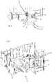
- Fig. 1 shows a schematic representation of a device 1 for reshaping plastic preforms into plastic containers.
- the plastic preforms 10 are fed to the individual reshaping stations 8 and expanded into plastic containers 20. After this expansion, the plastic containers are removed from the device again.
- a feed star can be provided, which feeds the plastic preforms to the device 1 and to a discharge device, in particular also a transport star, which discharges the finished containers from the device.
- the device 1 has a station carrier 12 on which a multiplicity of forming stations 8 are arranged. This station carrier can for example, as in Fig.
- blow molding 1 shown be a blowing wheel which is rotatable with respect to an axis of rotation D (which here runs perpendicular to the plane of the figure and thus vertically).
- Each individual forming station has a blow molding device 14.
- This blow molding device 14 is composed of two side parts and a bottom part. These blow molding devices can according to of the invention are replaced.
- the blow molding devices 14 are arranged on blow mold carriers 16 and can be removed from them or arranged on them.
- Reference numeral 40 denotes a changing device which is used to remove the blow molding devices from their blow mold carriers or to arrange the blow molding devices on the blow mold carriers.
- the reference numeral 6 denotes a base carrier on which the station carrier 12 is rotatably mounted.
- the changing device 40 is also arranged on or next to the base carrier 6.
- the changing device 40 can thus be integrated into the device.
- the reference numeral 18 denotes a housing which at least partially surrounds the station carrier 12, which, however, preferably, as shown below, can also enclose or house the changing device 40.
- the reference symbol W denotes a change position.
- the blow molding devices are preferably exchanged at a specific exchange position. This means that the forming stations can be successively moved into this change position W by rotating the carrier 12, and the old blow molding devices can then be removed from this change position and, preferably, new blow molding devices can also be supplied.
- the reference character R denotes a radial direction. In this radial direction, the changing device or a gripping device of the changing device is preferably fed to the forming stations or the blow molding devices in order to change them.
- FIG. 2 shows a perspective illustration of a device 1, only one forming device or forming station 8 being shown here.
- the station carrier on which this is arranged is also not shown here.
- the base carrier 6 on which the changing device 40 is arranged can also be seen again.
- This changing device 40 here has a first pivotable arm 56 and a second pivotable arm 54. These two arms are pivotably connected to one another via a joint and drive connection.
- Reference numeral 52 denotes a gripping device which is used to grip and transport the blow molding devices.
- This gripping device is in turn arranged pivotably on the second arm 54 and preferably also rotatable. So is Overall, the gripping device can be pivoted about at least three, preferably about at least four axes in space.
- Reference numeral 46 denotes schematically a detection device which detects forces acting on the changing device 40 or the gripping device 52 in order to be able to switch off in an emergency.
- the device advantageously has a plurality of such detection devices, with each individual drive device which brings about a movement of the changing device 40 or the gripping device 52 being assigned.
- These detection devices can, for example, be force measuring devices which determine actual forces, torques and the like. However, it would also be possible for the forces to be determined from parameters of the respective drive, for example from currents or the like.
- the reference character B identifies a user who operates the system. During operation of the changing device, the latter can advantageously not move in areas which can be reached by the changing device 40.
- Reference number 22 denotes a control device for controlling the changing device.
- Reference numeral 42 denotes a control device for controlling the shaping device itself.
- these two control devices can interact with one another, in particular for alternating operation for changing the blow molding devices. It is possible here for the changing device 40 to move into a rest position in normal working operation of the device, in which the changing device takes up as little space as possible.
- Fig. 3 shows a top view of the in Fig. 2 shown device. It can be seen here that the changing device 40 is also integrated into the housing 18. The in Fig. 3 In the state shown, the arm 56 is just pivoted out so that the gripping device 52 can just grip a blow molding device.
- a magazine device 70 which has a plurality of receiving points 72 for receiving the blow molding devices. These blow molding devices can each be moved into the receiving points or holes 72.
- Fig. 4 shows a further representation of the device according to the invention. It can be seen that a wall 32 is provided here, which separates the user B from the changing device 40, so that he cannot be injured.
- further movable wall parts 34 can also be provided so that on the one hand the machine is more easily accessible for maintenance purposes, or on the other hand further changing devices can also be provided, as also in FIG Fig. 1 shown.
- FIG. 5 The illustration shown is similar to that in Fig. 3 shown, but here the changing device 40 is in a different operating position.
- This can, for example, be a work operation in which the device reshapes plastic preforms into plastic containers. It can be seen that a recess 18a can be arranged in the housing 18, which recess also serves to completely accommodate the changing device 40.
- the in Fig. 5 The state shown, the individual arms of the changing device 40 can be folded in such that the changing device 40 only takes up a small amount of space.
- Fig. 6 shows a representation of a forming station 8.
- the blow mold carrier 16 can be seen here, which can have two blow mold carrier parts 16a, 16b that can be pivoted apart in order to open and close the blow molding device 14.
- the two blow mold support parts 16a, 16b can also be pivoted apart for alternating operation in order to be able to remove the blow molding device 14.
- the reference numeral 82 designates in its entirety a locking device which, during operation, locks the two blow mold carrier parts 16a and 16b with one another so that they do not pivot apart even when the pressures are greater.
- the reference numeral 66 relates to a projection which is arranged on each of the two side parts of the blow molding device 14. This projection is made so stable that the entire blow molding device 14 can be carried on this projection. This projection 66 can be grasped from behind by the gripping device or a component of the gripping device, so that the gripping device 52 carries the blow molding device via this projection can. By holding the respective side parts of the blow molding device on the projections 66, the blow molding device can also be held together in its entirety.
- Fig. 7 indicates a blow mold carrier shell.
- This blow mold carrier shell 15 can be arranged on the blow mold carrier 16 and in turn itself accommodate the blow molding device or parts of the blow molding device.
- supply and discharge elements 15a can be provided in order to supply media, such as temperature control media, to the blow mold shell 15.
- Fig. 8 shows a further illustration of the changing device 40.
- the first arm 56 is shown, which is pivotable with respect to a first axis A1.
- this arm 56 is also rotatable with respect to a second axis A2.
- a second arm 54 is arranged on this first arm 56 and the arm 54 is pivotable with respect to the first arm 56 with respect to an axis A3.
- the two axes A1 and A3 are parallel to each other. However, these axes can also be arranged obliquely or skewed to one another.
- the second arm 54 is also rotatable with respect to a fourth axis A4.
- a gripping device 52 is provided on the second arm 54, which is used to grip the blow molding device.
- This gripping element is pivotable relative to the arm 54 with respect to an axis A5.
- This axis A5 can be perpendicular to the axis A3 and / or also perpendicular to the axis A4.
- the gripping device is arranged on the arm 54 via a carrier 58. The gripping device itself can in turn be rotatable with respect to this carrier 58 with respect to an axis A6.
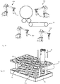
- the blow molding devices 14 can be removed from the individual forming station and placed on a carrier 74, which is shown here as a euro pallet. However, it would also be possible to introduce the blow molding devices 14 directly into openings provided in a magazine.
- a distance between the magazine device or the pallet 74 and the changing device 40 can be between 1 meter and 2 meters.
- a corresponding radius of action of the changing device can also be in a range of 1.5 meters.
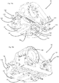
- Fig. 9 shows a detailed representation of the changing device 40 or its gripping device 52.
- This gripping device can have a guide element 62 which can be guided over a corresponding surface of the blow molding device.
- projections 64a, 64b can also be provided, which serve to center the changing device 40 or, more precisely, the gripping device with respect to the forming station.
- the reference numeral 63 relates to a recess which is arranged in the guide element 62 and which can engage behind the projections for changing the blow molding device.
- the guide element 62 thus also serves to carry the blow molding device 14.
- Fig. 10 shows a representation of the changing device with a blow molding device 14 arranged thereon.
- the gripping arm 52 engages here in two projections 66 arranged on the blow molding device 14 and compresses them so that the blow molding device is held together in this way.
- the gripping device 52 thus advantageously engages in elements above the blow molding device 14 in order to hold them.
- This type of engagement in the blow molding device is particularly suitable because the blow molding device, as in FIG Fig. 6 shown, protrudes beyond its carrier and in this way can also be gripped in a closed state of the blow mold carrier 16. It is thus possible that the changing device or the robot first grips the blow molding device 14 via its projections 66 and only then opens the blow mold carrier. In this way it can be ensured that the blow molding device is held securely at all times.
- FIG. 11 Figure 3 shows another illustration of the present invention.
- changing devices 40a-40d are provided here, with each of which elements of the device can be changed. It would be possible, for example, that two of the changing devices (40a, 40b) are provided to change blow molding devices 14, but that further changing devices are also provided that replace other elements, such as heating mandrels that are located in an oven 50 for heating the Plastic preforms are located (the changing device 40d).
- the shown changing device 40c can also be used, for example, to change holding elements such as transfer tongs, which transport the plastic preforms to the forming device 1 after they have been heated.
- Fig. 12 shows a receiving device such as a magazine for receiving the blow molding devices 14.
- This can contain a carrier plate 75 which has a multiplicity of openings 77.
- This plate 75 can be arranged on a base support 79 by means of supports 78, this base support 79 in turn having openings 79a or holes for receiving the blow molding devices.
- This magazine advantageously has the same dimensions as a so-called Euro pallet and thus preferably dimensions in an area of 1200 ⁇ 800 mm.
- the individual openings 79a are, as in FIG Fig. 12 shown, arranged in rows and offset from one another so that the largest possible number of blow molding devices can be introduced into the pallet.
- FIGs 13a - 13h illustrate a change process for a blow molding device, in which not the complete blow molding device is to be changed but only its side parts.
- a complete blow molding device 14 is arranged on a gripping device 52.
- the gripping device 52 removes the entire blow molding device, ie both the two side parts 14a and 14b and the bottom part 14c, which is mechanically coupled to the side parts 14a and 14b, from the blow molding machine.
- the entire blow molding device 14 is set down or arranged on a storage space (not shown) for the base part 14c.
- the gripping device 52 opens, as in FIG Figure 13d shown.
- two holding elements of the gripping device 52 which are explained in more detail below, can be pushed apart in order to also move the two side parts 14a and 14b apart.
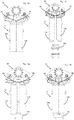
- FIGS 14a and 14b show an illustration of a gripping device which is also suitable and intended to move the two side parts apart in order to release the bottom part. It shows Figure 14a a view from above of the gripping device and Figure 14b a view from below. It can be seen that this gripping device 52 again has the two guide elements 62 in which the recesses 63 (for receiving the projections 66 arranged on the side parts) are arranged. However, while in the embodiment shown above this guide element 62 was formed in one piece, there are now two such Guide elements 62 are provided, which can be moved apart. For this purpose, these guide elements 62 (and thus also the recesses 63) are each arranged via a slide 104 on a carrier 102 and can be moved relative to this.
- Reference numeral 120 relates to a first drive device to get the in Figure 14a to move the left guide element shown and the reference numeral 130 relates to a drive device to move the in Figure 14a to move guide element 62 shown on the right.
- the reference numerals 122, 124, 132 and 134 identify communication connections for connecting a hydraulic or pneumatic means.
- retaining elements 142 are shown for securing the gripping device 52 to an arm.
- further connections 152, 154 are provided for hydraulic or pneumatic means in order to also bring about further degrees of freedom of movement, such as pivoting of the guide elements 62 in their entirety or also linear displacements.
- the guide elements 62 are set apart or removed from one another.
- the side parts, whose projections rest in the recesses 63, are also set apart, so that - as below Reference to the Figures 13a - 13h explained - now the bottom part can be removed from the side parts.
- the gripping device 52 thus enables a relative movement between the guide elements 63 or holding elements 62, which serve to hold or guide the side parts 14a, 14b of the blow molding device 14.
- the two guide elements 62 can each be moved along a rectilinear direction in order to remove the side parts of the blow molding device from one another or to bring them towards one another.
- the drives for carrying out this movement of the side parts apart and together are preferably pneumatic drives.
- Standard magazines can be used as magazines for storing the blow molding devices.
- Fig. 16 shows an embodiment of a device according to the invention.
- the shaping device 1 with the rotatable carrier 12 is shown again.
- a feed device 36 for feeding the plastic preforms, for example in the form of a transport star, and a discharge device 38 for discharging the manufactured plastic containers or plastic bottles are also provided.
- the reference symbol S1 relates to the first protected area within which the shaping device 1 is arranged.
- the reference symbol S2 identifies the second protected area within which the changing device 40 is arranged.
- the first protection area S1 is separated from the second protection area S2 by a separating element 160.
- This separating element 130 (for example in the form of a roller blind) can establish or interrupt a connection between the two protective areas S1 and S2. During work, it is conceivable that the first protection area S1 is closed and the second protection area S2 is open.
- Reference numeral 140 relates to a first magazine device in which a plurality of first side parts 14a and second side parts 14b of blow molding devices are arranged here. These side parts preferably have identification elements in order to be able to be clearly identified by the changing device.
- Reference number 145 denotes a second magazine device in which the base parts 14c of the blow molding devices 14 are arranged. These base parts 14c are also preferably clearly identifiable.
- Fig. 17 shows a representation of the changing device 40.
- two gripping devices 52, 53 (not shown in detail) are provided, with the two side parts 14a and 14b being arranged on one of the gripping device 52 as well as the bottom part 14c.
- the entire blow molding device 14 is thus arranged here on the gripping device.
- Reference numeral 182 denotes a holding device on which the two gripping devices are arranged.
- a carrier 184 is also provided, which is used to carry the two holding devices. This carrier can be rotated with respect to an axis of rotation Dr in order to selectively deliver the first gripping device 52 or the second gripping device 53 to the forming stations, for example.
- the reference symbols 92 and 93 each relate to identification devices which are used to identify blow molded parts.
- This can be, for example, RFID reading devices that are suitable for reading out RFID tags.
- These identification devices are arranged here on the gripping devices, but could also be arranged on the carrier 184.
- identification elements 150 are in turn arranged, which enable the individual blow molding devices to be clearly identified. This can be, for example, RFID tags or the like.
- the device preferably also has a memory device (not shown) in which the read-in data, for example data which characterize the blow molding devices, can be stored.
- blow molding devices It would be possible here for data that characterize the blow molding devices to be stored together with position data of the gripping device so that it can be determined at which location (e.g. within a magazine) a specific blow molding device is currently located.
- two gripping devices 52, 53 are also provided, but here one gripping device 52 for gripping the two side parts 14a and 14b of the blow molding device is used and the other gripping device 53 is used for gripping only one blow mold. As stated, however, each of the two gripping devices 52, 53 is optionally intended only for gripping the side parts, only for gripping a bottom part or for gripping an entire blow molding device having two side parts and a bottom part.
Landscapes
- Engineering & Computer Science (AREA)
- Mechanical Engineering (AREA)
- Manufacturing & Machinery (AREA)
- Robotics (AREA)
- Blow-Moulding Or Thermoforming Of Plastics Or The Like (AREA)
- Moulds For Moulding Plastics Or The Like (AREA)
Claims (13)
- Dispositif de formage de préformes en plastiques (10) en contenants en plastique (20) avec un dispositif de transport (2) qui transporte les préformes en plastiques (10) le long d'un trajet de transport prédéterminé, dans lequel le dispositif de transport (2) présente un support de poste mobile (12) sur lequel une pluralité de postes de formage (8) est disposée, dans lequel ces postes de formage (8) présentent chacun des dispositifs de moulage par soufflage (14) qui forment chacun des cavités à l'intérieur desquelles les préformes en plastique (10) peuvent être formées en contenants en plastique et ces dispositifs de moulage par soufflage (14) sont chacun agencés sur des supports de moule de soufflage (16), et le dispositif (1) présente un dispositif de changement (40) qui est adapté pour et destiné à retirer au moins les dispositifs de moulage par soufflage de leurs supports de moule de soufflage (16) et/ou à disposer des dispositifs de moulage par soufflage (14) sur les supports de moule de soufflage (16),
caractérisé en ce que
le dispositif de changement (40) présente un dispositif d'identification (92, 93) pour identifier les moules de soufflage (14) et/ou les parties de moules de soufflage (14a, 14b, 14c), dans lequel le dispositif d'identification (92, 93) a de préférence un dispositif de détection RFID. - Dispositif (1) selon la revendication 1,
caractérisé en ce que
au moins un dispositif de moulage par soufflage présente un élément RFID (150) qui peut être lu par un dispositif de détection RFID. - Dispositif (1) selon au moins l'une des revendications précédentes,
caractérisé en ce que
ce dispositif de changement (40) comporte au moins deux dispositifs de préhension (52, 53) pour saisir des dispositifs de moulage par soufflage (14), dans lequel au moins un de ces deux dispositifs de préhension (52, 53) est adapté à la fois pour saisir des dispositifs de moulage par soufflage (14) formés de plusieurs parties de moule de soufflage (14a, 14b, 14c) et pour saisir des parties individuelles de moule de soufflage (14a, 14b, 14c). - Dispositif (1) selon la revendication 3,
caractérisé en ce que
les deux dispositifs de préhension (52, 53) sont adaptés à la fois pour saisir des dispositifs de moulage par soufflage (14) formés de plusieurs parties de moule de soufflage (14a, 14b, 14c) et pour saisir des parties individuelles de moule de soufflage (14a, 14b, 14c). - Dispositif (1) selon au moins l'une des revendications précédentes,
caractérisé en ce que
les deux dispositifs de préhension (52, 53) sont disposés sur un support rotatif et/ou pivotant commun (184). - Dispositif (1) selon au moins l'une des revendications précédentes,
caractérisé en ce que
le dispositif de changement (40) présente un dispositif de détection de position pour détecter une position géométrique de moules de soufflage (14) et/ou de parties de moules de soufflage (14a, 14b, 14c). - Procédé de fonctionnement d'un dispositif de formage (1) pour former des préformes en plastique (10) en contenants en plastique (20), dans lequel, dans un mode de fonctionnement du dispositif (1), les préformes en plastique (10) sont transportées au moyen d'une pluralité de postes de formage (8) le long d'un trajet de transport prédéterminé et sont expansées en des contenants en plastique (20) par l'application d'un milieu fluide, dans lequel pour expanser les préformes en plastique (10) des dispositifs de moulage par soufflage (14) sont utilisés à l'intérieur desquels les préformes en plastique (10) sont expansées en contenants en plastique (20), dans lequel, en dans un mode de changement, au moins l'un des dispositifs de moulage par soufflage (14) est retiré du dispositif (1) et/ou l'un des dispositifs de moulage par soufflage (14) est disposé sur un support de moule de soufflage (16) du dispositif (1),
caractérisé en ce que
un dispositif de changement (40) est utilisé pour changer les dispositifs de moulage par soufflage (14) et au moins une partie (14a, 14b, 14c) d'au moins un dispositif de moulage par soufflage (14) à changer est identifiée au moyen d'au moins un dispositif d'identification (92, 93). - Procédé selon la revendication 7,
caractérisé en ce que
au moins un dispositif de préhension (52, 53) saisit au moins un dispositif de moulage par soufflage (14) dans une région supérieure par rapport à une direction longitudinale du dispositif de moulage par soufflage (14). - Procédé selon au moins l'une des revendications précédentes,
caractérisé en ce que
le dispositif de changement (40) saisit plusieurs parties de moule de soufflage (14a, 14b, 14c) au moyen d'au moins deux dispositifs de préhension (52, 53). - Procédé selon au moins l'une des revendications précédentes,
caractérisé en ce que
les dispositifs de moulage par soufflage (14) sont retirés des postes de formage (8), dans lequel un mouvement de retrait a lieu au moins temporairement perpendiculairement à une direction longitudinale des parties de moule de soufflage (14a, 14b). - Procédé selon au moins l'une des revendications précédentes,
caractérisé en ce que
un positionnement d'au moins un dispositif de moulage par soufflage (14) est détecté. - Procédé selon au moins l'une des revendications précédentes,
caractérisé en ce que
au moins un dispositif de préhension (52, 53) est équipé en alternance d'un dispositif de moulage par soufflage (14) à retirer du poste de formage (8) et d'un dispositif de moulage par soufflage (14) à disposer sur le poste de formage (8). - Procédé selon au moins l'une des revendications précédentes,
caractérisé en ce que
les parties de base (14c) du dispositif de moulage par soufflage (14) sont tournées par rapport à un axe qui est perpendiculaire à une direction longitudinale des contenants.
Priority Applications (1)
| Application Number | Priority Date | Filing Date | Title |
|---|---|---|---|
| EP20200364.6A EP3785881B1 (fr) | 2015-12-18 | 2016-12-19 | Changement de moules de soufflage dans les machines à mouler par soufflage |
Applications Claiming Priority (2)
| Application Number | Priority Date | Filing Date | Title |
|---|---|---|---|
| DE102015122324.4A DE102015122324A1 (de) | 2015-12-18 | 2015-12-18 | Wechsel von Blasformen bei Blasformmaschinen |
| PCT/EP2016/081801 WO2017103281A1 (fr) | 2015-12-18 | 2016-12-19 | Changement de moules de soufflage sur des machines de moulage par soufflage |
Related Child Applications (2)
| Application Number | Title | Priority Date | Filing Date |
|---|---|---|---|
| EP20200364.6A Division EP3785881B1 (fr) | 2015-12-18 | 2016-12-19 | Changement de moules de soufflage dans les machines à mouler par soufflage |
| EP20200364.6A Division-Into EP3785881B1 (fr) | 2015-12-18 | 2016-12-19 | Changement de moules de soufflage dans les machines à mouler par soufflage |
Publications (2)
| Publication Number | Publication Date |
|---|---|
| EP3294522A1 EP3294522A1 (fr) | 2018-03-21 |
| EP3294522B1 true EP3294522B1 (fr) | 2021-01-20 |
Family
ID=57570570
Family Applications (2)
| Application Number | Title | Priority Date | Filing Date |
|---|---|---|---|
| EP16813242.1A Active EP3294522B1 (fr) | 2015-12-18 | 2016-12-19 | Changement de moules de soufflage sur des machines de moulage par soufflage |
| EP20200364.6A Active EP3785881B1 (fr) | 2015-12-18 | 2016-12-19 | Changement de moules de soufflage dans les machines à mouler par soufflage |
Family Applications After (1)
| Application Number | Title | Priority Date | Filing Date |
|---|---|---|---|
| EP20200364.6A Active EP3785881B1 (fr) | 2015-12-18 | 2016-12-19 | Changement de moules de soufflage dans les machines à mouler par soufflage |
Country Status (5)
| Country | Link |
|---|---|
| US (1) | US20190009449A1 (fr) |
| EP (2) | EP3294522B1 (fr) |
| CN (1) | CN108025481B (fr) |
| DE (1) | DE102015122324A1 (fr) |
| WO (1) | WO2017103281A1 (fr) |
Cited By (1)
| Publication number | Priority date | Publication date | Assignee | Title |
|---|---|---|---|---|
| DE102024119490A1 (de) * | 2024-07-09 | 2026-01-15 | Khs Gmbh | Verfahren zum automatisierten Wechsel von Einrichtungen einer Umformstation und Umformvorrichtung mit einer Einrichtung für einen solchen automatisierten Wechsel |
Families Citing this family (9)
| Publication number | Priority date | Publication date | Assignee | Title |
|---|---|---|---|---|
| DE102017110272A1 (de) | 2017-05-11 | 2018-11-15 | Krones Ag | Verfahren zum Sterilisieren einer Blasformmaschine und Blasformmaschine |
| DE102017110270A1 (de) * | 2017-05-11 | 2018-11-15 | Krones Ag | Verfahren zum Sterilisieren einer Blasformmaschine und Blasformmaschine |
| DE102017129576A1 (de) * | 2017-12-12 | 2019-06-13 | Krones Ag | Vorrichtung und Verfahren zum Umformen von Kunststoffvorformlingen zu Kunststoffbehältnissen mit Bodenformtemperierung |
| DE102017120774A1 (de) | 2017-09-08 | 2019-03-14 | Krones Ag | Vorrichtung und Verfahren zum Umformen von Kunststoffvorformlingen zu Kunststoffbehältnissen mit Wechselroboter |
| DE102022121447A1 (de) * | 2022-08-24 | 2024-02-29 | Krones Aktiengesellschaft | Aseptische Blasform mit rückseitigen Abgaskanälen und Verfahren zum Formen von Behältnissen unter aseptischen Bedingungen |
| DE102023117198B4 (de) * | 2023-06-29 | 2026-03-05 | Khs Gmbh | Verfahren zum Betrieb einer Behälterbehandlungsanlage |
| DE102023119789A1 (de) | 2023-07-26 | 2025-01-30 | Khs Gmbh | Formatteil für eine Behälterfertigungsanlage sowie Behälterfertigungsanlage |
| DE102023134531A1 (de) * | 2023-12-11 | 2025-06-12 | Khs Gmbh | Vorrichtung und System zum Halten eines Formwerkzeugsegments, Handhabungsvorrichtung für ein Formwerkzeugsegment und Verfahren zum Wechseln eines Formwerkzeugsegments |
| DE102024127620A1 (de) | 2024-09-24 | 2026-03-26 | Khs Gmbh | Magazin, Wechselvorrichtung und Bereitstellungssystem für Formatteile, Umformvorrichtung mit Magazin und Verfahren zur Bereitstellung von Formatteile |
Citations (12)
| Publication number | Priority date | Publication date | Assignee | Title |
|---|---|---|---|---|
| DE102004043060A1 (de) | 2003-09-10 | 2005-04-07 | Engel Austria Gmbh | Spritzgießmaschine |
| EP2206565A1 (fr) | 2009-01-13 | 2010-07-14 | Krones AG | Dispositif et procédé destinés à la séparation de pré-pièces brutes |
| DE102009015522A1 (de) | 2009-04-02 | 2010-10-07 | Krones Ag | Vorrichtung zum Umformen von Kunststoffvorformlingen zu Kunststoffbehältnissen mit Formaterkennung |
| DE102009040977A1 (de) * | 2009-09-11 | 2011-03-17 | Krones Ag | Behältnisbehandlungsanlage und ein Behältnisbehandlungsverfahren zum Behandeln von mit einem Produkt befüllbaren Behältnissen |
| EP2511205A2 (fr) | 2011-04-13 | 2012-10-17 | Krones AG | Machine de traitement de récipient et procédé de traitement de récipient |
| DE102011050724A1 (de) | 2011-05-30 | 2012-12-06 | Krones Aktiengesellschaft | Simultanes Umrüsten von Verarbeitungsvorrichtungen |
| DE102011056627A1 (de) | 2011-12-19 | 2013-06-20 | Krones Aktiengesellschaft | Verfahren zum Betreiben einer Vorrichtung zum Umformen von Kunststoffvorformlingen zu Kunststoffbehältnissen und Vorrichtung zum Umformen von Kunststoffvorformlingen zu Kunststoffbehältnissen |
| DE102013109910A1 (de) | 2013-09-10 | 2015-03-12 | Harting Applied Technologies Gmbh | Vorrichtung zum Wechsel von Spritzgussformen |
| DE102013113077A1 (de) | 2013-11-26 | 2015-05-28 | Krones Ag | Blasformmaschine mit Blasformwechselroboter mit zusätzlicher Behandlungsfunktion |
| DE102013113076A1 (de) | 2013-11-26 | 2015-05-28 | Krones Ag | Blasformmaschine mit Wechselroboter und Verfahren zu deren Betrieb |
| EP2878423A1 (fr) * | 2013-11-26 | 2015-06-03 | Krones AG | Machine de formage par soufflage équipée de robots de remplacement et d'un dispositif de préhension, et son procédé de fonctionnement |
| DE102014103159A1 (de) | 2014-03-10 | 2015-09-24 | Krones Ag | Vorrichtung und Verfahren zum Umformen von Kunststoffvorformlingen zu Kunststoffbehältnissen mit automatischer Wechseleinrichtung für Garniturenteile |
Family Cites Families (8)
| Publication number | Priority date | Publication date | Assignee | Title |
|---|---|---|---|---|
| US5044922A (en) * | 1989-10-02 | 1991-09-03 | Owens-Illinois Plastic Products Inc. | Apparatus for applying labels in the molds of a plastic blow molding machine |
| DE29920715U1 (de) | 1999-11-25 | 2000-02-24 | Leuze Lumiflex GmbH & Co., 80993 München | Lichtschrankenanordnung zur Überwachung eines Gefahrenbereiches einer Maschine |
| FR2804059B1 (fr) * | 2000-01-20 | 2002-08-30 | Sidel Sa | Machine de soufflage de recipients comportant des moyens d'orientation des preformes dans le moule de soufflage |
| FR2954207B1 (fr) * | 2009-12-21 | 2013-09-27 | Sidel Participations | Machine pour la fabrication de recipients comportant un systeme d'assistance au changement de moule |
| DE102011054890A1 (de) * | 2011-10-28 | 2013-05-02 | Krones Aktiengesellschaft | Behälterbehandlungsanlage und Handhabungsvorrichtung |
| ITVR20130070A1 (it) * | 2013-03-22 | 2014-09-23 | Sacmi Imola Sc | Apparecchiatura per la realizzazione di contenitori in plastica |
| DE202013005658U1 (de) * | 2013-06-22 | 2014-06-23 | Krones Ag | Zapfanlage und Behälter |
| DE102014107512B4 (de) * | 2014-05-28 | 2016-02-25 | Krones Ag | Blasformeinrichtung mit vorspannbarer Befestigung für Blasformen |
-
2015
- 2015-12-18 DE DE102015122324.4A patent/DE102015122324A1/de active Pending
-
2016
- 2016-12-19 CN CN201680048176.1A patent/CN108025481B/zh active Active
- 2016-12-19 US US15/753,802 patent/US20190009449A1/en not_active Abandoned
- 2016-12-19 EP EP16813242.1A patent/EP3294522B1/fr active Active
- 2016-12-19 EP EP20200364.6A patent/EP3785881B1/fr active Active
- 2016-12-19 WO PCT/EP2016/081801 patent/WO2017103281A1/fr not_active Ceased
Patent Citations (12)
| Publication number | Priority date | Publication date | Assignee | Title |
|---|---|---|---|---|
| DE102004043060A1 (de) | 2003-09-10 | 2005-04-07 | Engel Austria Gmbh | Spritzgießmaschine |
| EP2206565A1 (fr) | 2009-01-13 | 2010-07-14 | Krones AG | Dispositif et procédé destinés à la séparation de pré-pièces brutes |
| DE102009015522A1 (de) | 2009-04-02 | 2010-10-07 | Krones Ag | Vorrichtung zum Umformen von Kunststoffvorformlingen zu Kunststoffbehältnissen mit Formaterkennung |
| DE102009040977A1 (de) * | 2009-09-11 | 2011-03-17 | Krones Ag | Behältnisbehandlungsanlage und ein Behältnisbehandlungsverfahren zum Behandeln von mit einem Produkt befüllbaren Behältnissen |
| EP2511205A2 (fr) | 2011-04-13 | 2012-10-17 | Krones AG | Machine de traitement de récipient et procédé de traitement de récipient |
| DE102011050724A1 (de) | 2011-05-30 | 2012-12-06 | Krones Aktiengesellschaft | Simultanes Umrüsten von Verarbeitungsvorrichtungen |
| DE102011056627A1 (de) | 2011-12-19 | 2013-06-20 | Krones Aktiengesellschaft | Verfahren zum Betreiben einer Vorrichtung zum Umformen von Kunststoffvorformlingen zu Kunststoffbehältnissen und Vorrichtung zum Umformen von Kunststoffvorformlingen zu Kunststoffbehältnissen |
| DE102013109910A1 (de) | 2013-09-10 | 2015-03-12 | Harting Applied Technologies Gmbh | Vorrichtung zum Wechsel von Spritzgussformen |
| DE102013113077A1 (de) | 2013-11-26 | 2015-05-28 | Krones Ag | Blasformmaschine mit Blasformwechselroboter mit zusätzlicher Behandlungsfunktion |
| DE102013113076A1 (de) | 2013-11-26 | 2015-05-28 | Krones Ag | Blasformmaschine mit Wechselroboter und Verfahren zu deren Betrieb |
| EP2878423A1 (fr) * | 2013-11-26 | 2015-06-03 | Krones AG | Machine de formage par soufflage équipée de robots de remplacement et d'un dispositif de préhension, et son procédé de fonctionnement |
| DE102014103159A1 (de) | 2014-03-10 | 2015-09-24 | Krones Ag | Vorrichtung und Verfahren zum Umformen von Kunststoffvorformlingen zu Kunststoffbehältnissen mit automatischer Wechseleinrichtung für Garniturenteile |
Non-Patent Citations (1)
| Title |
|---|
| WOLFSTEINER MANFRED: "Einfluss der Robotertechnik auf Beschäftigung und Tätigkeit", MITTEILUNGEN AUS DER ARBEITSMARKT- UND BERUFSFORSCHUNG, no. 2, 1 January 1983 (1983-01-01), pages 167 - 176, XP093029617 |
Cited By (1)
| Publication number | Priority date | Publication date | Assignee | Title |
|---|---|---|---|---|
| DE102024119490A1 (de) * | 2024-07-09 | 2026-01-15 | Khs Gmbh | Verfahren zum automatisierten Wechsel von Einrichtungen einer Umformstation und Umformvorrichtung mit einer Einrichtung für einen solchen automatisierten Wechsel |
Also Published As
| Publication number | Publication date |
|---|---|
| US20190009449A1 (en) | 2019-01-10 |
| CN108025481B (zh) | 2020-10-27 |
| EP3785881A1 (fr) | 2021-03-03 |
| CN108025481A (zh) | 2018-05-11 |
| DE102015122324A1 (de) | 2017-06-22 |
| WO2017103281A1 (fr) | 2017-06-22 |
| EP3785881B1 (fr) | 2022-09-07 |
| EP3294522A1 (fr) | 2018-03-21 |
Similar Documents
| Publication | Publication Date | Title |
|---|---|---|
| EP3294522B1 (fr) | Changement de moules de soufflage sur des machines de moulage par soufflage | |
| EP2878423B1 (fr) | Machine de formage par soufflage équipée de robots de remplacement et d'un dispositif de préhension, et son procédé de fonctionnement | |
| EP2878425B1 (fr) | Machine de formage par soufflage équipée de robots de remplacement et son procédé de fonctionnement | |
| EP2878424B1 (fr) | Machine de formage par soufflage équipée de robots de remplacement de formage par soufflage avec fonction de manutention supplémentaire | |
| EP2918391B1 (fr) | Dispositif et procédé de transformation d'ébauches en matière synthétique en récipients en plastique à l'aide de dispositif de changement automatique pour des parties de garnitures | |
| EP3294523B1 (fr) | Remplacement de moules de soufflage sur des machines de moulage par soufflage | |
| DE202012013536U1 (de) | System zur Unterstützung beim Formenwechsel der Blasstation einer Behälterproduktionsmaschine | |
| EP4344851B1 (fr) | Installation de fabrication de récipients en plastique avec robot interchangeable insérable universel et procédé associé | |
| EP3678827A1 (fr) | Dispositif et procédé de transformation de préformes en matière plastique en récipients en matière plastique au moyen d'un robot de changement | |
| DE19933847A1 (de) | Verfahren und Vorrichtung zur Blasformung von Behältern | |
| EP3619018A1 (fr) | Procédé servant à faire fonctionner un dispositif servant à façonner des préformes en matière plastique en des récipients en matière plastique, et dispositif |
Legal Events
| Date | Code | Title | Description |
|---|---|---|---|
| STAA | Information on the status of an ep patent application or granted ep patent |
Free format text: STATUS: UNKNOWN |
|
| STAA | Information on the status of an ep patent application or granted ep patent |
Free format text: STATUS: THE INTERNATIONAL PUBLICATION HAS BEEN MADE |
|
| PUAI | Public reference made under article 153(3) epc to a published international application that has entered the european phase |
Free format text: ORIGINAL CODE: 0009012 |
|
| STAA | Information on the status of an ep patent application or granted ep patent |
Free format text: STATUS: REQUEST FOR EXAMINATION WAS MADE |
|
| 17P | Request for examination filed |
Effective date: 20171214 |
|
| AK | Designated contracting states |
Kind code of ref document: A1 Designated state(s): AL AT BE BG CH CY CZ DE DK EE ES FI FR GB GR HR HU IE IS IT LI LT LU LV MC MK MT NL NO PL PT RO RS SE SI SK SM TR |
|
| AX | Request for extension of the european patent |
Extension state: BA ME |
|
| DAV | Request for validation of the european patent (deleted) | ||
| DAX | Request for extension of the european patent (deleted) | ||
| GRAP | Despatch of communication of intention to grant a patent |
Free format text: ORIGINAL CODE: EPIDOSNIGR1 |
|
| STAA | Information on the status of an ep patent application or granted ep patent |
Free format text: STATUS: GRANT OF PATENT IS INTENDED |
|
| INTG | Intention to grant announced |
Effective date: 20200715 |
|
| GRAJ | Information related to disapproval of communication of intention to grant by the applicant or resumption of examination proceedings by the epo deleted |
Free format text: ORIGINAL CODE: EPIDOSDIGR1 |
|
| STAA | Information on the status of an ep patent application or granted ep patent |
Free format text: STATUS: REQUEST FOR EXAMINATION WAS MADE |
|
| GRAS | Grant fee paid |
Free format text: ORIGINAL CODE: EPIDOSNIGR3 |
|
| STAA | Information on the status of an ep patent application or granted ep patent |
Free format text: STATUS: GRANT OF PATENT IS INTENDED |
|
| GRAP | Despatch of communication of intention to grant a patent |
Free format text: ORIGINAL CODE: EPIDOSNIGR1 |
|
| INTC | Intention to grant announced (deleted) | ||
| GRAA | (expected) grant |
Free format text: ORIGINAL CODE: 0009210 |
|
| STAA | Information on the status of an ep patent application or granted ep patent |
Free format text: STATUS: THE PATENT HAS BEEN GRANTED |
|
| INTG | Intention to grant announced |
Effective date: 20201123 |
|
| AK | Designated contracting states |
Kind code of ref document: B1 Designated state(s): AL AT BE BG CH CY CZ DE DK EE ES FI FR GB GR HR HU IE IS IT LI LT LU LV MC MK MT NL NO PL PT RO RS SE SI SK SM TR |
|
| REG | Reference to a national code |
Ref country code: GB Ref legal event code: FG4D Free format text: NOT ENGLISH |
|
| REG | Reference to a national code |
Ref country code: CH Ref legal event code: EP |
|
| REG | Reference to a national code |
Ref country code: AT Ref legal event code: REF Ref document number: 1355999 Country of ref document: AT Kind code of ref document: T Effective date: 20210215 |
|
| REG | Reference to a national code |
Ref country code: IE Ref legal event code: FG4D Free format text: LANGUAGE OF EP DOCUMENT: GERMAN |
|
| REG | Reference to a national code |
Ref country code: DE Ref legal event code: R096 Ref document number: 502016012273 Country of ref document: DE |
|
| REG | Reference to a national code |
Ref country code: NL Ref legal event code: MP Effective date: 20210120 |
|
| REG | Reference to a national code |
Ref country code: LT Ref legal event code: MG9D |
|
| PG25 | Lapsed in a contracting state [announced via postgrant information from national office to epo] |
Ref country code: FI Free format text: LAPSE BECAUSE OF FAILURE TO SUBMIT A TRANSLATION OF THE DESCRIPTION OR TO PAY THE FEE WITHIN THE PRESCRIBED TIME-LIMIT Effective date: 20210120 Ref country code: HR Free format text: LAPSE BECAUSE OF FAILURE TO SUBMIT A TRANSLATION OF THE DESCRIPTION OR TO PAY THE FEE WITHIN THE PRESCRIBED TIME-LIMIT Effective date: 20210120 Ref country code: GR Free format text: LAPSE BECAUSE OF FAILURE TO SUBMIT A TRANSLATION OF THE DESCRIPTION OR TO PAY THE FEE WITHIN THE PRESCRIBED TIME-LIMIT Effective date: 20210421 Ref country code: PT Free format text: LAPSE BECAUSE OF FAILURE TO SUBMIT A TRANSLATION OF THE DESCRIPTION OR TO PAY THE FEE WITHIN THE PRESCRIBED TIME-LIMIT Effective date: 20210520 Ref country code: NO Free format text: LAPSE BECAUSE OF FAILURE TO SUBMIT A TRANSLATION OF THE DESCRIPTION OR TO PAY THE FEE WITHIN THE PRESCRIBED TIME-LIMIT Effective date: 20210420 Ref country code: LT Free format text: LAPSE BECAUSE OF FAILURE TO SUBMIT A TRANSLATION OF THE DESCRIPTION OR TO PAY THE FEE WITHIN THE PRESCRIBED TIME-LIMIT Effective date: 20210120 Ref country code: BG Free format text: LAPSE BECAUSE OF FAILURE TO SUBMIT A TRANSLATION OF THE DESCRIPTION OR TO PAY THE FEE WITHIN THE PRESCRIBED TIME-LIMIT Effective date: 20210420 |
|
| PG25 | Lapsed in a contracting state [announced via postgrant information from national office to epo] |
Ref country code: SE Free format text: LAPSE BECAUSE OF FAILURE TO SUBMIT A TRANSLATION OF THE DESCRIPTION OR TO PAY THE FEE WITHIN THE PRESCRIBED TIME-LIMIT Effective date: 20210120 Ref country code: RS Free format text: LAPSE BECAUSE OF FAILURE TO SUBMIT A TRANSLATION OF THE DESCRIPTION OR TO PAY THE FEE WITHIN THE PRESCRIBED TIME-LIMIT Effective date: 20210120 Ref country code: PL Free format text: LAPSE BECAUSE OF FAILURE TO SUBMIT A TRANSLATION OF THE DESCRIPTION OR TO PAY THE FEE WITHIN THE PRESCRIBED TIME-LIMIT Effective date: 20210120 Ref country code: LV Free format text: LAPSE BECAUSE OF FAILURE TO SUBMIT A TRANSLATION OF THE DESCRIPTION OR TO PAY THE FEE WITHIN THE PRESCRIBED TIME-LIMIT Effective date: 20210120 |
|
| PG25 | Lapsed in a contracting state [announced via postgrant information from national office to epo] |
Ref country code: IS Free format text: LAPSE BECAUSE OF FAILURE TO SUBMIT A TRANSLATION OF THE DESCRIPTION OR TO PAY THE FEE WITHIN THE PRESCRIBED TIME-LIMIT Effective date: 20210520 |
|
| REG | Reference to a national code |
Ref country code: DE Ref legal event code: R026 Ref document number: 502016012273 Country of ref document: DE |
|
| PLBI | Opposition filed |
Free format text: ORIGINAL CODE: 0009260 |
|
| PG25 | Lapsed in a contracting state [announced via postgrant information from national office to epo] |
Ref country code: CZ Free format text: LAPSE BECAUSE OF FAILURE TO SUBMIT A TRANSLATION OF THE DESCRIPTION OR TO PAY THE FEE WITHIN THE PRESCRIBED TIME-LIMIT Effective date: 20210120 Ref country code: EE Free format text: LAPSE BECAUSE OF FAILURE TO SUBMIT A TRANSLATION OF THE DESCRIPTION OR TO PAY THE FEE WITHIN THE PRESCRIBED TIME-LIMIT Effective date: 20210120 Ref country code: SM Free format text: LAPSE BECAUSE OF FAILURE TO SUBMIT A TRANSLATION OF THE DESCRIPTION OR TO PAY THE FEE WITHIN THE PRESCRIBED TIME-LIMIT Effective date: 20210120 |
|
| PLAX | Notice of opposition and request to file observation + time limit sent |
Free format text: ORIGINAL CODE: EPIDOSNOBS2 |
|
| 26 | Opposition filed |
Opponent name: KHS GMBH Effective date: 20211019 |
|
| PG25 | Lapsed in a contracting state [announced via postgrant information from national office to epo] |
Ref country code: DK Free format text: LAPSE BECAUSE OF FAILURE TO SUBMIT A TRANSLATION OF THE DESCRIPTION OR TO PAY THE FEE WITHIN THE PRESCRIBED TIME-LIMIT Effective date: 20210120 Ref country code: SK Free format text: LAPSE BECAUSE OF FAILURE TO SUBMIT A TRANSLATION OF THE DESCRIPTION OR TO PAY THE FEE WITHIN THE PRESCRIBED TIME-LIMIT Effective date: 20210120 Ref country code: RO Free format text: LAPSE BECAUSE OF FAILURE TO SUBMIT A TRANSLATION OF THE DESCRIPTION OR TO PAY THE FEE WITHIN THE PRESCRIBED TIME-LIMIT Effective date: 20210120 |
|
| PG25 | Lapsed in a contracting state [announced via postgrant information from national office to epo] |
Ref country code: AL Free format text: LAPSE BECAUSE OF FAILURE TO SUBMIT A TRANSLATION OF THE DESCRIPTION OR TO PAY THE FEE WITHIN THE PRESCRIBED TIME-LIMIT Effective date: 20210120 Ref country code: ES Free format text: LAPSE BECAUSE OF FAILURE TO SUBMIT A TRANSLATION OF THE DESCRIPTION OR TO PAY THE FEE WITHIN THE PRESCRIBED TIME-LIMIT Effective date: 20210120 |
|
| PG25 | Lapsed in a contracting state [announced via postgrant information from national office to epo] |
Ref country code: SI Free format text: LAPSE BECAUSE OF FAILURE TO SUBMIT A TRANSLATION OF THE DESCRIPTION OR TO PAY THE FEE WITHIN THE PRESCRIBED TIME-LIMIT Effective date: 20210120 |
|
| PLBB | Reply of patent proprietor to notice(s) of opposition received |
Free format text: ORIGINAL CODE: EPIDOSNOBS3 |
|
| PG25 | Lapsed in a contracting state [announced via postgrant information from national office to epo] |
Ref country code: IS Free format text: LAPSE BECAUSE OF FAILURE TO SUBMIT A TRANSLATION OF THE DESCRIPTION OR TO PAY THE FEE WITHIN THE PRESCRIBED TIME-LIMIT Effective date: 20210520 |
|
| PG25 | Lapsed in a contracting state [announced via postgrant information from national office to epo] |
Ref country code: MC Free format text: LAPSE BECAUSE OF FAILURE TO SUBMIT A TRANSLATION OF THE DESCRIPTION OR TO PAY THE FEE WITHIN THE PRESCRIBED TIME-LIMIT Effective date: 20210120 |
|
| REG | Reference to a national code |
Ref country code: CH Ref legal event code: PL |
|
| GBPC | Gb: european patent ceased through non-payment of renewal fee |
Effective date: 20211219 |
|
| REG | Reference to a national code |
Ref country code: BE Ref legal event code: MM Effective date: 20211231 |
|
| PG25 | Lapsed in a contracting state [announced via postgrant information from national office to epo] |
Ref country code: LU Free format text: LAPSE BECAUSE OF NON-PAYMENT OF DUE FEES Effective date: 20211219 Ref country code: IE Free format text: LAPSE BECAUSE OF NON-PAYMENT OF DUE FEES Effective date: 20211219 Ref country code: GB Free format text: LAPSE BECAUSE OF NON-PAYMENT OF DUE FEES Effective date: 20211219 |
|
| PG25 | Lapsed in a contracting state [announced via postgrant information from national office to epo] |
Ref country code: BE Free format text: LAPSE BECAUSE OF NON-PAYMENT OF DUE FEES Effective date: 20211231 |
|
| PG25 | Lapsed in a contracting state [announced via postgrant information from national office to epo] |
Ref country code: LI Free format text: LAPSE BECAUSE OF NON-PAYMENT OF DUE FEES Effective date: 20211231 Ref country code: CH Free format text: LAPSE BECAUSE OF NON-PAYMENT OF DUE FEES Effective date: 20211231 |
|
| REG | Reference to a national code |
Ref country code: AT Ref legal event code: MM01 Ref document number: 1355999 Country of ref document: AT Kind code of ref document: T Effective date: 20211219 |
|
| PG25 | Lapsed in a contracting state [announced via postgrant information from national office to epo] |
Ref country code: AT Free format text: LAPSE BECAUSE OF NON-PAYMENT OF DUE FEES Effective date: 20211219 |
|
| PG25 | Lapsed in a contracting state [announced via postgrant information from national office to epo] |
Ref country code: HU Free format text: LAPSE BECAUSE OF FAILURE TO SUBMIT A TRANSLATION OF THE DESCRIPTION OR TO PAY THE FEE WITHIN THE PRESCRIBED TIME-LIMIT; INVALID AB INITIO Effective date: 20161219 |
|
| P01 | Opt-out of the competence of the unified patent court (upc) registered |
Effective date: 20230523 |
|
| PG25 | Lapsed in a contracting state [announced via postgrant information from national office to epo] |
Ref country code: NL Free format text: LAPSE BECAUSE OF NON-PAYMENT OF DUE FEES Effective date: 20210120 Ref country code: CY Free format text: LAPSE BECAUSE OF FAILURE TO SUBMIT A TRANSLATION OF THE DESCRIPTION OR TO PAY THE FEE WITHIN THE PRESCRIBED TIME-LIMIT Effective date: 20210120 |
|
| APAH | Appeal reference modified |
Free format text: ORIGINAL CODE: EPIDOSCREFNO |
|
| APBM | Appeal reference recorded |
Free format text: ORIGINAL CODE: EPIDOSNREFNO |
|
| APBP | Date of receipt of notice of appeal recorded |
Free format text: ORIGINAL CODE: EPIDOSNNOA2O |
|
| APBQ | Date of receipt of statement of grounds of appeal recorded |
Free format text: ORIGINAL CODE: EPIDOSNNOA3O |
|
| PG25 | Lapsed in a contracting state [announced via postgrant information from national office to epo] |
Ref country code: MK Free format text: LAPSE BECAUSE OF FAILURE TO SUBMIT A TRANSLATION OF THE DESCRIPTION OR TO PAY THE FEE WITHIN THE PRESCRIBED TIME-LIMIT Effective date: 20210120 |
|
| PG25 | Lapsed in a contracting state [announced via postgrant information from national office to epo] |
Ref country code: MT Free format text: LAPSE BECAUSE OF FAILURE TO SUBMIT A TRANSLATION OF THE DESCRIPTION OR TO PAY THE FEE WITHIN THE PRESCRIBED TIME-LIMIT Effective date: 20210120 |
|
| APBU | Appeal procedure closed |
Free format text: ORIGINAL CODE: EPIDOSNNOA9O |
|
| PLAY | Examination report in opposition despatched + time limit |
Free format text: ORIGINAL CODE: EPIDOSNORE2 |
|
| PG25 | Lapsed in a contracting state [announced via postgrant information from national office to epo] |
Ref country code: TR Free format text: LAPSE BECAUSE OF FAILURE TO SUBMIT A TRANSLATION OF THE DESCRIPTION OR TO PAY THE FEE WITHIN THE PRESCRIBED TIME-LIMIT Effective date: 20210120 |
|
| PLBC | Reply to examination report in opposition received |
Free format text: ORIGINAL CODE: EPIDOSNORE3 |
|
| PGFP | Annual fee paid to national office [announced via postgrant information from national office to epo] |
Ref country code: DE Payment date: 20251104 Year of fee payment: 10 |
|
| PGFP | Annual fee paid to national office [announced via postgrant information from national office to epo] |
Ref country code: IT Payment date: 20251121 Year of fee payment: 10 |
|
| PGFP | Annual fee paid to national office [announced via postgrant information from national office to epo] |
Ref country code: FR Payment date: 20251110 Year of fee payment: 10 |
|
| PLAY | Examination report in opposition despatched + time limit |
Free format text: ORIGINAL CODE: EPIDOSNORE2 |