EP3294645B1 - Porteur de caisse de véhicule et procédé de chargement d'une caisse de véhicule sur un tel porteur - Google Patents
Porteur de caisse de véhicule et procédé de chargement d'une caisse de véhicule sur un tel porteur Download PDFInfo
- Publication number
- EP3294645B1 EP3294645B1 EP16724973.9A EP16724973A EP3294645B1 EP 3294645 B1 EP3294645 B1 EP 3294645B1 EP 16724973 A EP16724973 A EP 16724973A EP 3294645 B1 EP3294645 B1 EP 3294645B1
- Authority
- EP
- European Patent Office
- Prior art keywords
- carrier
- vehicle body
- extension member
- support
- operatively
- Prior art date
- Legal status (The legal status is an assumption and is not a legal conclusion. Google has not performed a legal analysis and makes no representation as to the accuracy of the status listed.)
- Active
Links
Images

Classifications
-
- B—PERFORMING OPERATIONS; TRANSPORTING
- B65—CONVEYING; PACKING; STORING; HANDLING THIN OR FILAMENTARY MATERIAL
- B65D—CONTAINERS FOR STORAGE OR TRANSPORT OF ARTICLES OR MATERIALS, e.g. BAGS, BARRELS, BOTTLES, BOXES, CANS, CARTONS, CRATES, DRUMS, JARS, TANKS, HOPPERS, FORWARDING CONTAINERS; ACCESSORIES, CLOSURES, OR FITTINGS THEREFOR; PACKAGING ELEMENTS; PACKAGES
- B65D85/00—Containers, packaging elements or packages, specially adapted for particular articles or materials
- B65D85/68—Containers, packaging elements or packages, specially adapted for particular articles or materials for machines, engines or vehicles in assembled or dismantled form
-
- B—PERFORMING OPERATIONS; TRANSPORTING
- B60—VEHICLES IN GENERAL
- B60P—VEHICLES ADAPTED FOR LOAD TRANSPORTATION OR TO TRANSPORT, TO CARRY, OR TO COMPRISE SPECIAL LOADS OR OBJECTS
- B60P3/00—Vehicles adapted to transport, to carry or to comprise special loads or objects
- B60P3/06—Vehicles adapted to transport, to carry or to comprise special loads or objects for carrying vehicles
- B60P3/08—Multilevel-deck construction carrying vehicles
-
- B—PERFORMING OPERATIONS; TRANSPORTING
- B65—CONVEYING; PACKING; STORING; HANDLING THIN OR FILAMENTARY MATERIAL
- B65D—CONTAINERS FOR STORAGE OR TRANSPORT OF ARTICLES OR MATERIALS, e.g. BAGS, BARRELS, BOTTLES, BOXES, CANS, CARTONS, CRATES, DRUMS, JARS, TANKS, HOPPERS, FORWARDING CONTAINERS; ACCESSORIES, CLOSURES, OR FITTINGS THEREFOR; PACKAGING ELEMENTS; PACKAGES
- B65D2585/00—Containers, packaging elements or packages specially adapted for particular articles or materials
- B65D2585/68—Containers, packaging elements or packages specially adapted for particular articles or materials for machines, engines, or vehicles in assembled or dismantled form
- B65D2585/6802—Containers, packaging elements or packages specially adapted for particular articles or materials for machines, engines, or vehicles in assembled or dismantled form specific machines, engines or vehicles
- B65D2585/6875—Containers, packaging elements or packages specially adapted for particular articles or materials for machines, engines, or vehicles in assembled or dismantled form specific machines, engines or vehicles engines, motors, machines and vehicle parts
- B65D2585/6882—Containers, packaging elements or packages specially adapted for particular articles or materials for machines, engines, or vehicles in assembled or dismantled form specific machines, engines or vehicles engines, motors, machines and vehicle parts vehicle parts
- B65D2585/6887—Containers, packaging elements or packages specially adapted for particular articles or materials for machines, engines, or vehicles in assembled or dismantled form specific machines, engines or vehicles engines, motors, machines and vehicle parts vehicle parts body parts, e.g. doors, body panels
Definitions
- This invention relates to a vehicle body carrier. More particularly, but not exclusively, this invention relates to a vehicle body carrier for transporting vehicle bodies and/or loading vehicle bodies into intermodal containers. This invention also relates to a method of loading a vehicle body onto a vehicle body carrier.
- a widely used method of loading intermodal containers utilises a vehicle carrier that permits a first vehicle to be loaded onto the carrier in a generally horizontal orientation, and a second vehicle to also be loaded onto the carrier, but wherein it is supported in an inclined orientation above one end of the first vehicle.
- a vehicle carrier usually includes a pair of spaced apart tracks onto which the first vehicle is driven, and a pair of spaced apart ramps onto which the second vehicle is driven.
- a two part carrier assembly for vehicle according to the preamble of claim 1 is shown in CN103786998 A .
- a vehicle body carrier according to claim 1. It comprises a carrier base having first engaging means for, in use, engaging part of a first vehicle body to secure it on the carrier base.
- the first vehicle body may be secured in an operatively horizontal position.
- the vehicle body carrier includes a support arrangement extending operatively above the carrier base and having second engaging means for, in use engaging part of a second vehicle body to secure it on the support arrangement.
- the second vehicle body may be secured in an operatively inclined position at least partially above the first vehicle body.
- the vehicle body carrier further includes a carrier extension member to which the support arrangement is attached and from which it protrudes in an operatively upwardly direction, the carrier extension member is pivotally connected to the carrier base wherein it is pivotally displaceable relative to the carrier base between a first, collapsed position, wherein it is located adjacent to, coplanar and in line with the carrier base, and a second, slanted position, wherein it extends at an acute angle to the carrier base.
- the support arrangement may be removably attached to the carrier extension member.
- the carrier extension member may include a pair of spaced apart arms which extend parallel to each other from a reminder of the carrier extension member and which arms are pivotally connected at respective free ends thereof to opposing sides of the carrier base to facilitate the pivot connection between the carrier extension member and carrier base.
- the carrier extension member may be pivotally connected to the carrier base at a position intermediate opposing ends of the carrier base.
- the support arrangement may include a first support including the second engaging means at an operatively upper end thereof, and a second support including the second engaging means at an operatively upper end thereof, the first support being higher than the second support.
- Each of the first and second supports may include a pair of spaced apart operatively upwardly extending support members and a crossbar extending between free ends of the support members, and to which crossbar the second engaging means is attached.
- the crossbar may be removably attached to the support members.
- the first and second engaging means may be at least one or more engaging elements which are shaped and adapted such to be complementary to at least one or more co-operating formations in or on the first and second vehicle bodies.
- the element may be in the form of at least one or any combination of a lug, stud, pin, hook, aperture, hole, slot, recess and the like and the formation may be in the form of at least one or any combination of an aperture, hole, slot, recess, lug, stud, pin, hook and the like.
- the respective parts of the first and second vehicle bodies may be undersides and/or chassis of the respective first and second vehicle bodies.
- the carrier extension member is supported in its second, slanted position by means of at least one or more support legs.
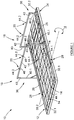
- a vehicle body carrier in accordance with the invention is generally indicated by reference numeral 10.
- the carrier 10 includes a carrier base 12 which has first engaging means 14 for, in use, engaging an underside of a first vehicle body 16 to secure it on the carrier base 12 in an operatively horizontal position, and a support arrangement 18 which extends operatively above the carrier base 12.
- the support arrangement 18 includes second engaging means 20 for, in use, engaging part of a second vehicle body 22 to secure it on the support arrangement 18 in an operatively inclined position.
- the vehicle body carrier 10 further includes a carrier extension member 24 which has a pair of spaced apart arms 26 which extend parallel to each other from a reminder of the extension member 24. At respective free ends 28 of the arms 26, the carrier extension member 24 is pivotally connected to opposing sides 30.1 and 30.2 of the carrier base 12 intermediate opposing ends 32.1 and 32.2 thereof.
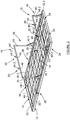
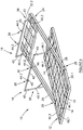
- the carrier extension member 24 is pivotally displaceable A about an operatively horizontal axis relative to the carrier base 12 between a first, collapsed position, wherein it is located adjacent to, in line and co-planar with the carrier base 12 (as shown in figures 1 , 2 and 5 ), and a second, slanted position, wherein it extends at an acute angle to the carrier base 12 in side view (as shown in figures 3 and 4 ).
- the carrier extension member 24 includes cavities 34 for receiving, in use, forks of a forklift (not shown) for lifting the carrier 10, loading it into an intermodal container (not shown) and/or manipulating its position in the container.
- the cavities 34 also extend into the carrier base 12.
- the support arrangement 18 is attached to and protrudes from the carrier extension member 24 in an operatively upwardly direction.
- the support arrangement 18 includes a first support 36 having the second engaging means 20 at an operatively upper end thereof, and a second support 38 including the second engaging means 20 at an operatively upper end thereof.
- the first support 36 which is spaced longitudinally along the carrier extension member 24 from the second support 38, is longer than the second support 38. Therefore, when the carrier extension member 24 is in its first, collapsed position, the first support 36 stands at a higher vertical distance B from the carrier base 12 than the second support 38.
- Each of the first and second supports 36 and 38 includes a pair of spaced apart operatively upwardly extending support members 40.1 or 40.2.
- the support members 40 are permanently attached to the carrier extension member 24, although in other embodiments of the invention the support members 40 could be removably attached to the carrier extension member 24.
- Support members 40.1, being part of the first support 36, are longer than support members 40.2, being part of the second support 38.
- Each of the first and second supports 36 and 38 further includes a crossbar 42 which extends between free ends of the respective support members 40.
- the second engaging means 20 is attached to the crossbars 42.
- the crossbars 42 are removably attached to the support members 40 by having sleeves 43 at their opposing free ends extending laterally therefrom, which sleeves 43 are able to locate and slide over the free ends of the support members 40.
- the crossbars 42 could be permanently attached to the relevant support members 40.
- Each of the first and second engaging means 14 and 20 includes a plurality of engaging elements which, according to this example embodiment, is in the form of operatively upwardly extending pins 44.1 and 44.2.
- the pins 44 are shaped and adapted such to be complementary to at least one or more co-operating formations (not shown) in the vehicle bodies 16 and 22.
- the co-operating formations are in the form of apertures which receives the pins 44 therein.
- the pins 44.1 of the first engaging means 14 protrude from the carrier base 12, and the pins 44.2 of the second engaging means 20 protrude from lugs 46 which are attached to the crossbars 42, as shown.
- the first vehicle body 16 is generally first loaded onto the carrier 10. This is performed by ensuring that the carrier extension member 24 is in its first, collapsed position. The first vehicle body 16 is then lowered, by whatever hoisting means, such as a crane, slings or forklift (not shown), in a substantially horizontal orientation onto the carrier base 12 so that the first engaging means 14 engages the underside of the first vehicle body 16 to secure it in position on the carrier base 12.
- hoisting means such as a crane, slings or forklift (not shown)
- the support arrangement 18 when loading the second vehicle body 22 onto the carrier 10, the support arrangement 18 is assembled by removably attaching the crossbars 42 between the respective support members 40.1 and 40.2 of each pair of support members.
- the carrier extension member 24 is then displaced from its first, collapsed position to its second, slanted position wherein the respective crossbars 42 of the first and second supports 36 and 38 are positioned at roughly equal operatively vertical distances B from the carrier base 12.
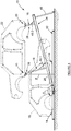
- the carrier extension member 24 is supported in its second, slanted position by positioning at least one, but preferably two support legs 48 underneath it, as shown.
- the second vehicle body 22 is then lowered, by whatever hoisting means, such as a crane or forklift (not shown), in a substantially horizontal orientation onto the support arrangement 18 so that the second engaging means 20 engages the underside of the second vehicle body 22 to secure it in position on the support arrangement 18.
- hoisting means such as a crane or forklift (not shown)
- the support legs 48 are removed from underneath the carrier extension member 24 and it is displaced from its second, slanted position to its first, collapsed position so that the second vehicle body 22 is supported on the support arrangement 18 in an inclined position.
- vehicle bodies 16 and 22 could be further secured to the carrier 10 by additional securing means (no shown) such as lashings, straps, fasteners, or the like.
- the vehicle body carrier 10 When fully loaded, the vehicle body carrier 10 is self supporting, meaning that the vehicle bodies 16 and 22 could be pre-staged or even stored on the carrier 10 while awaiting loading into an intermodal container, for example.
- the carrier 10 when loading the fully loaded carrier 10 into a container, the carrier 10 is picked up, typically by a forklift, and loaded either into a grounded container or one that is on a truck chassis (not shown). This means the loaded carrier 10 could be driven into the container by the forklift and placed in position in the container, or it can be placed at a door end of the container and slid further into the container. Further loaded carriers could thereafter be slid in behind the first one, wherein a plurality of loaded carriers is positioned end-to-end inside the loaded container.
- the unloading process is similar to the loading process discussed above. However, when loaded carriers are to be removed from a container located on a truck chassis, the carrier positioned closest to the door end of the container is removed first by a forklift. A rope or line (not shown) is then attached to the carrier being closest to the door end of the container and pulled to the door of the container from where the forklift can remove that carrier from the container. This process is repeated for the remaining carriers in the container.
- this invention provides a useful vehicle body carrier 10 that could be used for easily and conveniently transporting parts of vehicles such as semi-knocked-down vehicles or even assembled vehicles from one location to another during the vehicle manufacturing and/or assembly stages.
- the invention may incorporate further engaging means for engaging and securing the respective first and second vehicle bodies 16 and 22 to the vehicle body carrier 10, such as, for example, fasteners, straps, ropes and the like.
- the first and second engaging means 14 and 20 could be easily adapted to engage any other part of the vehicle bodies 16 and 22, such as the chassis (not shown).
- the engaging elements and co-operating formations could alternatively be in the form of any one or any combination of an aperture, hole, slot, recess, lug, stud, pin and hook.
- one or more brace members (not shown) could be provided between the first and second supports 36 and 38 to afford further reinforcement to the support arrangement 18.
Landscapes
- Engineering & Computer Science (AREA)
- Mechanical Engineering (AREA)
- Health & Medical Sciences (AREA)
- Public Health (AREA)
- Transportation (AREA)
- Fittings On The Vehicle Exterior For Carrying Loads, And Devices For Holding Or Mounting Articles (AREA)
- Auxiliary Methods And Devices For Loading And Unloading (AREA)
Claims (7)
- Support de carrosserie de véhicule (10), comprenant :- une base de support (12), comportant des premiers moyens d'engagement (14) destinés à s'engager, en cours d'utilisation, avec une partie d'une première carrosserie de véhicule (16) pour fixer celle-ci sur la base de support (12) dans une position fonctionnellement horizontale ;- un élément d'extension de support (24) ; dans lequel un agencement de support (18) est fixé à l'élément d'extension de support (24) et fait saillie de celui-ci dans une direction fonctionnellement vers le haut dans laquelle il s'étend fonctionnellement au-dessus de la base de support (12), l'agencement de support (18) comprenant des deuxièmes moyens d'engagement (20) destinés à s'engager, en cours d'utilisation, avec une partie d'une deuxième carrosserie de véhicule (22) afin de fixer celle-ci sur l'agencement de support (18) dans une position fonctionnellement inclinée au moins en partie au-dessus de la première carrosserie de véhicule (16), caractérisé en ce que l'élément d'extension de support (24) est relié de manière pivotante à la base de support (12) dans laquelle il peut être déplacé de manière pivotante par rapport à la base de support (12) entre une première position repliée, dans laquelle il est situé de manière adjacente à la base de support (12), en alignement et de manière coplanaire avec celle-ci, et une deuxième position inclinée dans laquelle il s'étend en formant un angle aigu avec la base de support (12).
- Support (10) selon la revendication 1, dans lequel l'élément d'extension de support (24) comprend des cavités (34) destinées à recevoir, en cours d'utilisation, des fourches d'un chariot élévateur à fourche destiné à soulever le support (10), le charger dans un conteneur intermodal et/ou manipuler sa position dans le conteneur, dans lequel les cavités s'étendent également à l'intérieur de la base de support (12).
- Support (10) selon la revendication 1 ou 2, dans lequel l'élément d'extension de support (24) comprend une paire de bras espacés (26) qui s'étendent parallèlement l'un à l'autre depuis le reste de l'élément d'extension de support (24), lesquels bras (26) sont reliés de manière pivotante, au niveau de leurs extrémités libres respectives (28), à des côtés opposés (30) de la base de support (12), entre ses extrémités opposées (32), afin de faciliter la liaison à pivotement entre l'élément d'extension de support (24) et la base de support (12).
- Support (10) selon l'une quelconque des revendications précédentes, dans lequel l'agencement de support (18) comprend un premier support (36) comportant les deuxièmes moyens d'engagement (20) au niveau de son extrémité fonctionnellement supérieure, et un deuxième support (38) qui est espacé longitudinalement du premier support (36) sur la longueur de l'élément d'extension (24) et comprend les deuxièmes moyens d'engagement (20) au niveau de son extrémité fonctionnellement supérieure, le premier support (36) étant plus élevé que le deuxième support (38).
- Support (10) selon la revendication 4, dans lequel chacun des premier (36) et deuxième (38) supports comprend une paire d'éléments de support espacés (40) s'étendant fonctionnellement vers le haut et une barre transversale (42) s'étendant entre des extrémités libres des éléments de support (40), avec la barre transversale (42) comprenant les deuxièmes moyens d'engagement (20) fixés à celui-ci.
- Support (10) selon l'une quelconque des revendications précédentes, dans lequel les premiers (14) et deuxièmes (20) moyens d'engagement comprennent au moins un élément d'engagement (44) qui est formé et adapté de manière à être complémentaire d'au moins une formation coopérante dans ou sur les première (16) et deuxième (22) carrosseries de véhicule.
- Procédé de chargement d'une carrosserie de véhicule sur un support de carrosserie de véhicule, le procédé comprenant les étapes suivantes :- fournir un support de carrosserie de véhicule (10) selon la revendication 1,- déplacer l'élément d'extension de support (24) de sa première position repliée vers sa deuxième position inclinée ;- supporter l'élément d'extension de support (24) dans sa deuxième position inclinée ;- abaisser la deuxième carrosserie de véhicule (22), dans une orientation sensiblement horizontale, sur l'agencement de support (18) de sorte qu'une partie de la deuxième carrosserie de véhicule (22) s'engage avec les deuxièmes moyens d'engagement (20) pour fixer celle-ci en position sur l'agencement de support (18) ; et- déplacer l'élément d'extension de support (24) de sa deuxième position inclinée vers sa première position repliée de sorte que la deuxième carrosserie du véhicule (22) soit supportée par l'agencement de support (18) dans une position fonctionnellement inclinée.
Applications Claiming Priority (2)
| Application Number | Priority Date | Filing Date | Title |
|---|---|---|---|
| ZA201503431 | 2015-05-15 | ||
| PCT/IB2016/052761 WO2016185338A1 (fr) | 2015-05-15 | 2016-05-13 | Porteur de caisse de véhicule et procédé de chargement d'un véhicule sur un tel porteur |
Publications (2)
| Publication Number | Publication Date |
|---|---|
| EP3294645A1 EP3294645A1 (fr) | 2018-03-21 |
| EP3294645B1 true EP3294645B1 (fr) | 2019-07-03 |
Family
ID=56080429
Family Applications (1)
| Application Number | Title | Priority Date | Filing Date |
|---|---|---|---|
| EP16724973.9A Active EP3294645B1 (fr) | 2015-05-15 | 2016-05-13 | Porteur de caisse de véhicule et procédé de chargement d'une caisse de véhicule sur un tel porteur |
Country Status (5)
| Country | Link |
|---|---|
| EP (1) | EP3294645B1 (fr) |
| CN (1) | CN107848697B (fr) |
| ES (1) | ES2745493T3 (fr) |
| WO (1) | WO2016185338A1 (fr) |
| ZA (1) | ZA201708456B (fr) |
Families Citing this family (1)
| Publication number | Priority date | Publication date | Assignee | Title |
|---|---|---|---|---|
| GB2594645B (en) * | 2018-07-09 | 2022-04-20 | Trans Rak International Ltd | Vehicle transportation systems |
Family Cites Families (6)
| Publication number | Priority date | Publication date | Assignee | Title |
|---|---|---|---|---|
| US5769591A (en) * | 1993-02-04 | 1998-06-23 | Kar-Tainer International, Inc. | Frame structure and method of packing vehicle bodies |
| JP4221325B2 (ja) * | 2004-03-31 | 2009-02-12 | 日本郵船株式会社 | 車輌積付け方法およびその装置 |
| CN201506574U (zh) * | 2009-08-27 | 2010-06-16 | 浙江金刚汽车有限公司 | 轿车包装可回收货架 |
| DE202010009806U1 (de) * | 2010-07-02 | 2010-10-14 | Holzindustrie Fürst zu Fürstenberg GmbH & Co. KG | Transportgestell für den Transport von Fahrzeugkarosserien |
| CN202429501U (zh) * | 2011-08-08 | 2012-09-12 | 佛罗伦集装箱服务(深圳)有限公司 | 车辆运输支架及车辆运输装置 |
| CN103786998B (zh) * | 2014-02-17 | 2015-10-07 | 裘褚兵 | 汽车运输装置 |
-
2016
- 2016-05-13 CN CN201680041022.XA patent/CN107848697B/zh active Active
- 2016-05-13 ES ES16724973T patent/ES2745493T3/es active Active
- 2016-05-13 WO PCT/IB2016/052761 patent/WO2016185338A1/fr not_active Ceased
- 2016-05-13 EP EP16724973.9A patent/EP3294645B1/fr active Active
-
2017
- 2017-12-13 ZA ZA2017/08456A patent/ZA201708456B/en unknown
Non-Patent Citations (1)
| Title |
|---|
| None * |
Also Published As
| Publication number | Publication date |
|---|---|
| CN107848697A (zh) | 2018-03-27 |
| ES2745493T3 (es) | 2020-03-02 |
| ZA201708456B (en) | 2019-12-18 |
| WO2016185338A1 (fr) | 2016-11-24 |
| CN107848697B (zh) | 2019-10-18 |
| EP3294645A1 (fr) | 2018-03-21 |
Similar Documents
| Publication | Publication Date | Title |
|---|---|---|
| CN103026060B (zh) | 用于操纵风力涡轮机塔架段的系统及方法 | |
| US11046371B2 (en) | System for conveying and stowing elongated material | |
| JP5990527B2 (ja) | 補助輸送ユニット及びその使用方法 | |
| CN106536359B (zh) | 输送辅助装置及其使用方法 | |
| US9260142B2 (en) | Shipping container transport system | |
| AU2016353534B2 (en) | Modular transportation and storage system | |
| US8272623B2 (en) | Container lifting device | |
| US8066460B2 (en) | Apparatus and method for cargo loading system | |
| US7810861B1 (en) | Hoisting device, transporting system, and methods | |
| EP3294645B1 (fr) | Porteur de caisse de véhicule et procédé de chargement d'une caisse de véhicule sur un tel porteur | |
| EP2818044A1 (fr) | Système et procédé pour manipuler des volailles vivantes | |
| US8419095B2 (en) | Pallet system and method for use thereof | |
| EP1946963A1 (fr) | Véhicule doté d'un espace de chargement | |
| JP2007320727A (ja) | コンテナ用ガントリークレーン、コンテナ輸送用パレット、コンテナ搬送車、および、コンテナ輸送方法 | |
| KR20130006534U (ko) | 지게차 포크 부착형 지그 | |
| CN110053892A (zh) | 运输架 | |
| WO2004071868A1 (fr) | Fourgon a bagages | |
| KR200426101Y1 (ko) | 유리박스 이송을 위한 기구 | |
| CN209010091U (zh) | 一种倾桶用的叉车防滑装置 | |
| KR200295648Y1 (ko) | 화물운반용 손수레 | |
| AU2007100972A4 (en) | Improvements to transportable lifting devices | |
| KR100615112B1 (ko) | 다중 자동차 운반시스템 | |
| US12473045B1 (en) | Trailer pallet | |
| FI126612B (fi) | Menetelmä vaihtolavojen kuljettamiseksi perävaunullisessa kuljetusajoneuvossa ja vaihtolavasarja | |
| JPH0142546Y2 (fr) |
Legal Events
| Date | Code | Title | Description |
|---|---|---|---|
| STAA | Information on the status of an ep patent application or granted ep patent |
Free format text: STATUS: THE INTERNATIONAL PUBLICATION HAS BEEN MADE |
|
| PUAI | Public reference made under article 153(3) epc to a published international application that has entered the european phase |
Free format text: ORIGINAL CODE: 0009012 |
|
| STAA | Information on the status of an ep patent application or granted ep patent |
Free format text: STATUS: REQUEST FOR EXAMINATION WAS MADE |
|
| 17P | Request for examination filed |
Effective date: 20171215 |
|
| AK | Designated contracting states |
Kind code of ref document: A1 Designated state(s): AL AT BE BG CH CY CZ DE DK EE ES FI FR GB GR HR HU IE IS IT LI LT LU LV MC MK MT NL NO PL PT RO RS SE SI SK SM TR |
|
| AX | Request for extension of the european patent |
Extension state: BA ME |
|
| DAV | Request for validation of the european patent (deleted) | ||
| DAX | Request for extension of the european patent (deleted) | ||
| RIC1 | Information provided on ipc code assigned before grant |
Ipc: B60P 3/08 20060101ALI20181203BHEP Ipc: B65D 85/68 20060101AFI20181203BHEP |
|
| GRAP | Despatch of communication of intention to grant a patent |
Free format text: ORIGINAL CODE: EPIDOSNIGR1 |
|
| STAA | Information on the status of an ep patent application or granted ep patent |
Free format text: STATUS: GRANT OF PATENT IS INTENDED |
|
| INTG | Intention to grant announced |
Effective date: 20190125 |
|
| GRAS | Grant fee paid |
Free format text: ORIGINAL CODE: EPIDOSNIGR3 |
|
| GRAA | (expected) grant |
Free format text: ORIGINAL CODE: 0009210 |
|
| STAA | Information on the status of an ep patent application or granted ep patent |
Free format text: STATUS: THE PATENT HAS BEEN GRANTED |
|
| AK | Designated contracting states |
Kind code of ref document: B1 Designated state(s): AL AT BE BG CH CY CZ DE DK EE ES FI FR GB GR HR HU IE IS IT LI LT LU LV MC MK MT NL NO PL PT RO RS SE SI SK SM TR |
|
| REG | Reference to a national code |
Ref country code: GB Ref legal event code: FG4D |
|
| REG | Reference to a national code |
Ref country code: CH Ref legal event code: EP Ref country code: AT Ref legal event code: REF Ref document number: 1150730 Country of ref document: AT Kind code of ref document: T Effective date: 20190715 |
|
| REG | Reference to a national code |
Ref country code: DE Ref legal event code: R096 Ref document number: 602016016327 Country of ref document: DE |
|
| REG | Reference to a national code |
Ref country code: IE Ref legal event code: FG4D |
|
| REG | Reference to a national code |
Ref country code: SK Ref legal event code: T3 Ref document number: E 31988 Country of ref document: SK |
|
| REG | Reference to a national code |
Ref country code: NL Ref legal event code: MP Effective date: 20190703 |
|
| REG | Reference to a national code |
Ref country code: LT Ref legal event code: MG4D |
|
| REG | Reference to a national code |
Ref country code: AT Ref legal event code: MK05 Ref document number: 1150730 Country of ref document: AT Kind code of ref document: T Effective date: 20190703 |
|
| PG25 | Lapsed in a contracting state [announced via postgrant information from national office to epo] |
Ref country code: FI Free format text: LAPSE BECAUSE OF FAILURE TO SUBMIT A TRANSLATION OF THE DESCRIPTION OR TO PAY THE FEE WITHIN THE PRESCRIBED TIME-LIMIT Effective date: 20190703 Ref country code: AT Free format text: LAPSE BECAUSE OF FAILURE TO SUBMIT A TRANSLATION OF THE DESCRIPTION OR TO PAY THE FEE WITHIN THE PRESCRIBED TIME-LIMIT Effective date: 20190703 Ref country code: NO Free format text: LAPSE BECAUSE OF FAILURE TO SUBMIT A TRANSLATION OF THE DESCRIPTION OR TO PAY THE FEE WITHIN THE PRESCRIBED TIME-LIMIT Effective date: 20191003 Ref country code: SE Free format text: LAPSE BECAUSE OF FAILURE TO SUBMIT A TRANSLATION OF THE DESCRIPTION OR TO PAY THE FEE WITHIN THE PRESCRIBED TIME-LIMIT Effective date: 20190703 Ref country code: PT Free format text: LAPSE BECAUSE OF FAILURE TO SUBMIT A TRANSLATION OF THE DESCRIPTION OR TO PAY THE FEE WITHIN THE PRESCRIBED TIME-LIMIT Effective date: 20191104 Ref country code: HR Free format text: LAPSE BECAUSE OF FAILURE TO SUBMIT A TRANSLATION OF THE DESCRIPTION OR TO PAY THE FEE WITHIN THE PRESCRIBED TIME-LIMIT Effective date: 20190703 Ref country code: NL Free format text: LAPSE BECAUSE OF FAILURE TO SUBMIT A TRANSLATION OF THE DESCRIPTION OR TO PAY THE FEE WITHIN THE PRESCRIBED TIME-LIMIT Effective date: 20190703 Ref country code: LT Free format text: LAPSE BECAUSE OF FAILURE TO SUBMIT A TRANSLATION OF THE DESCRIPTION OR TO PAY THE FEE WITHIN THE PRESCRIBED TIME-LIMIT Effective date: 20190703 |
|
| PG25 | Lapsed in a contracting state [announced via postgrant information from national office to epo] |
Ref country code: RS Free format text: LAPSE BECAUSE OF FAILURE TO SUBMIT A TRANSLATION OF THE DESCRIPTION OR TO PAY THE FEE WITHIN THE PRESCRIBED TIME-LIMIT Effective date: 20190703 Ref country code: LV Free format text: LAPSE BECAUSE OF FAILURE TO SUBMIT A TRANSLATION OF THE DESCRIPTION OR TO PAY THE FEE WITHIN THE PRESCRIBED TIME-LIMIT Effective date: 20190703 Ref country code: AL Free format text: LAPSE BECAUSE OF FAILURE TO SUBMIT A TRANSLATION OF THE DESCRIPTION OR TO PAY THE FEE WITHIN THE PRESCRIBED TIME-LIMIT Effective date: 20190703 Ref country code: GR Free format text: LAPSE BECAUSE OF FAILURE TO SUBMIT A TRANSLATION OF THE DESCRIPTION OR TO PAY THE FEE WITHIN THE PRESCRIBED TIME-LIMIT Effective date: 20191004 Ref country code: IS Free format text: LAPSE BECAUSE OF FAILURE TO SUBMIT A TRANSLATION OF THE DESCRIPTION OR TO PAY THE FEE WITHIN THE PRESCRIBED TIME-LIMIT Effective date: 20191103 |
|
| REG | Reference to a national code |
Ref country code: ES Ref legal event code: FG2A Ref document number: 2745493 Country of ref document: ES Kind code of ref document: T3 Effective date: 20200302 |
|
| PG25 | Lapsed in a contracting state [announced via postgrant information from national office to epo] |
Ref country code: TR Free format text: LAPSE BECAUSE OF FAILURE TO SUBMIT A TRANSLATION OF THE DESCRIPTION OR TO PAY THE FEE WITHIN THE PRESCRIBED TIME-LIMIT Effective date: 20190703 |
|
| PG25 | Lapsed in a contracting state [announced via postgrant information from national office to epo] |
Ref country code: EE Free format text: LAPSE BECAUSE OF FAILURE TO SUBMIT A TRANSLATION OF THE DESCRIPTION OR TO PAY THE FEE WITHIN THE PRESCRIBED TIME-LIMIT Effective date: 20190703 Ref country code: PL Free format text: LAPSE BECAUSE OF FAILURE TO SUBMIT A TRANSLATION OF THE DESCRIPTION OR TO PAY THE FEE WITHIN THE PRESCRIBED TIME-LIMIT Effective date: 20190703 Ref country code: DK Free format text: LAPSE BECAUSE OF FAILURE TO SUBMIT A TRANSLATION OF THE DESCRIPTION OR TO PAY THE FEE WITHIN THE PRESCRIBED TIME-LIMIT Effective date: 20190703 Ref country code: IT Free format text: LAPSE BECAUSE OF FAILURE TO SUBMIT A TRANSLATION OF THE DESCRIPTION OR TO PAY THE FEE WITHIN THE PRESCRIBED TIME-LIMIT Effective date: 20190703 Ref country code: RO Free format text: LAPSE BECAUSE OF FAILURE TO SUBMIT A TRANSLATION OF THE DESCRIPTION OR TO PAY THE FEE WITHIN THE PRESCRIBED TIME-LIMIT Effective date: 20190703 |
|
| PG25 | Lapsed in a contracting state [announced via postgrant information from national office to epo] |
Ref country code: IS Free format text: LAPSE BECAUSE OF FAILURE TO SUBMIT A TRANSLATION OF THE DESCRIPTION OR TO PAY THE FEE WITHIN THE PRESCRIBED TIME-LIMIT Effective date: 20200224 Ref country code: SM Free format text: LAPSE BECAUSE OF FAILURE TO SUBMIT A TRANSLATION OF THE DESCRIPTION OR TO PAY THE FEE WITHIN THE PRESCRIBED TIME-LIMIT Effective date: 20190703 |
|
| REG | Reference to a national code |
Ref country code: DE Ref legal event code: R097 Ref document number: 602016016327 Country of ref document: DE |
|
| PLBE | No opposition filed within time limit |
Free format text: ORIGINAL CODE: 0009261 |
|
| STAA | Information on the status of an ep patent application or granted ep patent |
Free format text: STATUS: NO OPPOSITION FILED WITHIN TIME LIMIT |
|
| PG2D | Information on lapse in contracting state deleted |
Ref country code: IS |
|
| 26N | No opposition filed |
Effective date: 20200603 |
|
| PG25 | Lapsed in a contracting state [announced via postgrant information from national office to epo] |
Ref country code: SI Free format text: LAPSE BECAUSE OF FAILURE TO SUBMIT A TRANSLATION OF THE DESCRIPTION OR TO PAY THE FEE WITHIN THE PRESCRIBED TIME-LIMIT Effective date: 20190703 |
|
| PG25 | Lapsed in a contracting state [announced via postgrant information from national office to epo] |
Ref country code: CH Free format text: LAPSE BECAUSE OF NON-PAYMENT OF DUE FEES Effective date: 20200531 Ref country code: MC Free format text: LAPSE BECAUSE OF FAILURE TO SUBMIT A TRANSLATION OF THE DESCRIPTION OR TO PAY THE FEE WITHIN THE PRESCRIBED TIME-LIMIT Effective date: 20190703 Ref country code: LI Free format text: LAPSE BECAUSE OF NON-PAYMENT OF DUE FEES Effective date: 20200531 |
|
| REG | Reference to a national code |
Ref country code: BE Ref legal event code: MM Effective date: 20200531 |
|
| PG25 | Lapsed in a contracting state [announced via postgrant information from national office to epo] |
Ref country code: LU Free format text: LAPSE BECAUSE OF NON-PAYMENT OF DUE FEES Effective date: 20200513 |
|
| PG25 | Lapsed in a contracting state [announced via postgrant information from national office to epo] |
Ref country code: IE Free format text: LAPSE BECAUSE OF NON-PAYMENT OF DUE FEES Effective date: 20200513 |
|
| PG25 | Lapsed in a contracting state [announced via postgrant information from national office to epo] |
Ref country code: BE Free format text: LAPSE BECAUSE OF NON-PAYMENT OF DUE FEES Effective date: 20200531 |
|
| PG25 | Lapsed in a contracting state [announced via postgrant information from national office to epo] |
Ref country code: MT Free format text: LAPSE BECAUSE OF FAILURE TO SUBMIT A TRANSLATION OF THE DESCRIPTION OR TO PAY THE FEE WITHIN THE PRESCRIBED TIME-LIMIT Effective date: 20190703 Ref country code: CY Free format text: LAPSE BECAUSE OF FAILURE TO SUBMIT A TRANSLATION OF THE DESCRIPTION OR TO PAY THE FEE WITHIN THE PRESCRIBED TIME-LIMIT Effective date: 20190703 |
|
| PG25 | Lapsed in a contracting state [announced via postgrant information from national office to epo] |
Ref country code: MK Free format text: LAPSE BECAUSE OF FAILURE TO SUBMIT A TRANSLATION OF THE DESCRIPTION OR TO PAY THE FEE WITHIN THE PRESCRIBED TIME-LIMIT Effective date: 20190703 |
|
| P01 | Opt-out of the competence of the unified patent court (upc) registered |
Effective date: 20230523 |
|
| PGFP | Annual fee paid to national office [announced via postgrant information from national office to epo] |
Ref country code: DE Payment date: 20250504 Year of fee payment: 10 |
|
| PGFP | Annual fee paid to national office [announced via postgrant information from national office to epo] |
Ref country code: ES Payment date: 20250605 Year of fee payment: 10 |
|
| PGFP | Annual fee paid to national office [announced via postgrant information from national office to epo] |
Ref country code: FR Payment date: 20250504 Year of fee payment: 10 |
|
| PGFP | Annual fee paid to national office [announced via postgrant information from national office to epo] |
Ref country code: SK Payment date: 20250504 Year of fee payment: 10 |
|
| PGFP | Annual fee paid to national office [announced via postgrant information from national office to epo] |
Ref country code: CZ Payment date: 20250506 Year of fee payment: 10 |
|
| PGFP | Annual fee paid to national office [announced via postgrant information from national office to epo] |
Ref country code: BG Payment date: 20250606 Year of fee payment: 10 |
|
| PGFP | Annual fee paid to national office [announced via postgrant information from national office to epo] |
Ref country code: GB Payment date: 20260330 Year of fee payment: 11 |