EP3294864B1 - Procédés de culture améliorés et dispositifs de test - Google Patents
Procédés de culture améliorés et dispositifs de test Download PDFInfo
- Publication number
- EP3294864B1 EP3294864B1 EP16793345.6A EP16793345A EP3294864B1 EP 3294864 B1 EP3294864 B1 EP 3294864B1 EP 16793345 A EP16793345 A EP 16793345A EP 3294864 B1 EP3294864 B1 EP 3294864B1
- Authority
- EP
- European Patent Office
- Prior art keywords
- compartment
- cells
- compartments
- cancer cells
- medium
- Prior art date
- Legal status (The legal status is an assumption and is not a legal conclusion. Google has not performed a legal analysis and makes no representation as to the accuracy of the status listed.)
- Active
Links
Images





Classifications
-
- C—CHEMISTRY; METALLURGY
- C12—BIOCHEMISTRY; BEER; SPIRITS; WINE; VINEGAR; MICROBIOLOGY; ENZYMOLOGY; MUTATION OR GENETIC ENGINEERING
- C12M—APPARATUS FOR ENZYMOLOGY OR MICROBIOLOGY; APPARATUS FOR CULTURING MICROORGANISMS FOR PRODUCING BIOMASS, FOR GROWING CELLS OR FOR OBTAINING FERMENTATION OR METABOLIC PRODUCTS, i.e. BIOREACTORS OR FERMENTERS
- C12M23/00—Constructional details, e.g. recesses, hinges
- C12M23/34—Internal compartments or partitions
-
- C—CHEMISTRY; METALLURGY
- C12—BIOCHEMISTRY; BEER; SPIRITS; WINE; VINEGAR; MICROBIOLOGY; ENZYMOLOGY; MUTATION OR GENETIC ENGINEERING
- C12M—APPARATUS FOR ENZYMOLOGY OR MICROBIOLOGY; APPARATUS FOR CULTURING MICROORGANISMS FOR PRODUCING BIOMASS, FOR GROWING CELLS OR FOR OBTAINING FERMENTATION OR METABOLIC PRODUCTS, i.e. BIOREACTORS OR FERMENTERS
- C12M23/00—Constructional details, e.g. recesses, hinges
- C12M23/02—Form or structure of the vessel
- C12M23/08—Flask, bottle or test tube
-
- C—CHEMISTRY; METALLURGY
- C12—BIOCHEMISTRY; BEER; SPIRITS; WINE; VINEGAR; MICROBIOLOGY; ENZYMOLOGY; MUTATION OR GENETIC ENGINEERING
- C12M—APPARATUS FOR ENZYMOLOGY OR MICROBIOLOGY; APPARATUS FOR CULTURING MICROORGANISMS FOR PRODUCING BIOMASS, FOR GROWING CELLS OR FOR OBTAINING FERMENTATION OR METABOLIC PRODUCTS, i.e. BIOREACTORS OR FERMENTERS
- C12M23/00—Constructional details, e.g. recesses, hinges
- C12M23/24—Gas permeable parts
Definitions
- the technical field of the invention relates generally to cell culture devices. More specifically, the present invention is directed to methods and devices that improve the ability for the in vitro study of cell to cell interactions by providing unique geometries that can be used to reduce the number of interventions for feeding, increase cell density, allow gradients to be established by cell secreted products, study the mobility of organisms, and/or improve the ability to assess the ability of T cells to find and/or kill cancer cells.
- T cell therapy One example of how the design of existing devices is detrimental can be found in the field of T cell therapy where there is a desire to understand how a cytotoxic T cell can migrate to a tumor type environment, attack cancer cells, and persist in the attack.
- a typical in vitro approach is to seed cancer cells into a conventional multi-well plate where they gravitate to a three dimensional matrix of some form that is intended to allow cancer cells to grow at high density. Then T cells of the type that can kill the cancer cells are placed into the multi-well plate where their ability to eradicate cancer cells can be assessed.
- the high number of cells that come to exist in each well imposes a high metabolic demand on the very small quantity of medium in each well. To satisfy the demand, medium must be frequently exchanged.
- mice Severe Combined Immunodeficient mice.
- cancer cells are introduced into or induced within the mouse.
- T cells are introduced into the mouse.
- the nutrient demands of the cells are supported by the mouse for a much longer time period than can be undertaken using conventional in vitro tools and frequent alterations to cellular conditions inherent to in vitro devices are avoided.
- use of mice is highly controlled and mouse to mouse variability is difficult to predict.
- Document US2013/0171682 discloses a cell culture apparatus with at least a first compartment, a second compartment and a third compartment each compartment separated by a wall with each compartment including a gas permeable barrier and adapted to hold medium and not including medium mixing equipment, medium perfusion equipment, or gas pumping equipment.
- Certain embodiments disclosed herein provide more efficient cell culture devices and methods that overcome the limitations of prior devices and methods, by creating devices that can integrate a variety of novel attributes.
- Certain embodiments disclosed herein and not part of the present invention provide an improved cell culture environment that allows cells, such as cancer cells, to grow at high density without need to supplement nutrients as frequently as existing high density static cell culture devices. This can be beneficial for example when there is a desire to study the ability of T cells to attack cancer cells and persist in that effort by allowing the process to continue without disrupting the process to supplement nutrients for a much longer period of time than existing state-of-the-art devices allow. By less frequent interruption of the process to feed the cultures, including the possibility of no interruption at all, there are fewer variables to consider when assessing outcomes.
- Certain embodiments disclosed herein describe improved geometry relative to existing static cell culture devices that allows substances and/or cells within the device to migrate throughout the device. This geometry can be altered to control the way that components within the medium to travel between compartments and cells within the device to travel between compartments. By altering the geometry and materials to increase nutrient and oxygen supply, long term study of any process that includes cells can be accomplished.
- Such embodiments can be used to assess the ability of cells emit signals on a long term basis, to respond to signals, and/or to migrate to the source of signals.
- cancer cells cultured at high density can become a source of chemokine signals, the signals can move through a maze of compartments and eventually reach T cells within the device causing them to respond by moving through the maze to find the source. Once the T cells find the cancer cells are the source, they can initiate killing of the cancer cells and persist in that effort.
- the geometry can be appropriately structured to allow such a process to proceed without disruption from feeding or from physical forces within the medium than can result from moving the device.
- the device can also be structure to allow the process to be visually monitored.
- Such embodiments can allow the capacity of genetically engineered T cells to find cancer targets, kill the cancer targets and persist in killing the cancer targets.
- Device geometry can allow comparison of T cell populations with different genetically engineered characteristics to be compared. They can allow an assessment of how well genetically T cells can react to differing types of cancer cells. They can also allow an assessment of how well native T cells react to tumor associated antigens.
- Such embodiments can change the capacity of substances of interest to migrate between compartments, can change the path by which they migrate and can open or close the path by which they migrate.
- Certain embodiments disclosed herein provide more efficient cell culture devices that can integrate a variety of novel attributes.
- Representative attributes can include the use of gas permeable material and medium volumes that exceed conventional devices as well as compartments that can facilitate the long term study of high density cultures with reduced disruption of the culture environment, the ability to study the migration of items of interest including substances such as chemokine, track the movement of cells, and monitor cell to cell interactions. Examples of the present invention are shown in Fig. 4 , 5A, 5B, 5C and 8 .
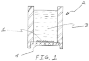
- FIG. 1 shows a cross-sectional view that depicts a device that does not integrate medium mixing equipment, medium perfusion equipment, or gas pumping equipment and that can be used to culture cancer cells at high density and study the ability of T cells to kill cancer cells and persist in that effort.
- Cancer cells 1 reside at the bottom of static cell culture device 2. The top is not shown but can be as simple as a cover traditionally associated with multiple well plates or can be more sophisticated including closed and configured for automated access.
- Medium 3 resides within cancer cell culture device 2.
- Bottom 4 of the device is comprised of gas permeable material, preferably silicone. Modifying the surface that cells will contact on the bottom of the compartment, such as by texturing, can be undertaken to allow the cancer cells to exist at a high density state in order to simulate a tumor.
- Surface texture can take the form of grooves, pockets, roughened areas, and the like. In essence, when bottom surface is not smooth, for each square centimeter of footprint relative to a device with a smooth surface, it can increase the surface area that cancer cells can come in contact with and facilitate an increase in cells per square centimeter of the compartment bottom.
- a matrix can also be used for the culture of cells at high density or more natural physical configuration. A matrix is often used to culture cells in what is commonly referred to as three dimensions. The matrix can be attached to the bottom surface but does not need to be attached to the bottom surface.
- Matrix material can consist of any material known by artisans to allow cells to be culture in a state that allows cells to reside in close contact and/or integrate within the matrix, including naturally occurring or synthetic material such as AlgiMatrix TM , collagen, fibronectin, plastic, sintered ceramic are among the many choices available. Such material, when the bottom is gas permeable, should strike a balance between allowing cells to reside in close contact (such as when cancer cells are used to simulate a tumor) and allowing oxygen to reach the cells. Thus, preferably the matrix is not a solid substance.
- This apparatus overcomes the limitations of traditional in vitro culture devices such as the AlgiMatrix TM 3D Culture System 24-well plate (Gibco Catalog No. 12684-023). By providing superior oxygenation via the gas permeable bottom and providing a large volume of medium T cells can be added to the device and long term assessments of their cancer killing capacity can be made. By allowing the ratio of the medium volume to footprint of the bottom to exceed that of the AlgiMatrix TM 3D Culture System 24-well plate, the device can function for longer durations with many advantages as will be shown.
- the footprint of the bottom is the determined by calculating the surface area of the bottom as if the bottom surface was smooth, thereby avoiding the inclusion of texture, growth matrices, or other forms of adding surface area.
- the medium volume to bottom footprint ratio exceeds that of the AlgiMatrix TM 3D Culture System 24-well plate.
- the medium volume to bottom footprint ratio is at least 2 and preferred 2, 3, 4, 5, 6, 7, 8, 9, 10, 11, 12, 13, 14, 15 or any number in between.
- the bottom is preferably comprised of silicone.
- at least the walls should be tinted in color.
- the bottoms can preferably also be tinted in color or both the walls and the bottoms can be tinted in color.
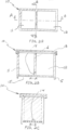
- FIG. 2A shows a top view of compartmentalized device 10, which includes two compartments. For clarity, the top is removed. Although the perimeter of each compartment is shown as square, they can be any shape and each compartment need not have the same shape or surface area.
- FIG. 2B which is a cross-sectional view A-A of FIG. 2A , passage 14 connects compartment 11 to adjacent to compartment 12. In this depiction, the compartments are shown with top 13. Top 13 can be similar to the top of a traditional multiple well plate.
- the bottom of the compartments can be gas impermeable or gas permeable. If gas permeable, the material should be preferably liquid impermeable.
- top 13 need not allow a gap for gas transfer to the compartments and can be sealed to the device to minimize contamination risk.
- top 13 is shown elevated in a similar manner as with the top of a conventional multi well plate.
- Feet 5 can be used to elevate the bottom of the compartments. This can serve more than one purpose. For example, if there is a desired to assess the contents of the compartment by way of the bottom (such as by use of an inverted microscope), the feet can prevent the bottom from becoming scratched or otherwise diminished in its ability to facilitate such an assessment.
- FIG. 2C shows section B-B of FIG. 2A .
- passage 14 is an opening in the wall that separates adjacent compartments 11 and 12. Passage 14 can be any opening that allows the contents of one compartment to communicate with another.
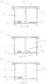
- FIG. 3A, FIG. 3B, and FIG. 3C show an example of how compartmentalized device 10, previously described and shown in FIG. 2A, FIG. 2B, and FIG. 2C , can be used.
- This device configuration allows assessment of the capability of T cells to recognize chemokine gradients, follow the gradient, find cancer cells, initiate cancer cell killing, and persist in that effort.
- cancer cells 16 reside in compartment 11 and T cells 18 reside in compartment 12.
- Arrow 20 shows the direction that chemokine secreted by cancer cells 16 moves through passage 14 as it travels from an area of higher concentration to an area of lower concentration.
- FIG. 3B shows the direction that T cells 18 migrate through passage 14 as they seek the source of the chemokine, moving from an area of lower chemokine concentration to an area of higher chemokine concentration.
- FIG. 3C shows how T cells 18 have migrated into compartment 11 in search of cancer cells 16. For clarity, the presence of medium has not been shown. This device configuration allows assessment of the capability of T cells to recognize chemokine gradients, follow the gradient, find cancer cells, initiate cancer cell killing, and persist in that effort.
- design attributes can be used to alter performance of the device and optimize it for a particular application. Examples can help explain how design attributes can be altered to make the performance of the device well suited to specific applications.
- One such example is an application in which the user of the device seeks to assess the capacity of T cells to find and kill cancer cells.
- one important aspect of the device is the geometry of the bottom of each compartment. In the compartment where cancer cells reside, they preferably grow to high density in order to simulate a tumor. In the areas of the device where cancer cells do not reside, a design goal should be to create an environment where the T cells are not impeded from migrating to the cancer cell location. Therefore, the surface that T cells will migrate across should be flat and not textured.
- a smooth surface finish that has an even and regular consistency, free from projections, lumps, or indentations that are easily perceptible is preferred.
- SPE Society of Plastic Engineers
- the surfaces across which cells will migrate are generally horizontal when the device is in use to minimize the possibility of cells having to travel uphill or the possibility of cells gravitating downhill. Either of these conditions could mislead a researcher into thinking the T cells are moving faster or slower than they actually would have if the surface were horizontal.
- the intention is for the T cells to move by chemokine stimulation so they can be assessed in terms of their capacity to move towards, and find, cancer cells.
- the design intent is to minimize unwanted forces that can act to move the T cells to the cancer cells or diminish the capacity of the T cells to migrate to the cancer cells.
- Skilled artisans should be aware that creating a perfectly horizontal surface is not likely, but surfaces similar to what are common in a traditional multiple well plate or commercially available G-Rex ® devices are suitable. Unwanted forces not only include the impact of gravity, they include the momentum of medium when the device is moved. It will be described in more detail how various passage designs and passage locations can minimize the effects of momentum.
- material that is expected to make contact with cells during their anticipated migration path is preferably hydrophobic so that it can facilitate cell migration. Stated differently, when cell migration is desired, the material in contact with the migrating cells should not be one that cells can attach to.
- each compartment may be made of any material used in cell culture devices and need not be gas permeable.
- materials include polystyrene of the thickness typically found in traditional multiwell plates for example.
- gas permeable materials in the bottom can create advantages as will be further described.
- Such material can be any membrane, film, or material used for gas permeable cell culture devices, such as silicone, flouroethylenepolypropylene, polyolefin, polystyrene, and ethylene vinyl acetate copolymer.
- the gas permeable material should be selected based on a variety of characteristics including gas permeability, moisture vapor transmission, capacity to be altered for desired cell interaction with cells, optical clarity, physical strength, and the like.
- Silicone is s preferred choice. It has excellent oxygen permeability, can allow optical observation, is not easily punctured, typically does not bind the cells to it, and can be easily fabricated into a wide variety of shapes suitable for the present invention.
- the height of the walls can dictate how much medium is allowed to reside in the device. Adding medium provides a larger source of substrates, and a larger sink for waste products. By increasing wall height and increasing the volume of medium that can exist in a compartment, it can have the effect of reducing feeding frequency, thereby reducing shifts in the concentration of solutes and substances in the medium. It can also have the effect of increasing the number of cells residing per square centimeter of device footprint.
- FIG. 4 shows a top view of a compartmentalized device with three compartments. For clarity, material not related to the boundaries of the compartments and the passages between compartments is not shown.
- This configuration can be used to assess the ability for differing populations of T cells to recognize various types of cancer. For example, cancer cells from one type of cancer can reside in compartment 24 of compartmentalized device 23. A particular population of T cells can reside in compartment 25 and a different population of T cells can reside in compartment 26. As cancer cells secrete chemokine signals, the type of T cells best able to respond and migrate to the cancer cells can be observed. Such an evaluation can be useful for example when evaluating T cell populations that have each been conferred with different attributes by genetic engineering. With this configuration, the genetically engineered T cell population that migrates most quickly to the cancer cells can help with the assessment of how well the genetically engineered attributes are expected to function in vivo. The killing capacity can also be assessed.
- compartment 25 and compartment 26 are created with the thought of providing them we identical geometry and material so that any differences in T cell response are attributable to the T cells and not the geometry or the type of material within the compartments.
- identical geometry and material between compartment 25 and compartment 26 is preferred.
- a key attribute is the configuration of passage or passages between compartments. Skilled artisans should be advised that there need not be just one passage between compartments. In this depiction, just one passage is shown for clarity.
- the passage, or passages, between compartment 25 and compartment 24 are configured with identical geometry to the passage, or passages, between compartment 26 and compartment 24. An important consideration when designing the passage(s) is to place them in the same relation to compartment 24. For example, in FIG.
- passage 27 is in the center of the wall that separates compartment 25 from compartment 24 and passage 28 is in the center of the wall that separates compartment 26 from compartment 24. Assuming the cancer cells and T cells are uniformly distributed throughout their respective compartments, this helps ensure chemokine signals reach the T cells at about the same time with about the same concentration of the signal.
- An alternative application for the geometry shown in FIG. 4 would be to place the T cells in compartment 24 and then two different types of cancer cells with in compartments 25 and compartment 26.
- the T cells can be evaluated to their response and movement towards the different cancer types.
- Such an application may be particularly beneficial when T cell populations comprised of T cells that recognize more than one tumor associated antigens are assessed for their ability to recognize different types of tumor like cancer cell populations.
- actual tumor fragments can be used in lieu of cancer cells.
- FIG. 5A, FIG. 5B, and FIG. 5C each show a perspective views of alternative configurations of a six compartment device of the present invention.
- the passage(s) between various compartments can be configured in a variety of patterns to allow migratory substances and/or microorganisms such as chemokine and/or cells to travel between compartments.
- arrow 29 indicates the path of migration when the migration begins in compartment 30 and ends where the arrowhead of arrow 29 terminates.
- Specific passage geometry is not shown in FIG. 5A, FIG. 5B, and FIG.
- each arrow takes one or more turns.
- the pathway for signal has at least one turn as for example shown in FIG. 5A , more preferable more than one turn as shown for example in FIG. 5B , and even more preferably makes a turn in each compartment that is not a source of the signal or a final destination of the signal as shown for example in FIG. 5C .
- FIG. 6 shows a circular configuration which includes compartments that are pie shaped. For clarity just an outline of the compartments and passages are shown.
- compartment 33 is connected to compartment 34 by passage 37
- compartment 34 is connected to compartment 35 by passage 36
- compartment 35 is connected to compartment 33 by passage 38.
- each compartment is in contact with its adjacent compartments by passages.
- FIG. 7 shows a circular configuration which includes compartments that are pie shaped. For clarity just an outline of the compartments and passages are shown. Within compartmentalized device 40, compartment 41, compartment 42, and compartment 43 are all connected by passage 44. In the case where it is deemed advantageous to have more than two compartment connected by just one passage, this is one illustrative embodiment showing how that can be achieved.
- FIG. 8 shows an embodiment of the compartmentalized device that is subdivided into compartments that are not symmetrical.
- Compartmentalized device 46 includes compartment 47, compartment 48, and compartment 49, and compartment 50.
- Passage 51, passage 52, passage 53 allow transport of substances between compartment 49 and compartment 50.
- the locations of the passages relative to the center point of the device vary and can increase the migratory pathway without increasing the size of the device footprint.
- the shape, quantity, and orientation of the passage(s) that separate compartments can impact performance. Their design should strike a balance between allowing elements within the contents of the device to pass from compartment to compartment with the need to minimize physical forces from propelling such elements from compartment to compartment. For example, if T cells are being monitored for their capacity to find cancer cells, the very act of moving the device to monitor such an event should not facilitate that event.
- the number of passages between compartments need not be limited to just one. One, two, three, four, five, six or any number of passages can be used.
- the design of the passage, or passages, between wells can also affect T cell migration.
- the capacity of medium to move through the passage from one compartment to the next should be minimized to prevent the momentum of medium from carrying T cells from one compartment to another or from carrying cancer cells from one compartment to another. This can be accomplished in a variety of ways.
- FIG. 9 shows one configuration of the passage that can be used to minimize the movement of medium from compartment to compartment.
- Wall 58 and wall 59 of passage 56 do not cut a perpendicular path through compartment wall 55.
- wall 60 and wall 61 of passage 57 do cut a perpendicular path through compartment wall 55.
- passage 56 can be used to create resistance to medium momentum during device handling.
- FIG. 10 shows another configuration of how the passage that can be used to minimize the movement of medium from compartment to compartment.
- Passage 63 does not cut a perpendicular path through compartment wall 62.
- passage 63 includes two right angle turns within compartment wall 62. Artisans are encouraged to recognize that at least one turn of any angle in a passage can be used to limit the force of momentum from driving substances through a compartment wall.
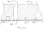
- FIG. 11 shows how passages can be of any shape and can remove any amount of material from a compartment wall that is desired for a particular application.
- passage 65 has a rectangular
- passage 67 has a rectangular shape with a circular shape at its top
- passage 68 has a triangular shape.
- Passage 66 is a slot that forms a complete break in compartment wall 69.
- Compartment wall 69 is mated to bottom 70.
- compartment wall is molded as one piece with bottom, it may be advantageous to mold a slot that completely breaks the compartment wall.
- a second component can be attached to the compartment wall to block any portion of the slot that is desired.
- the compartment wall would include a first wall with an opening and a wall component that restricts the opening.
- the size of the first opening would be reduced by the wall component. Artisans are encouraged to recognize that more than one passage can be used in a given compartment wall and when so toing, each passage can have a different shape and/or size and/or cross-sectional area to suit any given application.
- Passages need not be permanently open. They can include a closure that prevents contents from a compartment from passing through the wall. The closure can be opened when it is desirable to allow contents of a compartment to pass through the passage.
- the novel device provides benefits for the study of cancer cells when compared to a commonly used conventional in vitro device and when comparted to SCID mice.
- Evaluations were undertaken to determine if the compartmentalized device of the present invention could maintain cancer cells in a superior manner to a standard in vitro tool that is typically used to cultivate cancer cells. The evaluations also made comparison to the in vivo culture of cancer cells in a SCID mouse.
- a prototype of one embodiment of compartmentalized device was created.
- the device in which cancer cells were placed had square bottom with a surface area of 12 cm 2 that was comprised of silicone with a thickness between 0.008 to 0.012 inches.
- the walls of the compartment were of a height that allowed medium to reside at a height of 5 cm and medium resided directly above the bottom.
- the prototype was comparted to the AlgiMatrix TM 3D Culture System 24-well plate (Gibco Catalog No. 12684-023) and to SCID mice, which are commonly used for cancer cell studies.
- AlgiMatrix TM 3D Culture System 24-well plate received 1x10 6 CAPAN-1 cancer cells.
- CAPAN-1 CAPAN-1 cancer cells.
- three scaffolds were removed and distributed separately to each of three prototypes.
- each prototype now had one AlgiMatrix TM bioscaffold engrafted with cancer cells.
- Each prototype received 60 ml of medium, and each of the remaining three wells of the AlgiMatrix TM 3D Culture System plate received completely fresh medium in the amount of 2 ml per well.
- Twenty SCID mice (n 20) each received 1x10 6 CAPAN-1 cancer cells. Growth of the cancer cells was monitored by bioluminescence imaging.
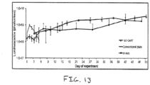
- FIG. 12 shows a representative example of cancer cells proliferating in a SCID mouse and in the prototype as represented by the bioluminescence signal progressively increasing over a 28-day time period.
- FIG. 12 also compares cancer cell growth of the prototypes vs. the SCID mice vs. the AlgiMatrix TM 3D Culture System plate. Cancer cell proliferation in the prototypes was similar to that observed in SCID mice.
- the novel device has the ability to assess prolonged anti-tumor effects.
- CAR T chimeric antigen receptors
- CAR T cell administration in SCID mice resulted in a decrease in tumor signal which was sustained for a period of two weeks, indicating the infused CAR T cells were killing the CAPAN-1 cancer cells and were thus able to produce anti-tumor effects.
- the right hand panel of FIG. 14 shows how the same anti-tumor effects was seen when CAR T cells were added directly to the prototype. This demonstrates how the novel prototype can be a suitable surrogate to SCID mice, thereby allowing researchers to rely more frequently upon use of an in vitro device instead of SCID mice.
- the present invention can allow chemokine gradients to be established throughout the device.
- a prototype test device was configured with six compartments. Each compartment had a square bottom with a 12 cm 2 surface area. Walls allowed medium to reside directly above the bottom of each compartment at a height of 5 cm. The compartments were arranged three compartments long and two compartments in a similar pattern to a traditional six well plate. Small passage openings between various adjoining walls of the compartments allowed chemokine to move between compartments. The openings were approximately 2 mm x 2 mm and at the base of the center of the walls between connected compartments.
- the top panel of FIG. 15 shows arrows indicating the expected gradient path created by the passages between compartments.
- the design was a maze pattern intended to allow the device to be moved (e.g., into an incubator) without causing a disruption of the chemokine gradient.
- one compartment (designated as well #1 in FIG. 15 ) of the device was spiked with 24ug of recombinant MCP1.
- the chemokine concentrations were determined in wells 1 through 6 at 24, 48 and 72 hours.
- the bottom panel of FIG. 15 shows the concentration of MCP1 in the different wells at the indicated time points.
- MCP1 levels progressively decreased in well 1 over time and became detectable in an increasing fashion in compartments along the path allowed by passages.
- Data indicate the present invention can be used to distinguish between first and second generation CAR T cells.
- Example 3 The prototype design of Example 3 was used to evaluate the ability to target pancreatic cancer cells. 60 ml of medium was present in each well. Results are shown in FIG. 16 .
- a culture of luminescence CAPAN-1 cancer cells was established in compartment 6 in each of two prototypes. First generation CAR T cells were placed in compartment number 1 of each of one prototype. Second generation CAR T cells were placed in compartment number 1 of the other prototype. In both prototypes, CAR T cells followed the chemokine gradient expressed by the CAPAN-1 cancer cells (migration data not shown) and reached the CAPAN-1 cancer cells.
- both first and second generation CAR T variants demonstrated the ability to decrease cancer cell luminescence, suggesting they were equally effective at killing the CAPAN-1 cancer cells and it appeared that on about Day-12 the cancer cells were nearly eliminated.
- the second generation CAR T cells began to show dramatically better persistence and were able to continue anti-tumor activity while the first generation CAR T cells lost their cancer killing capacity and the cancer cells were able to recover. It is important to note that with conventional in vitro devices it would not be possible to distinguish between these CAR T generations for two important reasons. First, conventional in vitro devices do not allow migration and must initiate the experiment with the T cells in the same compartment as the cancer cells. Second, as shown previously, conventional in vitro devices cannot sustain cultures for more than two days (see FIG.
- a device with at least two compartments should be configured with a passage between the compartments to allow signals and cells to pass from compartment to compartment.
- the use of gas permeable material can allow medium exchange to be eliminated for at least up to 28 days.
Landscapes
- Health & Medical Sciences (AREA)
- Wood Science & Technology (AREA)
- Organic Chemistry (AREA)
- Life Sciences & Earth Sciences (AREA)
- Engineering & Computer Science (AREA)
- Bioinformatics & Cheminformatics (AREA)
- Chemical & Material Sciences (AREA)
- Zoology (AREA)
- Biomedical Technology (AREA)
- Sustainable Development (AREA)
- Microbiology (AREA)
- Biotechnology (AREA)
- Biochemistry (AREA)
- General Engineering & Computer Science (AREA)
- General Health & Medical Sciences (AREA)
- Genetics & Genomics (AREA)
- Clinical Laboratory Science (AREA)
- Apparatus Associated With Microorganisms And Enzymes (AREA)
- Measuring Or Testing Involving Enzymes Or Micro-Organisms (AREA)
- Micro-Organisms Or Cultivation Processes Thereof (AREA)
Claims (12)
- Appareil de culture cellulaire (10, 23, 46) destiné à contenir un volume de milieu, comprenant :trois compartiments ou plus (24, 25, 26, 30, 47, 48, 49, 50), chaque compartiment étant séparé par une paroi (55, 62, 69), un compartiment étant approprié pour une source d'un signal sécrété par des cellules et un autre compartiment étant approprié pour contenir des cellules pour répondre à la source du signal sécrété par des cellules,les trois compartiments ou plus ayant des fonds (15, 70) qui sont plats,dans lequel l'appareil de culture cellulaire ne comprend pas d'équipement de mélange de milieu, d'équipement de perfusion de milieu ou d'équipement de pompage à gaz ;au moins un passage (14, 27, 28, 51, 52, 53) à travers la paroi entre des compartiments, le au moins un passage étant une ouverture dans la paroi reliant le fond de compartiments adjacents et permettant au contenu d'un compartiment d'être en communication avec un autre,dans lequel les passages forment un trajet de migration entre le compartiment approprié pour une source d'un signal sécrété par des cellules et le compartiment pour contenir des cellules appropriées pour répondre à la source du signal sécrété par des cellules, le trajet de migration présentant plus d'un tour ; etles fonds des trois compartiments ou plus sont perméables aux gaz et sont dans un plan horizontal ; etdans lequel l'appareil présente un rapport entre le volume de milieu et l'empreinte de fond d'au moins 2.
- Appareil selon l'une quelconque des revendications précédentes, dans lequel au moins un compartiment comprend une matrice.
- Appareil selon la revendication 3, dans lequel la matrice est fixée au fond.
- Appareil selon la revendication 3 ou la revendication 4, dans lequel la matrice n'est pas une substance solide.
- Appareil selon l'une quelconque des revendications précédentes, dans lequel au moins une paroi d'au moins un compartiment est teintée en couleur.
- Appareil selon l'une quelconque des revendications précédentes, dans lequel le fond d'au moins un compartiment est teinté en couleur.
- Appareil selon l'une quelconque des revendications précédentes, dans lequel le rapport entre le volume de milieu et l'empreinte de fond est inférieur ou égal à 15.
- Appareil selon l'une quelconque des revendications précédentes, dans lequel le fond d'au moins un compartiment est carré ou rectangulaire.
- Appareil selon l'une quelconque des revendications précédentes, comprenant six compartiments.
- Procédé d'évaluation de lymphocytes T comprenant l'étape consistant à :
ajouter des cellules T (18), des cellules cancéreuses (16) et un milieu dans un appareil de culture cellulaire selon l'une quelconque des revendications précédentes, dans lequel des cellules cancéreuses sont ajoutées à un compartiment qui diffère du compartiment auquel les cellules T sont ajoutées. - Procédé selon la revendication 10, dans lequel au moins un compartiment comprend une matrice et des cellules cancéreuses sont ajoutées à ce compartiment.
- Procédé selon la revendication 10 ou la revendication 11, dans lequel, à un certain moment après l'ajout des cellules T, les cellules T migrent vers l'emplacement des cellules cancéreuses.
Priority Applications (1)
| Application Number | Priority Date | Filing Date | Title |
|---|---|---|---|
| EP24167729.3A EP4446402A3 (fr) | 2015-05-08 | 2016-05-09 | Procédés de culture améliorés et dispositifs de test |
Applications Claiming Priority (2)
| Application Number | Priority Date | Filing Date | Title |
|---|---|---|---|
| US201562158583P | 2015-05-08 | 2015-05-08 | |
| PCT/US2016/031544 WO2016183037A1 (fr) | 2015-05-08 | 2016-05-09 | Procédés de culture améliorés et dispositifs de test |
Related Child Applications (2)
| Application Number | Title | Priority Date | Filing Date |
|---|---|---|---|
| EP24167729.3A Division EP4446402A3 (fr) | 2015-05-08 | 2016-05-09 | Procédés de culture améliorés et dispositifs de test |
| EP24167729.3A Division-Into EP4446402A3 (fr) | 2015-05-08 | 2016-05-09 | Procédés de culture améliorés et dispositifs de test |
Publications (3)
| Publication Number | Publication Date |
|---|---|
| EP3294864A1 EP3294864A1 (fr) | 2018-03-21 |
| EP3294864A4 EP3294864A4 (fr) | 2019-01-02 |
| EP3294864B1 true EP3294864B1 (fr) | 2024-09-25 |
Family
ID=57222414
Family Applications (2)
| Application Number | Title | Priority Date | Filing Date |
|---|---|---|---|
| EP24167729.3A Withdrawn EP4446402A3 (fr) | 2015-05-08 | 2016-05-09 | Procédés de culture améliorés et dispositifs de test |
| EP16793345.6A Active EP3294864B1 (fr) | 2015-05-08 | 2016-05-09 | Procédés de culture améliorés et dispositifs de test |
Family Applications Before (1)
| Application Number | Title | Priority Date | Filing Date |
|---|---|---|---|
| EP24167729.3A Withdrawn EP4446402A3 (fr) | 2015-05-08 | 2016-05-09 | Procédés de culture améliorés et dispositifs de test |
Country Status (7)
| Country | Link |
|---|---|
| US (3) | US11613725B2 (fr) |
| EP (2) | EP4446402A3 (fr) |
| JP (3) | JP7271175B2 (fr) |
| CN (1) | CN108076642A (fr) |
| AU (3) | AU2016261504B2 (fr) |
| CA (1) | CA2985350A1 (fr) |
| WO (1) | WO2016183037A1 (fr) |
Families Citing this family (5)
| Publication number | Priority date | Publication date | Assignee | Title |
|---|---|---|---|---|
| WO2021183687A2 (fr) | 2020-03-10 | 2021-09-16 | Cellares Corporation | Systèmes, dispositifs et procédés de traitement de cellules |
| CN114574365A (zh) * | 2022-03-21 | 2022-06-03 | 连云港市质量技术综合检验检测中心 | 一种动物细胞分离纯化用培养皿装置 |
| US12399193B2 (en) | 2023-05-05 | 2025-08-26 | Cellares Corporation | Systems, devices, and methods for combined cell processes |
| AU2024281699A1 (en) * | 2023-05-31 | 2025-12-18 | Wilson Wolf Manufacturing, LLC | Long term potency assays for cell and gene-modified cell therapy |
| US12497587B2 (en) | 2023-08-21 | 2025-12-16 | Cellares Corporation | Bioreactors and methods of their use in automatic cell processing systems |
Citations (6)
| Publication number | Priority date | Publication date | Assignee | Title |
|---|---|---|---|---|
| EP0620274A1 (fr) * | 1992-09-16 | 1994-10-19 | Universidade De Santiago De Compostela | Plaquette pour cultures cellulaires avec systeme de diffusion laterale des molecules a travers une membrane barriere |
| US6908767B2 (en) * | 2000-09-19 | 2005-06-21 | Augustinus Bader | Method and device for growing and/or treating cells |
| US20100103410A1 (en) * | 2008-09-22 | 2010-04-29 | Arkadiy Silbergleit | Devices and methods for visualization of a sample in a microplate |
| US20110182870A1 (en) * | 2009-08-24 | 2011-07-28 | Leen Ann M | Generation of ctl lines with specificity against multiple tumor antigens or multiple viruses |
| US20130171682A1 (en) * | 2010-01-21 | 2013-07-04 | Emd Millipore Corporation | Cell Culture and Gradient Migration Assay Methods and Devices |
| WO2014121289A2 (fr) * | 2013-02-04 | 2014-08-07 | The University Of Kansas | Dispositif mimant la métastase |
Family Cites Families (16)
| Publication number | Priority date | Publication date | Assignee | Title |
|---|---|---|---|---|
| US20050170503A1 (en) | 1997-02-27 | 2005-08-04 | University Of Pittsburgh | In vitro induction of antigen-specific T-cells using dendritic cell-tumor cell or dendritic cell-viral cell derived immunogens |
| JPH11127843A (ja) | 1997-10-27 | 1999-05-18 | Sumitomo Bakelite Co Ltd | 培養用着色容器 |
| JP2000184880A (ja) * | 1998-10-14 | 2000-07-04 | Kanegafuchi Chem Ind Co Ltd | ガン細胞特異的傷害性t細胞の増殖・活性化誘導方法及びそれに用いるデバイス |
| EP1168924A4 (fr) | 1999-03-31 | 2002-09-04 | Univ Pittsburgh | Induction in vitro de cellules t specifiques a un antigene a l'aide d'immunogenes derives de cellules dendritiques-cellules tumorales ou de cellules dendritiques-cellules virales |
| CA2466881A1 (fr) | 2001-11-28 | 2003-06-05 | Sandoz Gmbh | Procede de culture de cellules |
| US7470428B2 (en) * | 2002-01-30 | 2008-12-30 | The Brigham And Women's Hospital, Inc. | Compositions and methods related to TIM-3, a Th1-specific cell surface molecule |
| CN101120083B (zh) * | 2003-10-08 | 2013-03-27 | 威尔森沃尔夫制造公司 | 利用透气性材料进行细胞培养的方法及装置 |
| US8551770B2 (en) * | 2006-07-07 | 2013-10-08 | University Of Miami | Enhanced oxygen cell culture platforms |
| US9175254B2 (en) * | 2006-07-07 | 2015-11-03 | University Of Miami | Enhanced oxygen cell culture platforms |
| US20080176318A1 (en) | 2006-12-07 | 2008-07-24 | Wilson John R | Highly efficient devices and methods for culturing cells |
| DE102008031265B4 (de) * | 2008-07-02 | 2012-12-13 | Volker Lob | Zellchipsystem mit Ableitkamin |
| KR20100117869A (ko) * | 2009-04-27 | 2010-11-04 | 한국산업기술대학교산학협력단 | 세포 배양 용기 |
| CN101974487A (zh) * | 2010-11-12 | 2011-02-16 | 苏州大学 | 具有最高迁移效率的神经干细胞的制备方法及其应用 |
| KR101369084B1 (ko) * | 2011-07-20 | 2014-03-03 | 울산대학교 산학협력단 | 세포 배양용 마이크로 유동성 플랫폼 및 이를 이용한 세포 배양방법 |
| JP2015517804A (ja) * | 2012-04-01 | 2015-06-25 | イー・エム・デイー・ミリポア・コーポレイシヨン | 細胞培養及び傾斜移動アッセイ方法及び装置 |
| US9683207B2 (en) * | 2012-05-01 | 2017-06-20 | FiberCell Production Solutions LLC | Method for growing cells in hollow fibers |
-
2016
- 2016-05-09 CA CA2985350A patent/CA2985350A1/fr active Pending
- 2016-05-09 JP JP2018510703A patent/JP7271175B2/ja active Active
- 2016-05-09 WO PCT/US2016/031544 patent/WO2016183037A1/fr not_active Ceased
- 2016-05-09 US US15/150,381 patent/US11613725B2/en active Active
- 2016-05-09 EP EP24167729.3A patent/EP4446402A3/fr not_active Withdrawn
- 2016-05-09 EP EP16793345.6A patent/EP3294864B1/fr active Active
- 2016-05-09 CN CN201680033685.7A patent/CN108076642A/zh active Pending
- 2016-05-09 AU AU2016261504A patent/AU2016261504B2/en active Active
-
2021
- 2021-05-10 AU AU2021202948A patent/AU2021202948B2/en active Active
-
2022
- 2022-11-04 JP JP2022177177A patent/JP7544787B2/ja active Active
-
2023
- 2023-03-24 US US18/126,051 patent/US11891595B2/en active Active
- 2023-08-16 AU AU2023216819A patent/AU2023216819B2/en active Active
- 2023-12-29 US US18/400,103 patent/US20240132820A1/en active Pending
-
2024
- 2024-08-22 JP JP2024140751A patent/JP2024164143A/ja active Pending
Patent Citations (6)
| Publication number | Priority date | Publication date | Assignee | Title |
|---|---|---|---|---|
| EP0620274A1 (fr) * | 1992-09-16 | 1994-10-19 | Universidade De Santiago De Compostela | Plaquette pour cultures cellulaires avec systeme de diffusion laterale des molecules a travers une membrane barriere |
| US6908767B2 (en) * | 2000-09-19 | 2005-06-21 | Augustinus Bader | Method and device for growing and/or treating cells |
| US20100103410A1 (en) * | 2008-09-22 | 2010-04-29 | Arkadiy Silbergleit | Devices and methods for visualization of a sample in a microplate |
| US20110182870A1 (en) * | 2009-08-24 | 2011-07-28 | Leen Ann M | Generation of ctl lines with specificity against multiple tumor antigens or multiple viruses |
| US20130171682A1 (en) * | 2010-01-21 | 2013-07-04 | Emd Millipore Corporation | Cell Culture and Gradient Migration Assay Methods and Devices |
| WO2014121289A2 (fr) * | 2013-02-04 | 2014-08-07 | The University Of Kansas | Dispositif mimant la métastase |
Also Published As
| Publication number | Publication date |
|---|---|
| JP7271175B2 (ja) | 2023-05-11 |
| JP2023012529A (ja) | 2023-01-25 |
| AU2021202948A1 (en) | 2021-06-10 |
| AU2016261504B2 (en) | 2021-02-11 |
| AU2023216819B2 (en) | 2025-07-17 |
| US11613725B2 (en) | 2023-03-28 |
| EP3294864A4 (fr) | 2019-01-02 |
| US20160326478A1 (en) | 2016-11-10 |
| CA2985350A1 (fr) | 2016-11-17 |
| JP7544787B2 (ja) | 2024-09-03 |
| AU2023216819A1 (en) | 2023-09-07 |
| JP2024164143A (ja) | 2024-11-26 |
| EP4446402A2 (fr) | 2024-10-16 |
| JP2018518987A (ja) | 2018-07-19 |
| CN108076642A (zh) | 2018-05-25 |
| US20240132820A1 (en) | 2024-04-25 |
| US20230227762A1 (en) | 2023-07-20 |
| AU2021202948B2 (en) | 2023-05-25 |
| EP4446402A3 (fr) | 2025-01-08 |
| EP3294864A1 (fr) | 2018-03-21 |
| AU2016261504A1 (en) | 2017-12-14 |
| WO2016183037A1 (fr) | 2016-11-17 |
| US11891595B2 (en) | 2024-02-06 |
Similar Documents
| Publication | Publication Date | Title |
|---|---|---|
| US11891595B2 (en) | Culture methods and devices for testing | |
| Tocchio et al. | Magnetically guided self‐assembly and coding of 3D living architectures | |
| KR102527308B1 (ko) | 3d 세포 응집체의 생성 및 배양을 위한 장치 및 방법 | |
| US20190322969A1 (en) | Devices and methods for generation and culture of 3d cell aggregates | |
| CN103476920B (zh) | 处理细胞和相关结构的设备及方法 | |
| KR20140113139A (ko) | 세포 스페로이드 배양판 | |
| JP6035343B2 (ja) | 毒性スクリーニング方法 | |
| Randall et al. | Three-dimensional microwell arrays for cell culture | |
| DE202011110503U1 (de) | Hängetropfenvorrichtungen und -systeme | |
| Cochet-Escartin et al. | Hypoxia triggers collective aerotactic migration in Dictyostelium discoideum | |
| CN107109328A (zh) | 细胞培养插入件 | |
| Lin et al. | Spatial manipulation with microfluidics | |
| Luhur et al. | Generating and working with Drosophila cell cultures: Current challenges and opportunities | |
| García Alonso et al. | Advances in microfluidics‐based technologies for single cell culture | |
| CN102203241A (zh) | 细胞保存方法和细胞运输方法 | |
| Barozzi et al. | Emerging strategies in 3D culture models for hematological cancers | |
| Okumus et al. | Fluidic and microfluidic tools for quantitative systems biology | |
| KR20150051199A (ko) | 세포 스페로이드 배양판 | |
| Natesh et al. | Advances and challenges in human 3D solid tumor models | |
| CN102517214A (zh) | 一种评价细胞迁移行为的细胞培养器 | |
| US20220062895A1 (en) | Microfluidic Device And Method Of Assaying For Immune Cell Exhaustion Using Same | |
| Marinkovic | Self-organization of Saccharomyces cerevisiae colonies |
Legal Events
| Date | Code | Title | Description |
|---|---|---|---|
| STAA | Information on the status of an ep patent application or granted ep patent |
Free format text: STATUS: THE INTERNATIONAL PUBLICATION HAS BEEN MADE |
|
| PUAI | Public reference made under article 153(3) epc to a published international application that has entered the european phase |
Free format text: ORIGINAL CODE: 0009012 |
|
| STAA | Information on the status of an ep patent application or granted ep patent |
Free format text: STATUS: REQUEST FOR EXAMINATION WAS MADE |
|
| 17P | Request for examination filed |
Effective date: 20171204 |
|
| AK | Designated contracting states |
Kind code of ref document: A1 Designated state(s): AL AT BE BG CH CY CZ DE DK EE ES FI FR GB GR HR HU IE IS IT LI LT LU LV MC MK MT NL NO PL PT RO RS SE SI SK SM TR |
|
| AX | Request for extension of the european patent |
Extension state: BA ME |
|
| DAV | Request for validation of the european patent (deleted) | ||
| DAX | Request for extension of the european patent (deleted) | ||
| A4 | Supplementary search report drawn up and despatched |
Effective date: 20181130 |
|
| RIC1 | Information provided on ipc code assigned before grant |
Ipc: C12M 3/00 20060101AFI20181126BHEP Ipc: C12M 1/00 20060101ALI20181126BHEP Ipc: C12M 1/24 20060101ALI20181126BHEP Ipc: C12M 1/04 20060101ALI20181126BHEP |
|
| STAA | Information on the status of an ep patent application or granted ep patent |
Free format text: STATUS: EXAMINATION IS IN PROGRESS |
|
| 17Q | First examination report despatched |
Effective date: 20201126 |
|
| GRAP | Despatch of communication of intention to grant a patent |
Free format text: ORIGINAL CODE: EPIDOSNIGR1 |
|
| STAA | Information on the status of an ep patent application or granted ep patent |
Free format text: STATUS: GRANT OF PATENT IS INTENDED |
|
| INTG | Intention to grant announced |
Effective date: 20231005 |
|
| P01 | Opt-out of the competence of the unified patent court (upc) registered |
Effective date: 20231204 |
|
| P02 | Opt-out of the competence of the unified patent court (upc) changed |
Effective date: 20231214 |
|
| RAP3 | Party data changed (applicant data changed or rights of an application transferred) |
Owner name: WILSON WOLF MANUFACTURING, LLC |
|
| GRAJ | Information related to disapproval of communication of intention to grant by the applicant or resumption of examination proceedings by the epo deleted |
Free format text: ORIGINAL CODE: EPIDOSDIGR1 |
|
| STAA | Information on the status of an ep patent application or granted ep patent |
Free format text: STATUS: EXAMINATION IS IN PROGRESS |
|
| INTC | Intention to grant announced (deleted) | ||
| GRAP | Despatch of communication of intention to grant a patent |
Free format text: ORIGINAL CODE: EPIDOSNIGR1 |
|
| STAA | Information on the status of an ep patent application or granted ep patent |
Free format text: STATUS: GRANT OF PATENT IS INTENDED |
|
| INTG | Intention to grant announced |
Effective date: 20240422 |
|
| GRAS | Grant fee paid |
Free format text: ORIGINAL CODE: EPIDOSNIGR3 |
|
| GRAA | (expected) grant |
Free format text: ORIGINAL CODE: 0009210 |
|
| STAA | Information on the status of an ep patent application or granted ep patent |
Free format text: STATUS: THE PATENT HAS BEEN GRANTED |
|
| AK | Designated contracting states |
Kind code of ref document: B1 Designated state(s): AL AT BE BG CH CY CZ DE DK EE ES FI FR GB GR HR HU IE IS IT LI LT LU LV MC MK MT NL NO PL PT RO RS SE SI SK SM TR |
|
| REG | Reference to a national code |
Ref country code: GB Ref legal event code: FG4D |
|
| REG | Reference to a national code |
Ref country code: CH Ref legal event code: EP |
|
| REG | Reference to a national code |
Ref country code: DE Ref legal event code: R096 Ref document number: 602016089574 Country of ref document: DE |
|
| REG | Reference to a national code |
Ref country code: IE Ref legal event code: FG4D |
|
| REG | Reference to a national code |
Ref country code: SE Ref legal event code: TRGR |
|
| REG | Reference to a national code |
Ref country code: LT Ref legal event code: MG9D |
|
| PG25 | Lapsed in a contracting state [announced via postgrant information from national office to epo] |
Ref country code: NO Free format text: LAPSE BECAUSE OF FAILURE TO SUBMIT A TRANSLATION OF THE DESCRIPTION OR TO PAY THE FEE WITHIN THE PRESCRIBED TIME-LIMIT Effective date: 20241225 |
|
| PG25 | Lapsed in a contracting state [announced via postgrant information from national office to epo] |
Ref country code: GR Free format text: LAPSE BECAUSE OF FAILURE TO SUBMIT A TRANSLATION OF THE DESCRIPTION OR TO PAY THE FEE WITHIN THE PRESCRIBED TIME-LIMIT Effective date: 20241226 Ref country code: FI Free format text: LAPSE BECAUSE OF FAILURE TO SUBMIT A TRANSLATION OF THE DESCRIPTION OR TO PAY THE FEE WITHIN THE PRESCRIBED TIME-LIMIT Effective date: 20240925 |
|
| PG25 | Lapsed in a contracting state [announced via postgrant information from national office to epo] |
Ref country code: BG Free format text: LAPSE BECAUSE OF FAILURE TO SUBMIT A TRANSLATION OF THE DESCRIPTION OR TO PAY THE FEE WITHIN THE PRESCRIBED TIME-LIMIT Effective date: 20240925 |
|
| PG25 | Lapsed in a contracting state [announced via postgrant information from national office to epo] |
Ref country code: LV Free format text: LAPSE BECAUSE OF FAILURE TO SUBMIT A TRANSLATION OF THE DESCRIPTION OR TO PAY THE FEE WITHIN THE PRESCRIBED TIME-LIMIT Effective date: 20240925 |
|
| PG25 | Lapsed in a contracting state [announced via postgrant information from national office to epo] |
Ref country code: RS Free format text: LAPSE BECAUSE OF FAILURE TO SUBMIT A TRANSLATION OF THE DESCRIPTION OR TO PAY THE FEE WITHIN THE PRESCRIBED TIME-LIMIT Effective date: 20241225 |
|
| REG | Reference to a national code |
Ref country code: NL Ref legal event code: MP Effective date: 20240925 |
|
| PG25 | Lapsed in a contracting state [announced via postgrant information from national office to epo] |
Ref country code: RS Free format text: LAPSE BECAUSE OF FAILURE TO SUBMIT A TRANSLATION OF THE DESCRIPTION OR TO PAY THE FEE WITHIN THE PRESCRIBED TIME-LIMIT Effective date: 20241225 Ref country code: NO Free format text: LAPSE BECAUSE OF FAILURE TO SUBMIT A TRANSLATION OF THE DESCRIPTION OR TO PAY THE FEE WITHIN THE PRESCRIBED TIME-LIMIT Effective date: 20241225 Ref country code: LV Free format text: LAPSE BECAUSE OF FAILURE TO SUBMIT A TRANSLATION OF THE DESCRIPTION OR TO PAY THE FEE WITHIN THE PRESCRIBED TIME-LIMIT Effective date: 20240925 Ref country code: GR Free format text: LAPSE BECAUSE OF FAILURE TO SUBMIT A TRANSLATION OF THE DESCRIPTION OR TO PAY THE FEE WITHIN THE PRESCRIBED TIME-LIMIT Effective date: 20241226 Ref country code: FI Free format text: LAPSE BECAUSE OF FAILURE TO SUBMIT A TRANSLATION OF THE DESCRIPTION OR TO PAY THE FEE WITHIN THE PRESCRIBED TIME-LIMIT Effective date: 20240925 Ref country code: BG Free format text: LAPSE BECAUSE OF FAILURE TO SUBMIT A TRANSLATION OF THE DESCRIPTION OR TO PAY THE FEE WITHIN THE PRESCRIBED TIME-LIMIT Effective date: 20240925 |
|
| REG | Reference to a national code |
Ref country code: AT Ref legal event code: MK05 Ref document number: 1726658 Country of ref document: AT Kind code of ref document: T Effective date: 20240925 |
|
| PG25 | Lapsed in a contracting state [announced via postgrant information from national office to epo] |
Ref country code: NL Free format text: LAPSE BECAUSE OF FAILURE TO SUBMIT A TRANSLATION OF THE DESCRIPTION OR TO PAY THE FEE WITHIN THE PRESCRIBED TIME-LIMIT Effective date: 20240925 |
|
| PG25 | Lapsed in a contracting state [announced via postgrant information from national office to epo] |
Ref country code: IS Free format text: LAPSE BECAUSE OF FAILURE TO SUBMIT A TRANSLATION OF THE DESCRIPTION OR TO PAY THE FEE WITHIN THE PRESCRIBED TIME-LIMIT Effective date: 20250125 Ref country code: PT Free format text: LAPSE BECAUSE OF FAILURE TO SUBMIT A TRANSLATION OF THE DESCRIPTION OR TO PAY THE FEE WITHIN THE PRESCRIBED TIME-LIMIT Effective date: 20250127 |
|
| PG25 | Lapsed in a contracting state [announced via postgrant information from national office to epo] |
Ref country code: RO Free format text: LAPSE BECAUSE OF FAILURE TO SUBMIT A TRANSLATION OF THE DESCRIPTION OR TO PAY THE FEE WITHIN THE PRESCRIBED TIME-LIMIT Effective date: 20240925 Ref country code: SM Free format text: LAPSE BECAUSE OF FAILURE TO SUBMIT A TRANSLATION OF THE DESCRIPTION OR TO PAY THE FEE WITHIN THE PRESCRIBED TIME-LIMIT Effective date: 20240925 |
|
| PG25 | Lapsed in a contracting state [announced via postgrant information from national office to epo] |
Ref country code: ES Free format text: LAPSE BECAUSE OF FAILURE TO SUBMIT A TRANSLATION OF THE DESCRIPTION OR TO PAY THE FEE WITHIN THE PRESCRIBED TIME-LIMIT Effective date: 20240925 |
|
| PG25 | Lapsed in a contracting state [announced via postgrant information from national office to epo] |
Ref country code: EE Free format text: LAPSE BECAUSE OF FAILURE TO SUBMIT A TRANSLATION OF THE DESCRIPTION OR TO PAY THE FEE WITHIN THE PRESCRIBED TIME-LIMIT Effective date: 20240925 Ref country code: AT Free format text: LAPSE BECAUSE OF FAILURE TO SUBMIT A TRANSLATION OF THE DESCRIPTION OR TO PAY THE FEE WITHIN THE PRESCRIBED TIME-LIMIT Effective date: 20240925 |
|
| PG25 | Lapsed in a contracting state [announced via postgrant information from national office to epo] |
Ref country code: CZ Free format text: LAPSE BECAUSE OF FAILURE TO SUBMIT A TRANSLATION OF THE DESCRIPTION OR TO PAY THE FEE WITHIN THE PRESCRIBED TIME-LIMIT Effective date: 20240925 Ref country code: PL Free format text: LAPSE BECAUSE OF FAILURE TO SUBMIT A TRANSLATION OF THE DESCRIPTION OR TO PAY THE FEE WITHIN THE PRESCRIBED TIME-LIMIT Effective date: 20240925 |
|
| PG25 | Lapsed in a contracting state [announced via postgrant information from national office to epo] |
Ref country code: SK Free format text: LAPSE BECAUSE OF FAILURE TO SUBMIT A TRANSLATION OF THE DESCRIPTION OR TO PAY THE FEE WITHIN THE PRESCRIBED TIME-LIMIT Effective date: 20240925 Ref country code: IT Free format text: LAPSE BECAUSE OF FAILURE TO SUBMIT A TRANSLATION OF THE DESCRIPTION OR TO PAY THE FEE WITHIN THE PRESCRIBED TIME-LIMIT Effective date: 20240925 |
|
| REG | Reference to a national code |
Ref country code: DE Ref legal event code: R097 Ref document number: 602016089574 Country of ref document: DE |
|
| PGFP | Annual fee paid to national office [announced via postgrant information from national office to epo] |
Ref country code: DE Payment date: 20250416 Year of fee payment: 10 |
|
| PG25 | Lapsed in a contracting state [announced via postgrant information from national office to epo] |
Ref country code: DK Free format text: LAPSE BECAUSE OF FAILURE TO SUBMIT A TRANSLATION OF THE DESCRIPTION OR TO PAY THE FEE WITHIN THE PRESCRIBED TIME-LIMIT Effective date: 20240925 |
|
| PGFP | Annual fee paid to national office [announced via postgrant information from national office to epo] |
Ref country code: GB Payment date: 20250410 Year of fee payment: 10 |
|
| PGFP | Annual fee paid to national office [announced via postgrant information from national office to epo] |
Ref country code: BE Payment date: 20250422 Year of fee payment: 10 |
|
| PGFP | Annual fee paid to national office [announced via postgrant information from national office to epo] |
Ref country code: FR Payment date: 20250422 Year of fee payment: 10 |
|
| PGFP | Annual fee paid to national office [announced via postgrant information from national office to epo] |
Ref country code: CH Payment date: 20250601 Year of fee payment: 10 |
|
| PGFP | Annual fee paid to national office [announced via postgrant information from national office to epo] |
Ref country code: SE Payment date: 20250411 Year of fee payment: 10 |
|
| PLBE | No opposition filed within time limit |
Free format text: ORIGINAL CODE: 0009261 |
|
| STAA | Information on the status of an ep patent application or granted ep patent |
Free format text: STATUS: NO OPPOSITION FILED WITHIN TIME LIMIT |
|
| 26N | No opposition filed |
Effective date: 20250626 |
|
| PG25 | Lapsed in a contracting state [announced via postgrant information from national office to epo] |
Ref country code: HR Free format text: LAPSE BECAUSE OF FAILURE TO SUBMIT A TRANSLATION OF THE DESCRIPTION OR TO PAY THE FEE WITHIN THE PRESCRIBED TIME-LIMIT Effective date: 20240925 Ref country code: LU Free format text: LAPSE BECAUSE OF NON-PAYMENT OF DUE FEES Effective date: 20250509 |
|
| PG25 | Lapsed in a contracting state [announced via postgrant information from national office to epo] |
Ref country code: MC Free format text: LAPSE BECAUSE OF FAILURE TO SUBMIT A TRANSLATION OF THE DESCRIPTION OR TO PAY THE FEE WITHIN THE PRESCRIBED TIME-LIMIT Effective date: 20240925 |
|
| PG25 | Lapsed in a contracting state [announced via postgrant information from national office to epo] |
Ref country code: IE Free format text: LAPSE BECAUSE OF NON-PAYMENT OF DUE FEES Effective date: 20250509 |