EP3295016B1 - Procédé pour tester une soupape d'injecteur pour un gaz liquide - Google Patents
Procédé pour tester une soupape d'injecteur pour un gaz liquide Download PDFInfo
- Publication number
- EP3295016B1 EP3295016B1 EP16771434.4A EP16771434A EP3295016B1 EP 3295016 B1 EP3295016 B1 EP 3295016B1 EP 16771434 A EP16771434 A EP 16771434A EP 3295016 B1 EP3295016 B1 EP 3295016B1
- Authority
- EP
- European Patent Office
- Prior art keywords
- valve
- oil
- pressure
- injector
- injector valve
- Prior art date
- Legal status (The legal status is an assumption and is not a legal conclusion. Google has not performed a legal analysis and makes no representation as to the accuracy of the status listed.)
- Active
Links
Images






Classifications
-
- F—MECHANICAL ENGINEERING; LIGHTING; HEATING; WEAPONS; BLASTING
- F02—COMBUSTION ENGINES; HOT-GAS OR COMBUSTION-PRODUCT ENGINE PLANTS
- F02M—SUPPLYING COMBUSTION ENGINES IN GENERAL WITH COMBUSTIBLE MIXTURES OR CONSTITUENTS THEREOF
- F02M65/00—Testing fuel-injection apparatus, e.g. testing injection timing ; Cleaning of fuel-injection apparatus
- F02M65/006—Measuring or detecting fuel leakage of fuel injection apparatus
-
- F—MECHANICAL ENGINEERING; LIGHTING; HEATING; WEAPONS; BLASTING
- F02—COMBUSTION ENGINES; HOT-GAS OR COMBUSTION-PRODUCT ENGINE PLANTS
- F02M—SUPPLYING COMBUSTION ENGINES IN GENERAL WITH COMBUSTIBLE MIXTURES OR CONSTITUENTS THEREOF
- F02M65/00—Testing fuel-injection apparatus, e.g. testing injection timing ; Cleaning of fuel-injection apparatus
-
- F—MECHANICAL ENGINEERING; LIGHTING; HEATING; WEAPONS; BLASTING
- F02—COMBUSTION ENGINES; HOT-GAS OR COMBUSTION-PRODUCT ENGINE PLANTS
- F02D—CONTROLLING COMBUSTION ENGINES
- F02D19/00—Controlling engines characterised by their use of non-liquid fuels, pluralities of fuels, or non-fuel substances added to the combustible mixtures
- F02D19/06—Controlling engines characterised by their use of non-liquid fuels, pluralities of fuels, or non-fuel substances added to the combustible mixtures peculiar to engines working with pluralities of fuels, e.g. alternatively with light and heavy fuel oil, other than engines indifferent to the fuel consumed
- F02D19/0639—Controlling engines characterised by their use of non-liquid fuels, pluralities of fuels, or non-fuel substances added to the combustible mixtures peculiar to engines working with pluralities of fuels, e.g. alternatively with light and heavy fuel oil, other than engines indifferent to the fuel consumed characterised by the type of fuels
- F02D19/0649—Liquid fuels having different boiling temperatures, volatilities, densities, viscosities, cetane or octane numbers
- F02D19/0652—Biofuels, e.g. plant oils
- F02D19/0655—Biofuels, e.g. plant oils at least one fuel being an alcohol, e.g. ethanol
-
- F—MECHANICAL ENGINEERING; LIGHTING; HEATING; WEAPONS; BLASTING
- F02—COMBUSTION ENGINES; HOT-GAS OR COMBUSTION-PRODUCT ENGINE PLANTS
- F02D—CONTROLLING COMBUSTION ENGINES
- F02D19/00—Controlling engines characterised by their use of non-liquid fuels, pluralities of fuels, or non-fuel substances added to the combustible mixtures
- F02D19/06—Controlling engines characterised by their use of non-liquid fuels, pluralities of fuels, or non-fuel substances added to the combustible mixtures peculiar to engines working with pluralities of fuels, e.g. alternatively with light and heavy fuel oil, other than engines indifferent to the fuel consumed
- F02D19/0663—Details on the fuel supply system, e.g. tanks, valves, pipes, pumps, rails, injectors or mixers
- F02D19/0686—Injectors
- F02D19/0689—Injectors for in-cylinder direct injection
-
- F—MECHANICAL ENGINEERING; LIGHTING; HEATING; WEAPONS; BLASTING
- F02—COMBUSTION ENGINES; HOT-GAS OR COMBUSTION-PRODUCT ENGINE PLANTS
- F02M—SUPPLYING COMBUSTION ENGINES IN GENERAL WITH COMBUSTIBLE MIXTURES OR CONSTITUENTS THEREOF
- F02M65/00—Testing fuel-injection apparatus, e.g. testing injection timing ; Cleaning of fuel-injection apparatus
- F02M65/007—Cleaning
- F02M65/008—Cleaning of injectors only
-
- F—MECHANICAL ENGINEERING; LIGHTING; HEATING; WEAPONS; BLASTING
- F02—COMBUSTION ENGINES; HOT-GAS OR COMBUSTION-PRODUCT ENGINE PLANTS
- F02M—SUPPLYING COMBUSTION ENGINES IN GENERAL WITH COMBUSTIBLE MIXTURES OR CONSTITUENTS THEREOF
- F02M2200/00—Details of fuel-injection apparatus, not otherwise provided for
- F02M2200/95—Fuel injection apparatus operating on particular fuels, e.g. biodiesel, ethanol, mixed fuels
-
- F—MECHANICAL ENGINEERING; LIGHTING; HEATING; WEAPONS; BLASTING
- F02—COMBUSTION ENGINES; HOT-GAS OR COMBUSTION-PRODUCT ENGINE PLANTS
- F02M—SUPPLYING COMBUSTION ENGINES IN GENERAL WITH COMBUSTIBLE MIXTURES OR CONSTITUENTS THEREOF
- F02M47/00—Fuel-injection apparatus operated cyclically with fuel-injection valves actuated by fluid pressure
- F02M47/02—Fuel-injection apparatus operated cyclically with fuel-injection valves actuated by fluid pressure of accumulator-injector type, i.e. having fuel pressure of accumulator tending to open, and fuel pressure in other chamber tending to close, injection valves and having means for periodically releasing that closing pressure
- F02M47/027—Electrically actuated valves draining the chamber to release the closing pressure
-
- Y—GENERAL TAGGING OF NEW TECHNOLOGICAL DEVELOPMENTS; GENERAL TAGGING OF CROSS-SECTIONAL TECHNOLOGIES SPANNING OVER SEVERAL SECTIONS OF THE IPC; TECHNICAL SUBJECTS COVERED BY FORMER USPC CROSS-REFERENCE ART COLLECTIONS [XRACs] AND DIGESTS
- Y02—TECHNOLOGIES OR APPLICATIONS FOR MITIGATION OR ADAPTATION AGAINST CLIMATE CHANGE
- Y02T—CLIMATE CHANGE MITIGATION TECHNOLOGIES RELATED TO TRANSPORTATION
- Y02T10/00—Road transport of goods or passengers
- Y02T10/10—Internal combustion engine [ICE] based vehicles
- Y02T10/30—Use of alternative fuels, e.g. biofuels
Definitions
- the invention is related to a method of testing an injector valve for liquid gas such as methanol.
- a new injector valve for methanol for a two stroke combustion engine has been developed by MAN Diesel & Turbo.
- the injector valve is supplied with sealing oil and control oil for controlling the supply of liquid gas. Leaks if any could be very dangerous.
- WO 2013068090 in the name of IOP Marine A/S discloses a method of testing an injector valve for a combustion engine.
- the injector valve with a top cover is placed in a holder with a first and a second chamber, the valve spraying nozzle being placed in the first chamber and sealing oil and control oil being supplied. Thereafter the valve in closed position is influenced by a test gas under pressure so as to control whether the valve seat and the valve gaskets are leak proof. However the opening pressure could not be checked.
- WO 2013124035 in the name of IOP Marine A/S discloses a method of testing a gas shut-down valve for a combustion engine for leakages at the valve seat and at a sealing ring surrounding the valve.
- the gas-shut down valve with the surrounding sealing ring is placed in a chamber, so that the chamber is divided into a first portion and a second portion including the valve seat, and the valve in closed condition is influenced by a non-burnable test gas under pressure, the test gas being supplied to the second portion of the chamber and the remainder of the valve being supplied with sealing oil at a pressure higher than the pressure of the gas.
- Leakages at the valve seat and/or the sealing ring of the valve is detected through a to the first portion of the chamber connected gas discharge tube, which is connected to a separate container with liquid, whereby leakages of gas can be observed as bubbles in the liquid within the container.
- the object of the invention is to provide an alternative and better way of testing an injector valve.
- a method of testing an injector valve for a combustion engine where the injector valve with a top cover is placed in a holder, after which sealing oil and control oil are supplied, and the pressure of the sealing oil is increased to a maximum, and the pressure of the control oil is increased until the opening pressure of the injector valve is reached, and the injector valve sprays in a spray chamber, is according to the invention characterized in that the top cover is removed and substituted with a connecting piece before the sealing oil and the control oil are supplied. As a result the opening pressure could also be checked.
- control oil pressure could be increased to about 20 bar below the opening pressure so as to check whether oil drops from the nozzle of the injector valve. As a result the nozzle seal could also be checked.
- the purge function could according to the invention be checked by closing the fuel oil inlet and checking the fuel oil pressure as it should be zero unless there is a leak of f. inst. control oil.
- the injector valve designed by MAN Diesel & Turbo is for a two stroke combustion engine.
- the injector valve has been designed to run a combustion engine with low flashpoint fuels such as methanol, ethanol, LPG or DME.
- the injector valve is supplied with sealing oil, control oil, purge oil and liquid gas as fuel.
- Sealing oil is to prevent internal leak of liquid gas from entering unintended areas of the injector valve.
- Control oil is to control the timing and the load with which liquid gas is to be delivered to the combustion chamber.
- Purge oil is to remove liquid gas left in the injector valve when the engine is not running (by applying purge oil a suction valve will open and liquid gas can be pushed out and back to the fuel rail).
- Liquid fuel is supplied to the injector valve constantly with a pressure of 8 bar.
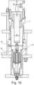
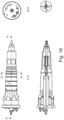
- the injector valve is supplied with liquid gas of a pressure of 8 bar from the fuel rail to ports 24a of the injector valve, fig. 22 (there are four ports 24a). Liquid gas flows through channels 24, fig. 18 , and a suction valve fig. 15 to a chamber 48 in the injector valve, fig. 11 .
- Control oil is supplied to a port 27a, fig 22 .
- Purge oil (hydraulic mineral oil) is supplied to a port 46a, fig. 22 .
- Sealing oil (hydraulic mineral oil) is supplied to a port 47a from where it flows through a channel 12a, fig. 19 , and enters a chamber 51 surrounding a piston 7, fig.
- Sealing oil is applied with a pressure of 150-200 bar when the engine is working.
- Leak oil is coming out from a port 28a, fig. 22 .
- Purge oil is supplied to the port 46a, fig. 22 , from where it flows through a channel 25, fig. 20 , to the suction valve, fig. 15 .
- the injector valve works in the following way:
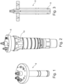
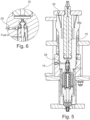
- the injector valve 1 is placed in a holder 2 shown in fig. 14 .
- the injector valve 1 is pressed down by means of a plate 3 which is tightened by means of two nuts 4.
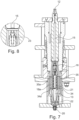
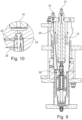
- the injector valve has a port 11, fig. 4 , to which sealing oil is applied, and a port 12 to which control oil is applied. It also has a port 14, fig.5 , to which fuel inlet oil is supplied, and a port 19, fig. 9 , to which purge oil is supplied. It also has a port 28, fig. 11 , which through a leak hose is connected to a spray chamber 29, fig. 14 , and a port 33, fig.5 , connected to the spray chamber 29 through a leak hose.
- a mineral hydraulic oil with a viscosity of 10 cSt is used for the test.
- the test system illustrated in fig. 24 comprises an air driven pump 219 which is able to provide a hydraulic oil pressure of up to 1000 bar of oil from a tank 240.
- the pump 219 is controlled by means of an air pressure regulator 202 which is manually operated.
- the pump 219 is also operated by a pneumatic directional valve 213.
- the hydraulic pressure is displayed at a digital instrument 216.
- the digital instrument receives an electrical signal of 4-20 mA from a pressure transmitter (converter).
- the digital instrument 216 can be set to different modes by means of a selector 230.
- the digital instrument 216 receives an electrical signal from the pressure transmitter and operates the directional valve 203 in response to the signal.
- the digital instrument 216 opens or closes the pneumatic directional valve 213 in response to the mode set by the selector 230.
- the oil pressure from the pump 219 can be released by means of a relief valve 201, in which case the released hydraulic oil will flow back to the tank 240.
- the pump 219 also sucks hydraulic oil from the tank 240 and produces a hydraulic oil pressure which is used as control oil for a fuel injector valve.
- At the outlet pipe line of the pump 219 are mounted manually operated on/off valves 224,222. By opening or closing of the on/off valve 224 a hydraulic accumulator 225 can be charged.
- a safety valve is adjusted to a max pressure of the hydraulic accumulator 225.
- the test system also comprises a second air driven pump 218.
- This pump also sucks also sucks hydraulic oil from the tank 240 and is controlled by means of an air pressure regulator 204.
- the regulator 204 By adjusting the regulator 204 the hydraulic oil pressure from the pump 218 can be adjusted to specific values.
- a pressure gauge 214 shows the hydraulic oil pressure from the pump 218.
- the oil pressure from the pump 218 can be released by means of a relief valve 203.
- a pressure regulator makes it possible to adjust the max oil pressure from the pump 218.
- the oil under pressure from the pump 218 is used as sealing oil, fuel inlet and purge oil which are applied to different sections illustrated in fig. 24 .
- the hydraulic directional valve 210 has two positions. In the first position oil can flow from the fuel injector valve to the tank 241 and in the second position hydraulic oil can flow from the pump 218 to the injector valve. At the fuel inlet section hydraulic oil can flow from the pump 218 through a pressure reduction valve 227, a hydraulic reduction valve 209 and a stop valve 208 to the fuel injector valve, the fuel inlet pressure being shown at a pressure gauge 206.
- the hydraulic directional valve has two positions. In the first position oil can flow from the fuel injector valve to the tank 241.
- hydraulic oil can flow from the pump 218 to the fuel injector valve.
- the stop valve 208 By closing the stop valve 208, if the fuel inlet pressure at the fuel injector valve is increasing, it is possible to see the pressure at the pressure gauge 206.
- hydraulic oil will flow from the pump 218 through a hydraulic directional valve 211 to the fuel injector valve, the purge oil pressure being shown at a pressure gauge.
- the directional valve 211 has two positions. In the first position oil can flow from the fuel injector valve to the tank 241 and in the second position hydraulic oil can flow from the pump 218 to the fuel injector valve.
- the reduction valves 226,227 the hydraulic pressure from the pump 218 can have three different values.
- the test system has two tanks 240,241.
- the first tank 240 is filled with mineral hydraulic oil.
- the second tank 241 contains hydraulic oil collected from the fuel injector valve.
- the hydraulic oil in the tank 241 can include methanol from the fuel injector valve.
- the injector valve 1 When the injector valve 1 is dismounted from the engine, it has to be placed in a cleaning device, fig 23 , as it may contain methanol, f. inst. in the chamber 48, the channels 18,18a and in the nozzle 20. Methanol left in the injector valve 1 has to be flushed out before it can be tested.
- the cleaning system illustrated in fig. 23 is built as a movable unit with four wheels. It consists of a tank 100 and a hydraulic system.
- the tank 100 includes two valve holders. By means of the cleaning system it is possible to transport two fuel injector valves safely at the same time.
- a fuel injector valve which has been dismounted from the cylinder head of an engine may contain some methanol. By placing the injector valve in one of the valve holders it can be transported safely to a workshop.
- the cleaning system comprises an air driven hydraulic pump 104, which is controlled by means of an air pressure regulator.
- the pump 104 sucks flushing liquid from the tank through a filter 105.
- the pressure of the flushing liquid from the pump 104 is shown at a pressure gauge.
- the pressure of the flushing liquid from the pump can be released by means of a relief valve.
- a safety valve 107 At the outlet of the pump 104 is located a safety valve 107.
- the tank 100 is filled with flushing liquid which is a mixture of 95% water and 5% lubrication additives. Methanol can be dissolved in the water.
- the fuel injector valve can be flushed from methanol (which could be left in the fuel injector valve). By a few injections from the fuel injector valve the methanol remaining in the fuel injector valve will be flushed out. During the flushing process the flushing liquid from the pump is applied to the fuel injector valve from the cleaning system.
- the cleaning process is performed as follows
Landscapes
- Engineering & Computer Science (AREA)
- Chemical & Material Sciences (AREA)
- Combustion & Propulsion (AREA)
- Mechanical Engineering (AREA)
- General Engineering & Computer Science (AREA)
- Oil, Petroleum & Natural Gas (AREA)
- Botany (AREA)
- Biotechnology (AREA)
- Biodiversity & Conservation Biology (AREA)
- Sustainable Development (AREA)
- Sustainable Energy (AREA)
- Life Sciences & Earth Sciences (AREA)
- Fuel-Injection Apparatus (AREA)
- Physics & Mathematics (AREA)
- Fluid Mechanics (AREA)
- Examining Or Testing Airtightness (AREA)
- Testing Of Engines (AREA)
Claims (3)
- Procédé destiné à tester une pression d'ouverture d'une soupape d'injection de carburant (1) pour un moteur à combustion, ladite soupape d'injection (1) comportant un couvercle de soupape (5) avec des pistons (6, 7), un orifice d'entrée de fioul (14) pour l'alimentation de fioul via une soupape d'aspiration contenant un piston (16) et un ressort (17), et une buse (20) destinée à injecter du gaz dans un moteur à combustion, dans lequella soupape d'injection avec le couvercle de soupape (5) et les pistons (6, 7) est placée dans un support (2),le couvercle de soupape (5) avec les pistons (6, 7) est retiré et remplacé par une pièce de raccordement (8) avec une bague d'étanchéité (9), ladite pièce de raccordement (8) comportant un orifice d'alimentation en huile d'étanchéité (11) et un orifice d'alimentation en huile de commande (12), ledit orifice d'alimentation en huile de commande communiquant avec un canal (15) ; et dans lequel un système de test est conçu pour alimenter de l'huile d'étanchéité, du fioul et de l'huile de commande vers la soupape d'injection (1), ledit système de test comprenant :une première pompe pneumatique (219) commandée par un premier régulateur de pression pneumatique (202) pour produire une pression d'huile hydraulique destinée à être utilisée pour l'alimentation en huile de commande via une soupape marche/arrêt (222), avec une première soupape de détente (201) conçue pour relâcher la pression d'huile de la première pompe (219), et la pression hydraulique de la pompe (219) étant affichée sur un instrument numérique (216), lequel peut être réglé sur différents modes d'affichage au moyen d'un sélecteur (230) ; etune deuxième pompe pneumatique (218) commandée par un deuxième régulateur de pression pneumatique (204) pour produire une pression d'huile hydraulique destinée à être utilisée pour l'alimentation en huile d'étanchéité via une première soupape de réduction de pression (226) et une première soupape de direction hydraulique (210) et destinée à être utilisée pour l'alimentation en fioul via une deuxième soupape de réduction de pression (227) et d'une deuxième soupape de direction hydraulique (209), avec une deuxième soupape de détente (203) conçue pour relâcher la pression d'huile de la deuxième pompe (218) ;ledit procédé de test comprenant :le réglage du sélecteur (230) sur une position de « pression ouverte » pour amener l'instrument d'affichage (216) à indiquer la pression d'huile de la première pompe (219) ;la fermeture de la deuxième soupape de détente (203) ;l'augmentation de la pression d'huile hydraulique de la deuxième pompe (218) à un maximum de 300 bar au moyen du deuxième régulateur de pression (204), et la commutation de la première soupape de direction (210) vers une position « marche », alimentant ainsi de l'huile d'étanchéité à une pression maximale vers l'orifice d'alimentation en huile d'étanchéité (11), ladite huile d'étanchéité s'écoulant à travers un orifice (12a) vers une aiguille (13) de la soupape d'injection (1) ;la fermeture de la première soupape de détente (201) ;la commutation de la deuxième soupape de direction hydraulique (209) vers une position « marche », et l'application de fioul à une pression de 8 bar au niveau de l'orifice d'entrée de fioul (14), moyennant quoi le fioul à une pression de 8 bar ouvre la soupape d'aspiration en relevant le piston (16) par rapport au ressort (17), et le fioul s'écoule à travers la soupape d'aspiration vers le canal (15) de la pièce de raccordement (8) ;l'ouverture de la soupape marche/arrêt (222) pour alimenter de l'huile de commande vers l'orifice d'huile de commande (12), à travers le canal (15) et à travers des canaux (18, 18a) de la soupape d'injection jusqu'à l'aiguille (13) ;l'augmentation de la pression de l'huile de commande au moyen du premier régulateur de pression (202) jusqu'à ce qu'une pression d'ouverture de la soupape d'injection (1) soit atteinte et que la soupape d'injection pulvérise de l'huile de commande à partir de la buse (20) dans une chambre de pulvérisation (29) ;la détermination de la pression d'ouverture atteinte à partir de l'instrument d'affichage de pression d'huile (216) ;la commutation de la deuxième soupape de direction hydraulique (209) vers une position « arrêt » pour stopper l'alimentation de la soupape d'injection (1) en fioul ;la commutation de la première soupape de direction hydraulique (210) vers une position « arrêt » pour stopper l'alimentation de la soupape d'injection (1) en huile d'étanchéité ; etl'ouverture du premier régulateur de pression (202) et de la première soupape de détente (201) pour relâcher la pression de l'huile de commande alimentée vers la soupape d'injection (1).
- Procédé selon la revendication 1, caractérisé en ce que la pression de l'huile de commande est augmentée à environ 20 bar en dessous de la pression d'ouverture de manière à vérifier si de l'huile s'échappe de la buse (20) de la soupape d'injection.
- Procédé selon la revendication 1, caractérisé en ce qu'une soupape d'arrêt (208) dans l'entrée de fioul vers l'orifice d'alimentation en fioul (14) est fermée, et la pression de fioul est vérifiée (au niveau de 206) sachant que celle-ci devrait être à zéro, sauf en cas de fuite d'huile de commande.
Priority Applications (2)
| Application Number | Priority Date | Filing Date | Title |
|---|---|---|---|
| EP21176302.4A EP3910191B1 (fr) | 2015-03-27 | 2016-03-29 | Procédé permettant de vérifier une soupape de désaération pour une soupape d'injecteur |
| DK21176302.4T DK3910191T3 (da) | 2015-03-27 | 2016-03-29 | Fremgangsmåde til kontrol af en afluftningsventil til en indsprøjtningsventil |
Applications Claiming Priority (2)
| Application Number | Priority Date | Filing Date | Title |
|---|---|---|---|
| DKPA201500193A DK178894B1 (en) | 2015-03-27 | 2015-03-27 | PROCEDURE FOR CHECKING A FLUID GAS INJECTION VALVE |
| PCT/DK2016/050092 WO2016155746A1 (fr) | 2015-03-27 | 2016-03-29 | Procédé pour tester une soupape d'injecteur pour un gaz liquide |
Related Child Applications (2)
| Application Number | Title | Priority Date | Filing Date |
|---|---|---|---|
| EP21176302.4A Division EP3910191B1 (fr) | 2015-03-27 | 2016-03-29 | Procédé permettant de vérifier une soupape de désaération pour une soupape d'injecteur |
| EP21176302.4A Division-Into EP3910191B1 (fr) | 2015-03-27 | 2016-03-29 | Procédé permettant de vérifier une soupape de désaération pour une soupape d'injecteur |
Publications (3)
| Publication Number | Publication Date |
|---|---|
| EP3295016A1 EP3295016A1 (fr) | 2018-03-21 |
| EP3295016A4 EP3295016A4 (fr) | 2020-12-16 |
| EP3295016B1 true EP3295016B1 (fr) | 2024-03-06 |
Family
ID=56998781
Family Applications (2)
| Application Number | Title | Priority Date | Filing Date |
|---|---|---|---|
| EP16771434.4A Active EP3295016B1 (fr) | 2015-03-27 | 2016-03-29 | Procédé pour tester une soupape d'injecteur pour un gaz liquide |
| EP21176302.4A Active EP3910191B1 (fr) | 2015-03-27 | 2016-03-29 | Procédé permettant de vérifier une soupape de désaération pour une soupape d'injecteur |
Family Applications After (1)
| Application Number | Title | Priority Date | Filing Date |
|---|---|---|---|
| EP21176302.4A Active EP3910191B1 (fr) | 2015-03-27 | 2016-03-29 | Procédé permettant de vérifier une soupape de désaération pour une soupape d'injecteur |
Country Status (6)
| Country | Link |
|---|---|
| EP (2) | EP3295016B1 (fr) |
| JP (1) | JP6807861B2 (fr) |
| KR (2) | KR102502851B1 (fr) |
| CN (1) | CN107429653B (fr) |
| DK (4) | DK178894B1 (fr) |
| WO (1) | WO2016155746A1 (fr) |
Families Citing this family (7)
| Publication number | Priority date | Publication date | Assignee | Title |
|---|---|---|---|---|
| CN107270323B (zh) * | 2017-05-18 | 2019-07-05 | 昆明理工大学 | 一种生物质燃油富氧/全氧混沌燃烧实时诊断系统及方法 |
| KR101890316B1 (ko) * | 2017-11-28 | 2018-08-21 | 주식회사 유연이앤이 | 연료분사밸브 시험 장치 및 시험 방법 |
| DK180473B1 (en) * | 2019-09-06 | 2021-05-07 | Iop Marine As | Method for testing a valve body of an injector valve and method for testing an injector valve |
| CN112484074B (zh) * | 2020-11-23 | 2025-01-28 | 沪东重机有限公司 | 一种船用lgip主机燃气分配块 |
| DK181283B1 (en) * | 2021-11-16 | 2023-06-21 | Iop Marine As | Method for testing an injector valve |
| CN116242548A (zh) * | 2023-03-24 | 2023-06-09 | 上海乐春重工机电设备有限公司 | 一种喷气阀件密封测试装置和测试方法 |
| CN116857100B (zh) * | 2023-08-01 | 2026-04-07 | 重庆红江机械有限责任公司 | 一种适用于易气化燃料喷射装置的试验设备 |
Family Cites Families (10)
| Publication number | Priority date | Publication date | Assignee | Title |
|---|---|---|---|---|
| US4041778A (en) * | 1976-09-08 | 1977-08-16 | Fuji Shoten Co. Ltd. | Fuel injection valve testing apparatus |
| DE3825832A1 (de) * | 1988-07-29 | 1990-02-01 | Bosch Gmbh Robert | Verfahren zur ueberpruefung des zweiten oeffnungsdruckes einer zweifeder-duesenhalterkombination |
| JP2753613B2 (ja) * | 1988-12-28 | 1998-05-20 | トヨタ自動車株式会社 | 微粉子分布状態測定方法 |
| US6557402B1 (en) * | 1998-12-18 | 2003-05-06 | Siemens Automotive Corporation | Porous metal flow master |
| KR200384456Y1 (ko) * | 2005-02-18 | 2005-05-16 | 전영근 | 디젤 엔진의 연료분사밸브의 테스트장치 |
| DE102006016443A1 (de) * | 2006-04-07 | 2007-10-11 | Robert Bosch Gmbh | Verfahren zur Leckageprüfung eines ein Magnetventil aufweisenden Kraftstoffinjektors |
| US9038601B2 (en) | 2011-11-01 | 2015-05-26 | Cummins Inc. | Flow limiter assembly for a fuel system of an internal combustion engine |
| DK177454B1 (da) * | 2011-11-09 | 2013-06-17 | Iop Marine As | Fremgangsmåde til afprøvning af en gasinjektionsventil samt et anlæg til udøvelse af fremgangsmåden |
| DK177530B1 (da) | 2012-02-22 | 2013-09-08 | Iop Marine As | Fremgangsmåde til afprøvning af en gas shut-down ventil samt et anlæg til udøvelse af fremgangsmåden |
| KR101352576B1 (ko) * | 2013-09-10 | 2014-01-16 | 유웅자 | 선박 엔진용 연료 분사 밸브의 테스트 장치 |
-
2015
- 2015-03-27 DK DKPA201500193A patent/DK178894B1/en active
-
2016
- 2016-01-26 DK DKPA201600049A patent/DK178641B1/en active
- 2016-03-29 DK DK21176302.4T patent/DK3910191T3/da active
- 2016-03-29 DK DK16771434.4T patent/DK3295016T3/da active
- 2016-03-29 WO PCT/DK2016/050092 patent/WO2016155746A1/fr not_active Ceased
- 2016-03-29 KR KR1020227039763A patent/KR102502851B1/ko active Active
- 2016-03-29 EP EP16771434.4A patent/EP3295016B1/fr active Active
- 2016-03-29 CN CN201680018086.8A patent/CN107429653B/zh active Active
- 2016-03-29 KR KR1020177029204A patent/KR102468205B1/ko active Active
- 2016-03-29 EP EP21176302.4A patent/EP3910191B1/fr active Active
- 2016-03-29 JP JP2017550618A patent/JP6807861B2/ja active Active
Also Published As
| Publication number | Publication date |
|---|---|
| KR102468205B1 (ko) | 2022-11-16 |
| DK201600049A1 (en) | 2016-10-03 |
| EP3295016A4 (fr) | 2020-12-16 |
| EP3910191B1 (fr) | 2023-09-27 |
| JP2018513303A (ja) | 2018-05-24 |
| DK201500193A1 (en) | 2016-10-03 |
| DK3295016T3 (da) | 2024-05-21 |
| EP3910191A1 (fr) | 2021-11-17 |
| EP3295016A1 (fr) | 2018-03-21 |
| KR20170131493A (ko) | 2017-11-29 |
| JP6807861B2 (ja) | 2021-01-06 |
| DK178641B1 (en) | 2016-10-03 |
| KR20220156980A (ko) | 2022-11-28 |
| DK3910191T3 (da) | 2023-11-20 |
| CN107429653A (zh) | 2017-12-01 |
| DK178894B1 (en) | 2017-05-08 |
| WO2016155746A1 (fr) | 2016-10-06 |
| KR102502851B1 (ko) | 2023-02-23 |
| CN107429653B (zh) | 2021-01-05 |
Similar Documents
| Publication | Publication Date | Title |
|---|---|---|
| EP3295016B1 (fr) | Procédé pour tester une soupape d'injecteur pour un gaz liquide | |
| EP2776703B1 (fr) | PROCÉDÉ D'ESSAI D'UNE SOUPAPE D'INJECTION DE GAZ ET SYSTÈME pour réaliser le PROCÉDÉ | |
| KR102927959B1 (ko) | 유입-유출 밸브를 시험하기 위한 시험 유닛 및 방법 | |
| JP7771398B2 (ja) | 噴射弁をテストする方法 | |
| KR102852276B1 (ko) | 인젝터 밸브의 밸브 몸체를 시험하기 위한 방법 및 인젝터 밸브를 시험하기 위한 방법 | |
| DK180461B1 (en) | Method for testing a valve body of an injector valve and method for testing an injector valve | |
| RU2635429C1 (ru) | Топливная система двигателя | |
| WO2005057005A2 (fr) | Systeme permettant de determiner une quantite ejectee d'un dispositif d'injection pour moteurs a combustion interne | |
| JPS6254720B2 (fr) |
Legal Events
| Date | Code | Title | Description |
|---|---|---|---|
| STAA | Information on the status of an ep patent application or granted ep patent |
Free format text: STATUS: THE INTERNATIONAL PUBLICATION HAS BEEN MADE |
|
| PUAI | Public reference made under article 153(3) epc to a published international application that has entered the european phase |
Free format text: ORIGINAL CODE: 0009012 |
|
| STAA | Information on the status of an ep patent application or granted ep patent |
Free format text: STATUS: REQUEST FOR EXAMINATION WAS MADE |
|
| 17P | Request for examination filed |
Effective date: 20171102 |
|
| AK | Designated contracting states |
Kind code of ref document: A1 Designated state(s): AL AT BE BG CH CY CZ DE DK EE ES FI FR GB GR HR HU IE IS IT LI LT LU LV MC MK MT NL NO PL PT RO RS SE SI SK SM TR |
|
| AX | Request for extension of the european patent |
Extension state: BA ME |
|
| DAV | Request for validation of the european patent (deleted) | ||
| DAX | Request for extension of the european patent (deleted) | ||
| RIC1 | Information provided on ipc code assigned before grant |
Ipc: F02D 19/06 20060101ALI20190117BHEP Ipc: F02M 65/00 20060101AFI20190117BHEP |
|
| A4 | Supplementary search report drawn up and despatched |
Effective date: 20201117 |
|
| RIC1 | Information provided on ipc code assigned before grant |
Ipc: F02D 19/06 20060101ALI20201110BHEP Ipc: F02M 65/00 20060101AFI20201110BHEP Ipc: F02M 47/02 20060101ALI20201110BHEP |
|
| STAA | Information on the status of an ep patent application or granted ep patent |
Free format text: STATUS: EXAMINATION IS IN PROGRESS |
|
| 17Q | First examination report despatched |
Effective date: 20220103 |
|
| GRAP | Despatch of communication of intention to grant a patent |
Free format text: ORIGINAL CODE: EPIDOSNIGR1 |
|
| STAA | Information on the status of an ep patent application or granted ep patent |
Free format text: STATUS: GRANT OF PATENT IS INTENDED |
|
| INTG | Intention to grant announced |
Effective date: 20230623 |
|
| GRAJ | Information related to disapproval of communication of intention to grant by the applicant or resumption of examination proceedings by the epo deleted |
Free format text: ORIGINAL CODE: EPIDOSDIGR1 |
|
| STAA | Information on the status of an ep patent application or granted ep patent |
Free format text: STATUS: EXAMINATION IS IN PROGRESS |
|
| GRAJ | Information related to disapproval of communication of intention to grant by the applicant or resumption of examination proceedings by the epo deleted |
Free format text: ORIGINAL CODE: EPIDOSDIGR1 |
|
| GRAP | Despatch of communication of intention to grant a patent |
Free format text: ORIGINAL CODE: EPIDOSNIGR1 |
|
| GRAP | Despatch of communication of intention to grant a patent |
Free format text: ORIGINAL CODE: EPIDOSNIGR1 |
|
| STAA | Information on the status of an ep patent application or granted ep patent |
Free format text: STATUS: GRANT OF PATENT IS INTENDED |
|
| INTC | Intention to grant announced (deleted) | ||
| INTG | Intention to grant announced |
Effective date: 20231024 |
|
| INTG | Intention to grant announced |
Effective date: 20231103 |
|
| GRAS | Grant fee paid |
Free format text: ORIGINAL CODE: EPIDOSNIGR3 |
|
| GRAA | (expected) grant |
Free format text: ORIGINAL CODE: 0009210 |
|
| STAA | Information on the status of an ep patent application or granted ep patent |
Free format text: STATUS: THE PATENT HAS BEEN GRANTED |
|
| AK | Designated contracting states |
Kind code of ref document: B1 Designated state(s): AL AT BE BG CH CY CZ DE DK EE ES FI FR GB GR HR HU IE IS IT LI LT LU LV MC MK MT NL NO PL PT RO RS SE SI SK SM TR |
|
| REG | Reference to a national code |
Ref country code: GB Ref legal event code: FG4D |
|
| REG | Reference to a national code |
Ref country code: CH Ref legal event code: EP |
|
| REG | Reference to a national code |
Ref country code: IE Ref legal event code: FG4D |
|
| REG | Reference to a national code |
Ref country code: DE Ref legal event code: R096 Ref document number: 602016086163 Country of ref document: DE |
|
| REG | Reference to a national code |
Ref country code: DK Ref legal event code: T3 Effective date: 20240514 |
|
| REG | Reference to a national code |
Ref country code: LT Ref legal event code: MG9D |
|
| PG25 | Lapsed in a contracting state [announced via postgrant information from national office to epo] |
Ref country code: LT Free format text: LAPSE BECAUSE OF FAILURE TO SUBMIT A TRANSLATION OF THE DESCRIPTION OR TO PAY THE FEE WITHIN THE PRESCRIBED TIME-LIMIT Effective date: 20240306 |
|
| REG | Reference to a national code |
Ref country code: NL Ref legal event code: MP Effective date: 20240306 |
|
| PG25 | Lapsed in a contracting state [announced via postgrant information from national office to epo] |
Ref country code: GR Free format text: LAPSE BECAUSE OF FAILURE TO SUBMIT A TRANSLATION OF THE DESCRIPTION OR TO PAY THE FEE WITHIN THE PRESCRIBED TIME-LIMIT Effective date: 20240607 |
|
| PG25 | Lapsed in a contracting state [announced via postgrant information from national office to epo] |
Ref country code: RS Free format text: LAPSE BECAUSE OF FAILURE TO SUBMIT A TRANSLATION OF THE DESCRIPTION OR TO PAY THE FEE WITHIN THE PRESCRIBED TIME-LIMIT Effective date: 20240606 Ref country code: HR Free format text: LAPSE BECAUSE OF FAILURE TO SUBMIT A TRANSLATION OF THE DESCRIPTION OR TO PAY THE FEE WITHIN THE PRESCRIBED TIME-LIMIT Effective date: 20240306 |
|
| PG25 | Lapsed in a contracting state [announced via postgrant information from national office to epo] |
Ref country code: ES Free format text: LAPSE BECAUSE OF FAILURE TO SUBMIT A TRANSLATION OF THE DESCRIPTION OR TO PAY THE FEE WITHIN THE PRESCRIBED TIME-LIMIT Effective date: 20240306 |
|
| PG25 | Lapsed in a contracting state [announced via postgrant information from national office to epo] |
Ref country code: RS Free format text: LAPSE BECAUSE OF FAILURE TO SUBMIT A TRANSLATION OF THE DESCRIPTION OR TO PAY THE FEE WITHIN THE PRESCRIBED TIME-LIMIT Effective date: 20240606 Ref country code: NO Free format text: LAPSE BECAUSE OF FAILURE TO SUBMIT A TRANSLATION OF THE DESCRIPTION OR TO PAY THE FEE WITHIN THE PRESCRIBED TIME-LIMIT Effective date: 20240606 Ref country code: LT Free format text: LAPSE BECAUSE OF FAILURE TO SUBMIT A TRANSLATION OF THE DESCRIPTION OR TO PAY THE FEE WITHIN THE PRESCRIBED TIME-LIMIT Effective date: 20240306 Ref country code: HR Free format text: LAPSE BECAUSE OF FAILURE TO SUBMIT A TRANSLATION OF THE DESCRIPTION OR TO PAY THE FEE WITHIN THE PRESCRIBED TIME-LIMIT Effective date: 20240306 Ref country code: GR Free format text: LAPSE BECAUSE OF FAILURE TO SUBMIT A TRANSLATION OF THE DESCRIPTION OR TO PAY THE FEE WITHIN THE PRESCRIBED TIME-LIMIT Effective date: 20240607 Ref country code: FI Free format text: LAPSE BECAUSE OF FAILURE TO SUBMIT A TRANSLATION OF THE DESCRIPTION OR TO PAY THE FEE WITHIN THE PRESCRIBED TIME-LIMIT Effective date: 20240306 Ref country code: ES Free format text: LAPSE BECAUSE OF FAILURE TO SUBMIT A TRANSLATION OF THE DESCRIPTION OR TO PAY THE FEE WITHIN THE PRESCRIBED TIME-LIMIT Effective date: 20240306 Ref country code: BG Free format text: LAPSE BECAUSE OF FAILURE TO SUBMIT A TRANSLATION OF THE DESCRIPTION OR TO PAY THE FEE WITHIN THE PRESCRIBED TIME-LIMIT Effective date: 20240306 |
|
| REG | Reference to a national code |
Ref country code: AT Ref legal event code: MK05 Ref document number: 1663740 Country of ref document: AT Kind code of ref document: T Effective date: 20240306 |
|
| PG25 | Lapsed in a contracting state [announced via postgrant information from national office to epo] |
Ref country code: SE Free format text: LAPSE BECAUSE OF FAILURE TO SUBMIT A TRANSLATION OF THE DESCRIPTION OR TO PAY THE FEE WITHIN THE PRESCRIBED TIME-LIMIT Effective date: 20240306 Ref country code: LV Free format text: LAPSE BECAUSE OF FAILURE TO SUBMIT A TRANSLATION OF THE DESCRIPTION OR TO PAY THE FEE WITHIN THE PRESCRIBED TIME-LIMIT Effective date: 20240306 |
|
| PG25 | Lapsed in a contracting state [announced via postgrant information from national office to epo] |
Ref country code: NL Free format text: LAPSE BECAUSE OF FAILURE TO SUBMIT A TRANSLATION OF THE DESCRIPTION OR TO PAY THE FEE WITHIN THE PRESCRIBED TIME-LIMIT Effective date: 20240306 |
|
| PG25 | Lapsed in a contracting state [announced via postgrant information from national office to epo] |
Ref country code: NL Free format text: LAPSE BECAUSE OF FAILURE TO SUBMIT A TRANSLATION OF THE DESCRIPTION OR TO PAY THE FEE WITHIN THE PRESCRIBED TIME-LIMIT Effective date: 20240306 |
|
| PG25 | Lapsed in a contracting state [announced via postgrant information from national office to epo] |
Ref country code: IS Free format text: LAPSE BECAUSE OF FAILURE TO SUBMIT A TRANSLATION OF THE DESCRIPTION OR TO PAY THE FEE WITHIN THE PRESCRIBED TIME-LIMIT Effective date: 20240706 |
|
| PG25 | Lapsed in a contracting state [announced via postgrant information from national office to epo] |
Ref country code: SM Free format text: LAPSE BECAUSE OF FAILURE TO SUBMIT A TRANSLATION OF THE DESCRIPTION OR TO PAY THE FEE WITHIN THE PRESCRIBED TIME-LIMIT Effective date: 20240306 Ref country code: PT Free format text: LAPSE BECAUSE OF FAILURE TO SUBMIT A TRANSLATION OF THE DESCRIPTION OR TO PAY THE FEE WITHIN THE PRESCRIBED TIME-LIMIT Effective date: 20240708 |
|
| PG25 | Lapsed in a contracting state [announced via postgrant information from national office to epo] |
Ref country code: EE Free format text: LAPSE BECAUSE OF FAILURE TO SUBMIT A TRANSLATION OF THE DESCRIPTION OR TO PAY THE FEE WITHIN THE PRESCRIBED TIME-LIMIT Effective date: 20240306 Ref country code: CZ Free format text: LAPSE BECAUSE OF FAILURE TO SUBMIT A TRANSLATION OF THE DESCRIPTION OR TO PAY THE FEE WITHIN THE PRESCRIBED TIME-LIMIT Effective date: 20240306 |
|
| PG25 | Lapsed in a contracting state [announced via postgrant information from national office to epo] |
Ref country code: AT Free format text: LAPSE BECAUSE OF FAILURE TO SUBMIT A TRANSLATION OF THE DESCRIPTION OR TO PAY THE FEE WITHIN THE PRESCRIBED TIME-LIMIT Effective date: 20240306 |
|
| PG25 | Lapsed in a contracting state [announced via postgrant information from national office to epo] |
Ref country code: PL Free format text: LAPSE BECAUSE OF FAILURE TO SUBMIT A TRANSLATION OF THE DESCRIPTION OR TO PAY THE FEE WITHIN THE PRESCRIBED TIME-LIMIT Effective date: 20240306 |
|
| PG25 | Lapsed in a contracting state [announced via postgrant information from national office to epo] |
Ref country code: SK Free format text: LAPSE BECAUSE OF FAILURE TO SUBMIT A TRANSLATION OF THE DESCRIPTION OR TO PAY THE FEE WITHIN THE PRESCRIBED TIME-LIMIT Effective date: 20240306 |
|
| PG25 | Lapsed in a contracting state [announced via postgrant information from national office to epo] |
Ref country code: SM Free format text: LAPSE BECAUSE OF FAILURE TO SUBMIT A TRANSLATION OF THE DESCRIPTION OR TO PAY THE FEE WITHIN THE PRESCRIBED TIME-LIMIT Effective date: 20240306 Ref country code: SK Free format text: LAPSE BECAUSE OF FAILURE TO SUBMIT A TRANSLATION OF THE DESCRIPTION OR TO PAY THE FEE WITHIN THE PRESCRIBED TIME-LIMIT Effective date: 20240306 Ref country code: RO Free format text: LAPSE BECAUSE OF FAILURE TO SUBMIT A TRANSLATION OF THE DESCRIPTION OR TO PAY THE FEE WITHIN THE PRESCRIBED TIME-LIMIT Effective date: 20240306 Ref country code: PT Free format text: LAPSE BECAUSE OF FAILURE TO SUBMIT A TRANSLATION OF THE DESCRIPTION OR TO PAY THE FEE WITHIN THE PRESCRIBED TIME-LIMIT Effective date: 20240708 Ref country code: PL Free format text: LAPSE BECAUSE OF FAILURE TO SUBMIT A TRANSLATION OF THE DESCRIPTION OR TO PAY THE FEE WITHIN THE PRESCRIBED TIME-LIMIT Effective date: 20240306 Ref country code: IS Free format text: LAPSE BECAUSE OF FAILURE TO SUBMIT A TRANSLATION OF THE DESCRIPTION OR TO PAY THE FEE WITHIN THE PRESCRIBED TIME-LIMIT Effective date: 20240706 Ref country code: EE Free format text: LAPSE BECAUSE OF FAILURE TO SUBMIT A TRANSLATION OF THE DESCRIPTION OR TO PAY THE FEE WITHIN THE PRESCRIBED TIME-LIMIT Effective date: 20240306 Ref country code: CZ Free format text: LAPSE BECAUSE OF FAILURE TO SUBMIT A TRANSLATION OF THE DESCRIPTION OR TO PAY THE FEE WITHIN THE PRESCRIBED TIME-LIMIT Effective date: 20240306 Ref country code: AT Free format text: LAPSE BECAUSE OF FAILURE TO SUBMIT A TRANSLATION OF THE DESCRIPTION OR TO PAY THE FEE WITHIN THE PRESCRIBED TIME-LIMIT Effective date: 20240306 |
|
| PG25 | Lapsed in a contracting state [announced via postgrant information from national office to epo] |
Ref country code: LU Free format text: LAPSE BECAUSE OF NON-PAYMENT OF DUE FEES Effective date: 20240329 |
|
| PG25 | Lapsed in a contracting state [announced via postgrant information from national office to epo] |
Ref country code: LU Free format text: LAPSE BECAUSE OF NON-PAYMENT OF DUE FEES Effective date: 20240329 |
|
| PG25 | Lapsed in a contracting state [announced via postgrant information from national office to epo] |
Ref country code: IT Free format text: LAPSE BECAUSE OF FAILURE TO SUBMIT A TRANSLATION OF THE DESCRIPTION OR TO PAY THE FEE WITHIN THE PRESCRIBED TIME-LIMIT Effective date: 20240306 |
|
| REG | Reference to a national code |
Ref country code: DE Ref legal event code: R097 Ref document number: 602016086163 Country of ref document: DE |
|
| REG | Reference to a national code |
Ref country code: BE Ref legal event code: MM Effective date: 20240331 |
|
| PG25 | Lapsed in a contracting state [announced via postgrant information from national office to epo] |
Ref country code: IT Free format text: LAPSE BECAUSE OF FAILURE TO SUBMIT A TRANSLATION OF THE DESCRIPTION OR TO PAY THE FEE WITHIN THE PRESCRIBED TIME-LIMIT Effective date: 20240306 |
|
| PG25 | Lapsed in a contracting state [announced via postgrant information from national office to epo] |
Ref country code: MC Free format text: LAPSE BECAUSE OF FAILURE TO SUBMIT A TRANSLATION OF THE DESCRIPTION OR TO PAY THE FEE WITHIN THE PRESCRIBED TIME-LIMIT Effective date: 20240306 |
|
| PLBE | No opposition filed within time limit |
Free format text: ORIGINAL CODE: 0009261 |
|
| STAA | Information on the status of an ep patent application or granted ep patent |
Free format text: STATUS: NO OPPOSITION FILED WITHIN TIME LIMIT |
|
| PG25 | Lapsed in a contracting state [announced via postgrant information from national office to epo] |
Ref country code: BE Free format text: LAPSE BECAUSE OF NON-PAYMENT OF DUE FEES Effective date: 20240331 |
|
| PG25 | Lapsed in a contracting state [announced via postgrant information from national office to epo] |
Ref country code: IE Free format text: LAPSE BECAUSE OF NON-PAYMENT OF DUE FEES Effective date: 20240329 |
|
| PG25 | Lapsed in a contracting state [announced via postgrant information from national office to epo] |
Ref country code: MC Free format text: LAPSE BECAUSE OF FAILURE TO SUBMIT A TRANSLATION OF THE DESCRIPTION OR TO PAY THE FEE WITHIN THE PRESCRIBED TIME-LIMIT Effective date: 20240306 Ref country code: IE Free format text: LAPSE BECAUSE OF NON-PAYMENT OF DUE FEES Effective date: 20240329 Ref country code: BE Free format text: LAPSE BECAUSE OF NON-PAYMENT OF DUE FEES Effective date: 20240331 |
|
| 26N | No opposition filed |
Effective date: 20241209 |
|
| GBPC | Gb: european patent ceased through non-payment of renewal fee |
Effective date: 20240606 |
|
| PG25 | Lapsed in a contracting state [announced via postgrant information from national office to epo] |
Ref country code: SI Free format text: LAPSE BECAUSE OF FAILURE TO SUBMIT A TRANSLATION OF THE DESCRIPTION OR TO PAY THE FEE WITHIN THE PRESCRIBED TIME-LIMIT Effective date: 20240306 |
|
| PG25 | Lapsed in a contracting state [announced via postgrant information from national office to epo] |
Ref country code: FR Free format text: LAPSE BECAUSE OF NON-PAYMENT OF DUE FEES Effective date: 20240506 |
|
| PG25 | Lapsed in a contracting state [announced via postgrant information from national office to epo] |
Ref country code: GB Free format text: LAPSE BECAUSE OF NON-PAYMENT OF DUE FEES Effective date: 20240606 |
|
| PGFP | Annual fee paid to national office [announced via postgrant information from national office to epo] |
Ref country code: CH Payment date: 20250401 Year of fee payment: 10 |
|
| PG25 | Lapsed in a contracting state [announced via postgrant information from national office to epo] |
Ref country code: CY Free format text: LAPSE BECAUSE OF FAILURE TO SUBMIT A TRANSLATION OF THE DESCRIPTION OR TO PAY THE FEE WITHIN THE PRESCRIBED TIME-LIMIT; INVALID AB INITIO Effective date: 20160329 |
|
| PG25 | Lapsed in a contracting state [announced via postgrant information from national office to epo] |
Ref country code: HU Free format text: LAPSE BECAUSE OF FAILURE TO SUBMIT A TRANSLATION OF THE DESCRIPTION OR TO PAY THE FEE WITHIN THE PRESCRIBED TIME-LIMIT; INVALID AB INITIO Effective date: 20160329 |
|
| PG25 | Lapsed in a contracting state [announced via postgrant information from national office to epo] |
Ref country code: TR Free format text: LAPSE BECAUSE OF FAILURE TO SUBMIT A TRANSLATION OF THE DESCRIPTION OR TO PAY THE FEE WITHIN THE PRESCRIBED TIME-LIMIT Effective date: 20240306 |
|
| REG | Reference to a national code |
Ref country code: CH Ref legal event code: U11 Free format text: ST27 STATUS EVENT CODE: U-0-0-U10-U11 (AS PROVIDED BY THE NATIONAL OFFICE) Effective date: 20260401 |
|
| PGFP | Annual fee paid to national office [announced via postgrant information from national office to epo] |
Ref country code: DE Payment date: 20260304 Year of fee payment: 11 Ref country code: DK Payment date: 20260304 Year of fee payment: 11 |