EP3295033B1 - Dispositif immergé hydrodynamique magnétique pour entraînement à vitesse variable - Google Patents
Dispositif immergé hydrodynamique magnétique pour entraînement à vitesse variable Download PDFInfo
- Publication number
- EP3295033B1 EP3295033B1 EP16777794.5A EP16777794A EP3295033B1 EP 3295033 B1 EP3295033 B1 EP 3295033B1 EP 16777794 A EP16777794 A EP 16777794A EP 3295033 B1 EP3295033 B1 EP 3295033B1
- Authority
- EP
- European Patent Office
- Prior art keywords
- booster unit
- magnetic coupling
- fluid
- coupling
- shaft
- Prior art date
- Legal status (The legal status is an assumption and is not a legal conclusion. Google has not performed a legal analysis and makes no representation as to the accuracy of the status listed.)
- Active
Links
Images

Classifications
-
- F—MECHANICAL ENGINEERING; LIGHTING; HEATING; WEAPONS; BLASTING
- F04—POSITIVE - DISPLACEMENT MACHINES FOR LIQUIDS; PUMPS FOR LIQUIDS OR ELASTIC FLUIDS
- F04D—NON-POSITIVE-DISPLACEMENT PUMPS
- F04D25/00—Pumping installations or systems
- F04D25/02—Units comprising pumps and their driving means
- F04D25/06—Units comprising pumps and their driving means the pump being electrically driven
- F04D25/0686—Units comprising pumps and their driving means the pump being electrically driven specially adapted for submerged use
-
- E—FIXED CONSTRUCTIONS
- E21—EARTH OR ROCK DRILLING; MINING
- E21B—EARTH OR ROCK DRILLING; OBTAINING OIL, GAS, WATER, SOLUBLE OR MELTABLE MATERIALS OR A SLURRY OF MINERALS FROM WELLS
- E21B43/00—Methods or apparatus for obtaining oil, gas, water, soluble or meltable materials or a slurry of minerals from wells
- E21B43/12—Methods or apparatus for controlling the flow of the obtained fluid to or in wells
- E21B43/121—Lifting well fluids
- E21B43/128—Adaptation of pump systems with down-hole electric drives
-
- F—MECHANICAL ENGINEERING; LIGHTING; HEATING; WEAPONS; BLASTING
- F04—POSITIVE - DISPLACEMENT MACHINES FOR LIQUIDS; PUMPS FOR LIQUIDS OR ELASTIC FLUIDS
- F04D—NON-POSITIVE-DISPLACEMENT PUMPS
- F04D13/00—Pumping installations or systems
- F04D13/02—Units comprising pumps and their driving means
- F04D13/021—Units comprising pumps and their driving means containing a coupling
- F04D13/022—Units comprising pumps and their driving means containing a coupling a coupling allowing slip, e.g. torque converter
-
- F—MECHANICAL ENGINEERING; LIGHTING; HEATING; WEAPONS; BLASTING
- F04—POSITIVE - DISPLACEMENT MACHINES FOR LIQUIDS; PUMPS FOR LIQUIDS OR ELASTIC FLUIDS
- F04D—NON-POSITIVE-DISPLACEMENT PUMPS
- F04D13/00—Pumping installations or systems
- F04D13/02—Units comprising pumps and their driving means
- F04D13/021—Units comprising pumps and their driving means containing a coupling
- F04D13/022—Units comprising pumps and their driving means containing a coupling a coupling allowing slip, e.g. torque converter
- F04D13/023—Units comprising pumps and their driving means containing a coupling a coupling allowing slip, e.g. torque converter for reducing start torque
-
- F—MECHANICAL ENGINEERING; LIGHTING; HEATING; WEAPONS; BLASTING
- F04—POSITIVE - DISPLACEMENT MACHINES FOR LIQUIDS; PUMPS FOR LIQUIDS OR ELASTIC FLUIDS
- F04D—NON-POSITIVE-DISPLACEMENT PUMPS
- F04D13/00—Pumping installations or systems
- F04D13/02—Units comprising pumps and their driving means
- F04D13/021—Units comprising pumps and their driving means containing a coupling
- F04D13/024—Units comprising pumps and their driving means containing a coupling a magnetic coupling
-
- F—MECHANICAL ENGINEERING; LIGHTING; HEATING; WEAPONS; BLASTING
- F04—POSITIVE - DISPLACEMENT MACHINES FOR LIQUIDS; PUMPS FOR LIQUIDS OR ELASTIC FLUIDS
- F04D—NON-POSITIVE-DISPLACEMENT PUMPS
- F04D13/00—Pumping installations or systems
- F04D13/02—Units comprising pumps and their driving means
- F04D13/021—Units comprising pumps and their driving means containing a coupling
- F04D13/024—Units comprising pumps and their driving means containing a coupling a magnetic coupling
- F04D13/025—Details of the can separating the pump and drive area
-
- F—MECHANICAL ENGINEERING; LIGHTING; HEATING; WEAPONS; BLASTING
- F04—POSITIVE - DISPLACEMENT MACHINES FOR LIQUIDS; PUMPS FOR LIQUIDS OR ELASTIC FLUIDS
- F04D—NON-POSITIVE-DISPLACEMENT PUMPS
- F04D13/00—Pumping installations or systems
- F04D13/02—Units comprising pumps and their driving means
- F04D13/021—Units comprising pumps and their driving means containing a coupling
- F04D13/024—Units comprising pumps and their driving means containing a coupling a magnetic coupling
- F04D13/027—Details of the magnetic circuit
-
- F—MECHANICAL ENGINEERING; LIGHTING; HEATING; WEAPONS; BLASTING
- F04—POSITIVE - DISPLACEMENT MACHINES FOR LIQUIDS; PUMPS FOR LIQUIDS OR ELASTIC FLUIDS
- F04D—NON-POSITIVE-DISPLACEMENT PUMPS
- F04D13/00—Pumping installations or systems
- F04D13/02—Units comprising pumps and their driving means
- F04D13/04—Units comprising pumps and their driving means the pump being fluid driven
-
- F—MECHANICAL ENGINEERING; LIGHTING; HEATING; WEAPONS; BLASTING
- F04—POSITIVE - DISPLACEMENT MACHINES FOR LIQUIDS; PUMPS FOR LIQUIDS OR ELASTIC FLUIDS
- F04D—NON-POSITIVE-DISPLACEMENT PUMPS
- F04D13/00—Pumping installations or systems
- F04D13/02—Units comprising pumps and their driving means
- F04D13/06—Units comprising pumps and their driving means the pump being electrically driven
- F04D13/0653—Units comprising pumps and their driving means the pump being electrically driven the motor being flooded
-
- F—MECHANICAL ENGINEERING; LIGHTING; HEATING; WEAPONS; BLASTING
- F04—POSITIVE - DISPLACEMENT MACHINES FOR LIQUIDS; PUMPS FOR LIQUIDS OR ELASTIC FLUIDS
- F04D—NON-POSITIVE-DISPLACEMENT PUMPS
- F04D13/00—Pumping installations or systems
- F04D13/02—Units comprising pumps and their driving means
- F04D13/06—Units comprising pumps and their driving means the pump being electrically driven
- F04D13/08—Units comprising pumps and their driving means the pump being electrically driven for submerged use
- F04D13/086—Units comprising pumps and their driving means the pump being electrically driven for submerged use the pump and drive motor are both submerged
-
- F—MECHANICAL ENGINEERING; LIGHTING; HEATING; WEAPONS; BLASTING
- F04—POSITIVE - DISPLACEMENT MACHINES FOR LIQUIDS; PUMPS FOR LIQUIDS OR ELASTIC FLUIDS
- F04D—NON-POSITIVE-DISPLACEMENT PUMPS
- F04D25/00—Pumping installations or systems
- F04D25/02—Units comprising pumps and their driving means
- F04D25/022—Units comprising pumps and their driving means comprising a yielding coupling, e.g. hydraulic
-
- F—MECHANICAL ENGINEERING; LIGHTING; HEATING; WEAPONS; BLASTING
- F04—POSITIVE - DISPLACEMENT MACHINES FOR LIQUIDS; PUMPS FOR LIQUIDS OR ELASTIC FLUIDS
- F04D—NON-POSITIVE-DISPLACEMENT PUMPS
- F04D25/00—Pumping installations or systems
- F04D25/02—Units comprising pumps and their driving means
- F04D25/026—Units comprising pumps and their driving means with a magnetic coupling
-
- F—MECHANICAL ENGINEERING; LIGHTING; HEATING; WEAPONS; BLASTING
- F04—POSITIVE - DISPLACEMENT MACHINES FOR LIQUIDS; PUMPS FOR LIQUIDS OR ELASTIC FLUIDS
- F04D—NON-POSITIVE-DISPLACEMENT PUMPS
- F04D25/00—Pumping installations or systems
- F04D25/02—Units comprising pumps and their driving means
- F04D25/04—Units comprising pumps and their driving means the pump being fluid-driven
- F04D25/045—Units comprising pumps and their driving means the pump being fluid-driven the pump wheel carrying the fluid driving means, e.g. turbine blades
-
- F—MECHANICAL ENGINEERING; LIGHTING; HEATING; WEAPONS; BLASTING
- F04—POSITIVE - DISPLACEMENT MACHINES FOR LIQUIDS; PUMPS FOR LIQUIDS OR ELASTIC FLUIDS
- F04D—NON-POSITIVE-DISPLACEMENT PUMPS
- F04D29/00—Details, component parts, or accessories
- F04D29/58—Cooling; Heating; Diminishing heat transfer
- F04D29/5806—Cooling the drive system
Definitions
- the present invention relates generally to boosting systems suitable for subsea use, more particulary to motor driven pumps and compressors (pressure booster units), and more particularly to submersible motor driven pumps and compressors having a torque transmitting assembly.
- Subsea production pumps generally fall into the following types:
- Centrifugal Helico-axial (Axial flow). These subsea pumps have been proven for large applications. These pumps are generally very large, have low efficiency and need high shaft speeds (up to 6500 rpm).
- Centrifugal Mixed flow. These pumps have been qualified for subsea applications. They generally provide higher efficiency and need lower shaft speeds (up to 5400 rpm).
- Twin-screw These pumps have on a few occasions been installed for seabed pumping applications and tested in downhole applications. They are generally highly efficient when handling high viscosity fluids, but have historically had low reliability, particularly in the presence of particles.
- Electrical submersible pumps These pumps are mostly of centrifugal type but can also be of positive displacement type and have generally been utilized for downhole applications and work well with high volumes. They have been used for selected injection applications.
- WO 2014/168488 discloses a subsea turbomachine assembly comprising a motor driving a motor shaft and a turbomachine with a turbomachine shaft, an axial bearing and two radial bearings.
- the turbomachine assembly comprises a magnetic lifting assembly comprising a magnetic reaction element coupled to the motor shaft and/or the turbomachine shaft, and a magnetic lifting element coupled to the housing and operatively connectable to the magnetic reaction element. It further comprises a magnetic coupling between the motor shaft and the turbomachine shaft, adapted to transmit rotational movement between them.
- a fluid tight barrier extends through the magnetic coupling and separates the motor shaft from the turbomachine shaft.
- the present invention herein encompass a unique low cost and efficient submersible variable speed drive unit suitable for driving submerged booster units for operating submersed in a body of water and incorporates a permanent magnet coupling and hydraulic coupling system and an integrated variable speed drive functionality.
- the novelty of the concept includes the integration of a unique variable speed torque transmitting pressure barrier system, containing a magnetic coupling design with hydraulic coupling and impeller technology modified to efficiently operate in conjunction with a magnetic coupling for long-term subsea usage in a manner that has not been tried before. Integration of the above torque transmitting coupling system makes it possible to remove all auxiliary systems except the power string and will enable longer step outs than currently possible with existing technology.
- the drive unit described comprises a liquid-filled standard electric motor transmitting torque to a single-phase or multiphase centrifugal pump via a sophisticated combined magnetic and hydraulic coupling system.
- the system incorporates a unique combination of (i) specially designed permanent magnetic coupling system to transfer torque between the main electric motor and the main pump or compressor with an integrated cooling, pressure compensating and lubrication system that also serves as a pressure barrier and (ii) a small pump impeller and a turbine wheel embedded in a hydraulic coupling system to transfer torque between the main electric motor and the main pump or compressor.
- the system also incorporates an actuating system connected to internal guide vanes that control the liquid flow between the small pump and turbine wheels of the coupling and hence the torque and speed.
- the combination of the integrated permanent magnetic coupling and a hydrodynamic coupling serves as a combined pressure barrier and torque converter for the system. This combination serves two main functions.
- the system hermetically separates the pumped process fluid from the cooling and lubricating fluid and surrounding seawater by means of a non-contact magnetic coupling and a static pressure barrier rated to take up towards 1035 bar differential pressure.
- the barrier created by the system removes the need for a mechanical seal and the need for barrier fluid lubrication of the seal.
- the hydraulic torque-coupling serves as a non-contact pump and turbine system that provides variable speed and soft-start functionality as well as complete torque control over the full range of speeds.
- the preferred embodiment described herein results in a unique seal-less and topside-less drive unit that can operate in harsh subsea environments without the need for costly and fragile mechanical shaft seals, complex barrier fluid systems, large topside hydraulic pressure units and variable speed drives.
- the system is particularly beneficial to smaller field developments, niche-pumping applications, sensitive environmental conditions where the potential of leaking seals would be problematic and applications where larger and more complex field development solutions using existing technology are needed or desirable.
- the system described herein is highly flexible and adaptable and capable of being used to drive a submerged booster unit to boost oil and gas, inject or separate water, pump multiphase fluids efficiently and act as a cooler for other subsea applications.
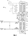
- the system generally referred to as 100, includes a pump or compressor 10, preferably either a single or multistage pump or compressor, driven by a motor 20, typically an electrical motor, via a torque-transmitting assembly 50 comprising a hydrodynamic coupling 30 and a magnetic coupling 40.
- a pump or compressor 10 preferably either a single or multistage pump or compressor, driven by a motor 20, typically an electrical motor, via a torque-transmitting assembly 50 comprising a hydrodynamic coupling 30 and a magnetic coupling 40.
- the motor 20, hydrodynamic coupling 30 and a first portion of the magnetic coupling 40 are contained in a drive unit compartment 21 and a second portion of the magnetic coupling 40 and the pump or compressor 10 are contained in a boosting unit compartment 11.
- the pump or compressor 10 preferably includes a pump hydraulics pump cartridge or a compressor thermodynamics cartridge 18.
- the system 100 includes a variable speed drive functionality in addition to a soft start feature.
- the entire boosting system 100, including all auxiliary systems, are designed for submersible usage (subsea applications).
- the combination of the magnetic coupling 40 with the hydrodynamic coupling 30 provides a unique aspect of the torque-transmitting assembly 50.
- the magnetic coupling 40 is a device capable of transmitting force through space without physical contact by using magnetic forces to perform work in a rotary manner.
- the magnetic coupling 40 includes a driver portion having a magnet 44 mounted to the lower end of the stub shaft 32 and a follower portion having magnet 46 mounted to an upper end of the pump shaft 12.
- the magnetic coupling 40 separates the process side of the pump/compressor 10 from the electrical motor 20 side through the pressure containment shell 42.
- the drive unit compartment 21 with the pressure containment shell 42 comprises a hermetically sealed container around the electrical motor 20, the hydrodynamic coupling 30 and the driver portion of the magnetic coupling 40.
- the pressure containment shell 42 assures a clean cooling and lubricating fluid 4 in the drive unit compartment 21 without any risk of contamination caused by the process fluid 6.
- the magnetic coupling 40 can be of the synchronous or asynchronous type depending on the application. Magnetic couplings 40 are well known to those skilled in the art of seal-less rotodynamic boosting system development. One example of a suitable magnetic coupling is disclosed in applicant's co-pending U.S. Application Serial No. 14/516,079 . This unique magnetic coupling eliminates the need for seals as leak barriers and provides a unique process for sealing the motor assembly, reduces risks of leakage of process fluids and enables the system to operate at extreme water depths without risk of environmental leaks.
- the pump/compressor shaft 12 is driven by magnetic coupling 40 between a follower portion magnet 46, pressure containment shell 42, and driver portion magnet 44 which is rotated via stub shaft 32 by hydrodynamic coupling 30 via rotation of the shaft 22 of the motor 20.
- the torque-transmitting system 50 is mechanically separated.
- the hydrodynamic coupling 30, as well as the driver portion 44 of the magnetic coupling 40, is mechanically separated from the follower portion 46 of the coupling 40, and hence it mechanically separates the pump/compressor 10 from the motor 20. This minimizes the load on bearings and shaft since it will be only the weight of the motor rotor 26 and the hydrodynamic coupling 30 that generates the breakaway torque.
- the required torque generated by the motor 20 is transmitted through electromagnetic forces to the pump/compressor 10.
- the magnetic coupling 40 and the hydrodynamic coupling 30 are connected through a stub shaft 32.
- Each coupling component 30, 40 generates both axial and radial forces. Therefore, to handle the generated forces radial bearings 52M and thrust bearings 54M are mounted onto the stub shaft 32.
- radial bearings 52M and thrust bearings 54M are mounted onto the stub shaft 32.
- at least one radial bearing 52M is mounted on a motor drive shaft 22 located above the stub shaft 32.
- the pump/compressor 10 preferably includes upper and lower radial bearings 52P and a thrust bearing arrangement 54P.
- the hydrodynamic coupling 30 transmits the power generated by the electrical motor 20 via the magnetic coupling 40 to a pump/compressor shaft 12.
- the functionality of the hydrodynamic coupling 30 is based on three main components: an impeller 34, a turbine 36 and several guiding vanes 38 positioned within a housing.
- Hydrodynamic couplings 30 are well known to those skilled in the art of fluid couplings. With reference to Fig. 3 , the impeller 34 has a plurality of impeller vanes 38A and the turbine 36 has a plurality of turbine vanes 38B.
- the impeller 34 and turbine 36 are preferably arranged in facing relationship to one another in the enclosed housing.
- the hydrodynamic coupling 30 provides power transmission based on an indirect operating principle.
- the driven impeller 34 transfers the introduced mechanical energy from the motor 20 to kinetic energy in fluid flow.
- the shape of the impeller vanes 38A forces the fluid flow in the direction of the turbine vanes 38B resulting in a net force causing a torque which causes the turbine 36 to rotate in the same direction as the impeller 34.
- the higher energy fluid flows centrifugally from the driven impeller 34 to the turbine 36 where the reconversion to mechanical energy takes place.
- the power is transferred from the impeller 34 to the turbine 36 without any direct contact.
- the amount of torque transmitted from the motor 20 to the pump/compressor 10 depends on the torque required by the pump/compressor application itself and the losses generated in the magnetic coupling 40.
- the position of the guiding vanes 38 supporting the turbine 36 with energized fluid controls the torque transmitted.
- the hydrodynamic coupling 30 can be operated in three modes: constant speed mode, constant power mode and combined mode.
- constant speed mode the power transmitted by the hydrodynamic coupling 30 is adjusted through internal guide vanes 38 by controlling the fluid 4 to the turbine 36 through an actuator 39.
- the type of actuator may be either electric or hydraulic.
- constant power mode the hydrodynamic coupling 30 is operated with fixed guide vanes 38 and the speed is free to vary based on the required pump torque.
- the combined mode is an optimized mode where the constant speed mode and the constant power mode combine their functionality to meet all possible operating points.
- a unique control system is embedded within the Hydromag coupling system for guide vane positioning.
- This control system includes hardware in the form of an electric or hydraulic actuating mechanism 39 as well as software installed on electric circuitry.
- the objective of the control system is two-fold: (1) protect the pump/compressor unit and (2) ensure ideal performance within the pump/compressor unit duty range.
- the primary objective is to protect the system from being overloaded with excessive torque (single-phase or multiphase applications) or avoid the pump operating close to or beyond the surge line (multiphase applications).
- the control system will require two main inputs: actual pump shaft speed and guide vane position. From mapping this input with databases of pump test data (torque, speed, power, guide vane position), the control system output is a new guide vane position if the pump/compressor is venturing into overloading (excessive torque) or unstable over-speeding (surge/low torque) modes.
- the objective is to ensure that the pump/compressor operates within the targeted duty range (operating envelope) or is even adjusted to meet a certain duty point.
- the control system will have guide vane position and shaft speed as input, compare this with databases of actual test data and provide the ideal guide vane position for the wanted duty area and/or the area that gives the best efficiency or maximum torque (Note: the maximum torque condition in the Hydromag unit occurs at high speed conditions and is dependent on the hydraulic or the thermodynamic selection. The maximum viscous loss condition is when the magnetic losses in the Hydromag unit is at its lowest, which is at maximum speed).
- the first and second objectives essentially mean the same, depending on safety margins.
- the inherent variable speed feature of the hydraulic coupling operating in constant power mode assures for that the operating envelope protection mode always is activated in case the pump/compressor experiences inlet fluid conditions which creates upset conditions.
- the torque-transmitting assembly 50 generates both viscous and electromagnetic losses. To cool off these losses an internal flow network system 24 is used.
- the flow network system 24 also assures sufficient lubrication of the magnetic coupling 40 (if equipped with internal bearings), the hydrodynamic coupling 30, the radial bearings 52M and the axial bearing 54M in the section above the pressure containment shell 42. Additionally, a cooling circulation impeller 28 may be mounted to an upper end of the motor shaft 22.
- the pressure containment shell 42 in the magnetic coupling 40 isolates the process fluid 6 from the cooling and lubricating fluid 4. This assures a 100% clean cooling fluid 4 at all times. By isolating the process fluid, the system is able to operate in sensitive environmental conditions.
- the flow network system 24 filters part of the cooling flow 4 through a filter 74 mounted in parallel to a cooling coil 72. Preferably, a fractional motor cooling flow 4 is continuously filtered.
- the flow network system 24 preferably includes a fluid pressure compensator 76.
- the flow network system 24 includes at least one inlet and at least one outlet with the drive unit compartment 21 to provide circulating cooling fluid 4 to the components contained within the drive unit compartment 21.
- One of the features of the torque-transmitting assembly 50 is the ability to increase the operating speed of the pump/compressor 10 up to two times the motor speed (in the combined control mode).
- a reduction in motor speed reduces significantly the viscous losses generated in the motor 20.
- the viscous motor loss is the main loss contributor to the total losses in flooded motors. More specifically, in multiphase pumping systems, the pump speed frequently needs to be in the 4000-6000 rpm range, which can cause losses higher than 400 kW in 3000 kW systems.
- the viscous losses in the motor are proportional to the motor speed to the power of three (viscous loss motor ⁇ motor speed 3 ). A reduction in motor speed with up to two times will therefore reduce the viscous motor losses with up to eight times.
- the unique combination of the hydrodynamic coupling in series with a magnetic coupling driven by an electrical motor generates an efficient variable speed pump system that is independent of the process pressure and can operate with constant pressure surrounding the components with respect to the ambient sea pressure. This will guarantee 100% control of the internal flow network that lubricates and cools the components themselves since the differential pressure always will be the same over respective component independent of the process pressure.
- the system's combination of a centrifugal pump with the ability to spin faster than the speed of the motor with up to two times due to the hydrodynamic coupling feature allows for a substantial reduction in the power requirements for the system and increased motor efficiencies.
- conventional analysis would not have thought to combine a high rpm motor with a smaller centrifugal pump due to inherent viscous losses that would be expected.
- Another feature is the inherent soft start functionality of the hydrodynamic coupling 30 that makes it possible to operate the pump/compressor 10 with a direct start of the electrical motor 20.
- the ability to have soft start functionality substantially reduces the power requirements of the system and the associated costs of providing increased power. The lower power requirements also enable the system to be economically applied to smaller and more marginal fields.
- the ability to have a soft start is due to the hydrodynamic system behavior of the impeller 34, the turbine 36 and the guide vanes 38 in the hydrodynamic coupling 30. Initially, if the guide vanes 38 are in the closed position there is no torque generated through the turbine 36, only internal recirculation in the impeller 34.
- the actuator 39 gradually opens the guide vanes 38 to the pump parking speed or to the wanted opening position to meet the required pump torque and speed.
- VSD variable speed drive
- the pump/compressor start will be more of the soft start type, due to the inherent time delay of the hydrodynamics in the hydrodynamic coupling 30. That is, it will take some time to build-up a flow in the impeller 34 to drive the torque-generating turbine 36 that will drive the pump/compressor 10 through the magnetic coupling 40.
- the radial and thrust bearings 52P, 54P in the pump section of the system 100 are lubricated by the process fluid 6.
- these radial bearings 52P and thrust bearings 54P cannot be suitably lubricated by the process fluid 6 in cases where the process fluid 6 is very contaminated and in multiphase applications where gas is one of the components in the process fluid 6.
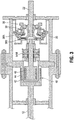
- like reference numbers in Fig. 2 and Fig. 1 refer to the same components and the related discussion with respect to the component in Fig. 1 equally pertains to the like component in Fig. 2 , unless stated otherwise.
- the system 100 includes a pump/compressor 10 driven by a motor 20 via a torque-transmitting assembly 50 comprising a hydrodynamic coupling 30 and a magnetic coupling 40.
- the system 100' includes a variable speed drive functionality in addition to a soft start feature.
- the entire boosting system 100' including all auxiliary systems are designed for submersible usage (subsea applications).
- the system 100' further comprises the following similar elements as in system 100: a pump/compressor shaft 12, a stub shaft 32, an impeller 34, a turbine 36 and several guiding vanes 38 of the hydrodynamic coupling 30, a pressure containment shell 42, an electrical actuator 39, and upper and lower radial bearings 52P and a thrust bearing arrangement 54P.
- the pressure containment shell 42 in the magnetic coupling 40 isolates the process fluid 6 from the cooling and lubricating fluid 4. This assures a 100% clean cooling fluid 4 at all times.
- the flow network system 24 filters part of the cooling flow 4 through a filter 74 mounted in parallel to a cooling coil 72. Preferably, a fractional motor cooling flow 4 is continuously filtered.
- the pump/compressor 10 preferably includes upper and lower radial bearings 52P and a thrust bearing arrangement 54P.
- An upper sealed chamber 14 of the pump/compressor 10 is defined by the pressure containment shell 42, an upper portion of the booster unit compartment 11 and an upper divider comprising a mechanical seal 15.
- the mechanical seal 15 forming a seal with the pump shaft 12.
- the upper radial bearing 52P is contained within the upper sealed chamber 14.
- a lower sealed chamber 16 of the pump/compressor 10 is defined by a lower portion of the booster unit compartment 11 and a lower divider comprising a mechanical seal 17.
- the mechanical seal 17 forming a seal with the pump shaft 12.
- the lower radial bearing 52P and thrust bearing arrangement 54P is contained within the lower sealed chamber 16.
- the thrust bearing arrangement 54P may be contained within the upper sealed chamber 14.
- the sealed upper and lower chambers 14 and 16 of the pump 10 are in communication with a barrier fluid system 80.
- the barrier fluid system 80 comprises a barrier fluid 8, a pressurized tank 82, a check valve 84, a pressure regulating valve 86 and, if needed, a cooler 88.
- the purpose of this barrier fluid system 80 is to assure a clean lubrication of the bearings 52P and 54P. None of the above system designs need topside supply of barrier fluid 8.
- the motor 20 does not have to be shut down as long as the barrier fluid supply is working. Also the maintenance of this system after a mechanical failure is much easier because it is only the main pump/compressor 10 that will need to be disassembled.
- This design also minimizes the spare parts required; instead of a spare motor-pump unit only a pump/compressor cartridge will be required.
- the design allows for reduced down-time, less complex service activity and lower overall operating and maintenance costs.
- a unique feature of the system is generated through the specific combination of subcomponents in the system where a hydrodynamic coupling 30 is arranged in series with a magnetic coupling 40. There are several benefits gained through this arrangement:
- the pressure containment shell in the magnetic coupling 40 isolates the process fluid 6 from the cooling and lubricating fluid 4. This assures a 100% clean cooling fluid 4 for all times. This is especially important for pumps/compressors 10 that are operating with hydrodynamic bearings.
- this specific flow network system 24 filters part of the cooling flow 4 through a filter 74 mounted in parallel to the cooling coil 72.
- One of the features of the hydrodynamic coupling 30 is that it generates a speed increase if needed between the electrical motor 20 and the pump/compressor unit 10 and a speed increase of up to two times is possible. This is important in maintaining a high efficiency when operating the pump/compressor 10 at high rotational speeds.
- high rotor 26 speeds of the motor 20 up to 90% of the total losses in the boosting system can be generated in the electrical motor compartment 21.
- the main contributor to the motor losses at high speed is the viscous losses.
- High rotational speeds are required when operating at high gas volume fractions (GVF) (i.e., in the range from 30% to 100% GVF) to be able to generate sufficient differential pressures in the overall system.
- VVF gas volume fractions
- the pump 10 is started softly even if the motor 20 is started through a direct start. This is due to the hydrodynamic behaviour internally in the hydrodynamic coupling 30 and in-between the three main components in the hydrodynamic coupling 30: the centrifugal impeller 34, the guide vanes 38 and the turbine 36.
- the centrifugal impeller 34 internally in the coupling 30 is not able to instantaneously generate the required shaft power to the pump 10. This is due to the short, but not insignificant, time it takes to build up the flow pattern in the hydrodynamic coupling 30.
- the sequence to generate a sufficient shaft power is as follows: the centrifugal impeller 34 builds up a sufficient flow and pressure that will drive the turbine 36 via the guiding vanes 38. The turbine 36 in turn then generates a torque that overcomes the breakaway torque and starts to spin the pump/compressor 10.
- the hydrodynamic coupling 30, if controlled by an actuator 39, can also be used to increase the pump operating window by changing the flow-pressure characteristics of the fluid 4 entering into the turbine 36. This is done by regulating the position of the guide vanes 38 that are controlling the shaft power to the main pump 10 at a fixed motor speed. Depending on the guide vane position the turbine 36 generates a specific shaft power to the main pump/compressor 10; the speed of the pump/compressor 10 then depends on the required torque of the pump hydraulics itself.
- This functionality considerably simplifies the control system of the pump/compressor due to the inherent torque control/regulating mechanism of the hydrodynamic coupling. This feature also makes it possible to use a traditional speed control system even for highly fluctuating multi-phase flows.
- the pressure containment shell isolating the process side of the main pump 10 from the cooling fluid 4 in the motor compartment 21 also handles the shut-in pressure from the process.
- the motor casing including all pressure components in the motor cooling system, can be designed to a lower pressure rating than the main pump/compressor 10 only with the requirement to meet the required pressure of the environment into which the pump/compressor module 10 is installed.
- This design also will significantly reduce the weight of the electrical motor casing and the auxiliary systems such as high voltage connectors, hydraulic connectors and of the cooling system. It will also lead to a considerably efficiency increase of the electrical motor cooling system due to the reduced wall thickness required in the cooling tubes.
- the wall thickness in the cooling tubes is normally one of the most size and performance driving parameters in the design of a passive subsea cooling system.
- the magnetic coupling 40 physically separates the main pump/compressor 10 from the motor 20 and coupling arrangement. This configuration implies that only the weight of the motor rotor 26 will generate the required breakaway torque during start-up of the pump/compressor system 10. This result is achieved by mechanically isolating the magnetic coupling 40 and the main pump/compressor 10 from the rest of the system by closing the flow through the guide vanes 38 for a limited time.
- the magnetic coupling 40 generates a leakage free environment. There is no mechanical seal leakage from the motor cooling fluid 4 (no mechanical seals are connected to the motor compartment 21). The elimination of seals improves reliability, provides a more robust fluid barrier and increases environmental safety.
Landscapes
- Engineering & Computer Science (AREA)
- Mechanical Engineering (AREA)
- General Engineering & Computer Science (AREA)
- Geology (AREA)
- Mining & Mineral Resources (AREA)
- Life Sciences & Earth Sciences (AREA)
- Physics & Mathematics (AREA)
- Fluid Mechanics (AREA)
- Environmental & Geological Engineering (AREA)
- General Life Sciences & Earth Sciences (AREA)
- Geochemistry & Mineralogy (AREA)
- Thermal Sciences (AREA)
- Structures Of Non-Positive Displacement Pumps (AREA)
- Motor Or Generator Frames (AREA)
- Connection Of Motors, Electrical Generators, Mechanical Devices, And The Like (AREA)
Claims (15)
- Système de précompression (100) convenant à une utilisation sous-marine comprenant:un moteur électrique submersible (20) comportant un arbre moteur (22) ;un accouplement magnétique (40) comprenant une partie d'entraînement (44) et une partie suiveuse (46) couplées magnétiquement l'une à l'autre ;une unité de précompresseur (10) comportant un arbre d'unité de précompresseur (12) connecté opérationnellement à la partie suiveuse d'accouplement magnétique (46) ; etune enceinte scellée hermétiquement (21) hébergeant la partie d'entraînement d'accouplement magnétique (44) et le moteur électrique (20), la partie suiveuse d'accouplement magnétique (46) étant séparée de la partie d'entraînement d'accouplement magnétique (44) par un élément de confinement de pression (42) de l'enceinte scellée hermétiquement (21),caractérisé par :un accouplement hydrodynamique (30) comprenant une partie d'entrée et une partie de sortie, la partie d'entrée étant connectée à l'arbre moteur (22) ;un faux-arbre (32) connecté à la partie de sortie d'accouplement hydrodynamique et connecté à la partie d'entraînement d'accouplement magnétique (44) ;dans lequel l'accouplement hydrodynamique (30) est hébergé au sein de l'enceinte scellée hermétiquement (21) avec la partie d'entraînement d'accouplement magnétique (44) et le moteur électrique (20).
- Système de précompression selon la revendication 1, dans lequel l'enceinte scellée hermétiquement (21) est compensée hydrostatiquement par rapport à l'environnement ambiant par l'intermédiaire d'un dispositif de compensation de pression (76).
- Système de précompression selon les revendications 1 ou 2, comprenant en outre un système de réseau d'écoulement (24) pour faire circuler un fluide de refroidissement (4) dans toute l'enceinte scellée hermétiquement (21).
- Système de précompression selon la revendication 3, dans lequel le système de réseau d'écoulement (24) fait circuler le fluide de refroidissement (4) autour de la partie d'entraînement d'accouplement magnétique (44) couplée à la partie de sortie d'accouplement hydrodynamique, autour de l'accouplement hydrodynamique (30), et autour du moteur électrique (20) pour lubrifier et refroidir la partie d'entraînement d'accouplement magnétique (44) et l'accouplement hydrodynamique (30) et le moteur électrique (20) dans l'enceinte scellée hermétiquement (21).
- Système de précompression selon les revendications 3 ou 4, comprenant en outre au sein de l'enceinte scellée hermétiquement (21) une pluralité de paliers (52M, 54M) couplés à l'arbre moteur (22), l'accouplement hydrodynamique (30) et la partie d'entraînement d'accouplement magnétique (44),
dans lequel le système de réseau d'écoulement (24) fait circuler le fluide de refroidissement (4) pour lubrifier et refroidir la pluralité de paliers (52M, 54M) dans l'enceinte scellée hermétiquement (21). - Système de précompression selon les revendications 3, 4, ou 5, dans lequel l'accouplement hydrodynamique (30) utilise un fluide (4) pour transférer l'énergie à travers l'accouplement hydrodynamique (30), et le fluide (4) utilisé pour transférer l'énergie à travers l'accouplement hydrodynamique (30) est le fluide de refroidissement (4).
- Système de précompression selon l'une quelconque des revendications précédentes, comprenant en outre :un compartiment d'unité de précompresseur fermé (11) hébergeant la partie suiveuse d'accouplement magnétique (46), l'unité de précompresseur (10) et l'arbre d'unité de précompresseur (12),dans lequel l'élément de confinement de pression (42) s'étend entre la partie d'entraînement (44) et la partie suiveuse (46) de l'accouplement magnétique (40), et comprend une partie du compartiment d'unité de précompresseur (11) et une partie de l'enceinte scellée hermétiquement (21).
- Système de précompression selon la revendication 7, dans lequel le compartiment d'unité de précompresseur fermé (11) est une enceinte de confinement de pression.
- Système de précompression selon les revendications 7 ou 8, comprenant en outre :un palier radial supérieur (52P) sur une partie supérieure de l'arbre d'unité de précompresseur (12) ;un palier radial inférieur (52P) sur une partie inférieure de l'arbre d'unité de précompresseur (12) ;un diviseur supérieur (15) comportant un joint mécanique supérieur formant un joint avec la partie supérieure de l'arbre d'unité de précompresseur (12);un diviseur inférieur (17) comportant un joint mécanique inférieur formant un joint avec la partie inférieure de l'arbre d'unité de précompresseur (12) ;dans lequel une chambre scellée supérieure (14) du compartiment d'unité de précompresseur (11) est définie par le diviseur supérieur (15) comportant le joint mécanique supérieur, et une chambre scellée inférieure (16) du compartiment d'unité de précompresseur (11) est définie par le diviseur inférieur (17) comportant le joint mécanique inférieur ; etdans lequel le palier radial supérieur (52P) se trouve dans la chambre scellée supérieure (14) et le palier radial inférieur (52p) se trouve dans la chambre scellée inférieure (16).
- Système de précompression selon la revendication 9, comprenant en outre un palier de butée inférieur (54P) sur une partie inférieure de l'arbre d'unité de précompresseur (12) dans la chambre scellée inférieure (16), ou un palier de butée supérieur (54P) sur une partie supérieure de l'arbre d'unité de précompresseur (12) dans la chambre scellée supérieure (14).
- Système de précompression selon les revendications 9 ou 10, comprenant en outre un système de fluide barrière (80) faisant circuler un fluide barrière (8) dans les chambres scellées supérieure et inférieure (14, 16).
- Système de précompression selon la revendication 11, dans lequel le système de fluide barrière (80) comprend :une cuve pressurisée (82) et/ou une unité haute pression sous-marine ;un clapet anti-retour (84) ;une soupape de régulation de pression (86) ; etun système de circulation de fluide barrière.
- Système de précompression selon les revendications 7 ou 8, comprenant en outre :un palier radial supérieur (52P) sur une partie supérieure de l'arbre d'unité de précompresseur (12) ;un palier radial inférieur (52P) sur une partie inférieure de l'arbre d'unité de précompresseur (12) ;un palier de butée (54P) sur une partie de l'arbre d'unité de précompresseur (12) ; etdans lequel les paliers radiaux supérieur et inférieur (52P) et le palier de butée (54P) sont lubrifiés et refroidis par un fluide de processus (6) et le fluide de processus (6) est également le fluide (6) pompé à travers l'unité de précompresseur (10).
- Système de précompression selon l'une quelconque des revendications précédentes, dans lequel les parties d'entrée et de sortie d'accouplement hydrodynamique comprennent une hélice (34), une turbine (36) et une pluralité d'aubes de guidage (38).
- Système de précompression selon la revendication 14, comprenant en outre un actionneur (39) qui commande le positionnement des aubes de guidage (38) de l'accouplement hydrodynamique (30).
Applications Claiming Priority (3)
| Application Number | Priority Date | Filing Date | Title |
|---|---|---|---|
| US201562159526P | 2015-05-11 | 2015-05-11 | |
| US14/973,960 US9964113B2 (en) | 2015-05-11 | 2015-12-18 | Omnirise hydromag “variable speed magnetic coupling system for subsea pumps” |
| PCT/IB2016/001303 WO2016189397A1 (fr) | 2015-05-11 | 2016-05-11 | Unité d'entraînement à vitesse variable, magnétique, hydrodynamique submergé |
Publications (2)
| Publication Number | Publication Date |
|---|---|
| EP3295033A1 EP3295033A1 (fr) | 2018-03-21 |
| EP3295033B1 true EP3295033B1 (fr) | 2019-10-02 |
Family
ID=57276693
Family Applications (1)
| Application Number | Title | Priority Date | Filing Date |
|---|---|---|---|
| EP16777794.5A Active EP3295033B1 (fr) | 2015-05-11 | 2016-05-11 | Dispositif immergé hydrodynamique magnétique pour entraînement à vitesse variable |
Country Status (7)
| Country | Link |
|---|---|
| US (2) | US9964113B2 (fr) |
| EP (1) | EP3295033B1 (fr) |
| BR (1) | BR112017024237B1 (fr) |
| EA (1) | EA033282B1 (fr) |
| MX (1) | MX375974B (fr) |
| MY (1) | MY190053A (fr) |
| WO (2) | WO2016189397A1 (fr) |
Families Citing this family (49)
| Publication number | Priority date | Publication date | Assignee | Title |
|---|---|---|---|---|
| ITFI20130234A1 (it) * | 2013-10-10 | 2015-04-11 | Nuovo Pignone Srl | "hydraulic power recovery turbine with integrated bearing-clutch housing" |
| CN107250548B (zh) * | 2014-12-05 | 2019-11-05 | 诺沃皮尼奥内股份有限公司 | 具有磁性轴承的马达压缩机单元 |
| US10859084B2 (en) * | 2016-04-26 | 2020-12-08 | Onesubsea Ip Uk Limited | Subsea process lubricated water injection pump |
| WO2018077527A1 (fr) * | 2016-10-24 | 2018-05-03 | Sulzer Management Ag | Pompe polyphasique et procédé de fonctionnement de ladite pompe |
| US10781668B2 (en) | 2016-12-28 | 2020-09-22 | Upwing Energy, LLC | Downhole power generation |
| US10612351B2 (en) | 2016-12-28 | 2020-04-07 | Upwing Energy, LLC | Isolating a downhole-type electric machine |
| US10584533B2 (en) | 2016-12-28 | 2020-03-10 | Upwing Energy, LLC | Downhole blower system with pin bearing |
| US10697276B2 (en) | 2016-12-28 | 2020-06-30 | Upwing Energy, LLC | Downhole power generation |
| WO2018148542A1 (fr) | 2017-02-09 | 2018-08-16 | Bergstrom Robert A | Système de dispersion de saumure |
| US9926770B1 (en) * | 2017-03-22 | 2018-03-27 | Onesubsea Ip Uk Limited | Portable all-electric subsea drive module |
| GB201705517D0 (en) * | 2017-04-05 | 2017-05-17 | Statoil Petroleum As | Fluid flow conditioning |
| NO344365B1 (en) * | 2017-12-21 | 2019-11-18 | Fsubsea As | Magnetic coupling assembly |
| WO2019133508A1 (fr) * | 2017-12-28 | 2019-07-04 | Upwing Energy, LLC | Isolation de machine électrique de fond de trou |
| NO345311B1 (en) * | 2018-04-26 | 2020-12-07 | Fsubsea As | Pressure booster with integrated speed drive |
| US10428822B1 (en) * | 2018-04-27 | 2019-10-01 | Upwing Energym LLC | Between-bearing magnetic coupling |
| RU2681045C1 (ru) * | 2018-05-21 | 2019-03-01 | Акционерное общество "Новомет-Пермь" | Установка погружного насоса с герметичным двигателем |
| NO346033B1 (en) * | 2018-12-20 | 2022-01-10 | Fsubsea As | Subsea pump system with process lubricated bearings, related method and use |
| US11578535B2 (en) | 2019-04-11 | 2023-02-14 | Upwing Energy, Inc. | Lubricating downhole-type rotating machines |
| EP3730795A1 (fr) | 2019-04-23 | 2020-10-28 | Sulzer Management AG | Pompe lubrifiée dans un fluide de processus |
| EP3730796A1 (fr) | 2019-04-23 | 2020-10-28 | Sulzer Management AG | Pompe centrifuge |
| NO349222B1 (en) * | 2019-06-26 | 2025-11-10 | Fsubsea As | System for subsea pressure booster power supply and distribution |
| EP3686436A1 (fr) * | 2019-07-31 | 2020-07-29 | Sulzer Management AG | Pompe à plusieurs étages et agencement de pompage sous-marin |
| AU2020376067B2 (en) | 2019-11-01 | 2026-04-02 | OceanWell Co. | Submerged water desalination system with product water pump cavitation protection |
| EP3883355A1 (fr) | 2020-03-16 | 2021-09-22 | ABB Schweiz AG | Installation sous-marine |
| US11859474B2 (en) * | 2020-03-18 | 2024-01-02 | Upwing Energy, LLC | Lubricating downhole rotating machine |
| NO345688B1 (en) * | 2020-04-15 | 2021-06-14 | Vetco Gray Scandinavia As | Subsea closed loop cooling system |
| EP3739215A1 (fr) * | 2020-04-20 | 2020-11-18 | Sulzer Management AG | Pompe lubrifiée dans un fluide de traitement |
| US11339636B2 (en) * | 2020-05-04 | 2022-05-24 | Saudi Arabian Oil Company | Determining the integrity of an isolated zone in a wellbore |
| US11828144B2 (en) * | 2020-07-02 | 2023-11-28 | Upwing Energy, Inc. | Isolating a downhole-type electric machine |
| US12098796B2 (en) | 2020-07-02 | 2024-09-24 | Onesubsea Ip Uk Limited | System for dewatering a flowline including a multiphase pump connected at a lower end of the flowline |
| US12276278B2 (en) * | 2020-08-07 | 2025-04-15 | Hayes Pump, Inc. | Submersible fuel oil set |
| EP4278061A4 (fr) * | 2021-01-15 | 2024-12-11 | OneSubsea IP UK Limited | Système d'injection sous-marin de fluide |
| US12442375B2 (en) * | 2021-02-09 | 2025-10-14 | Onesubsea Ip Uk Limited | Subsea fluid processing system having a canned fluid-filled stator and cooling mechanism |
| US12372090B2 (en) | 2021-02-09 | 2025-07-29 | Onesubsea Ip Uk Limited | Subsea fluid processing system having a canned motor stator filled with a dielectric fluid |
| US12085687B2 (en) | 2022-01-10 | 2024-09-10 | Saudi Arabian Oil Company | Model-constrained multi-phase virtual flow metering and forecasting with machine learning |
| CN114526244B (zh) * | 2022-01-26 | 2023-06-27 | 清华大学 | 屏蔽式旋转流体机械 |
| EP4027020A1 (fr) * | 2022-04-08 | 2022-07-13 | Sulzer Management AG | Système de pompe à plusieurs étages et agencement de pompage |
| US11891998B2 (en) | 2022-05-03 | 2024-02-06 | General Electric Company | Radially coupled pump systems for pressurizing fluid in closed loop systems |
| US12345279B2 (en) | 2022-05-03 | 2025-07-01 | General Electric Company | Oil lubricated fluid pumps with oil separators |
| US12448978B2 (en) | 2022-05-03 | 2025-10-21 | General Electric Company | Layered barrier cans for pumps and methods of producing the same |
| US12601352B2 (en) | 2022-05-03 | 2026-04-14 | General Electric Company | High pressure magnetic coupling shrouds and methods of producing the same |
| US12421968B2 (en) | 2022-05-03 | 2025-09-23 | General Electric Company | Axial flux motor driven pump systems for pressurizing fluid in closed loop systems |
| US12460647B2 (en) | 2022-05-03 | 2025-11-04 | General Electric Company | Integrated bearing systems for dynamically supporting shafts in pump systems |
| US12270369B2 (en) * | 2022-05-31 | 2025-04-08 | Sulzer Management Ag | Energy storage system |
| US12253033B2 (en) | 2022-10-04 | 2025-03-18 | General Electric Company | Hydrogen fuel leak detection system for a vehicle |
| US12331781B2 (en) | 2023-02-03 | 2025-06-17 | General Electric Company | Dual thrust bearing systems and methods for operating the same |
| US20260002428A1 (en) * | 2024-06-27 | 2026-01-01 | Saudi Arabian Oil Company | Smooth-starting electrical submersible pumps |
| CN118881552B (zh) * | 2024-09-23 | 2024-12-06 | 新疆坤隆石油装备有限公司 | 带液力反馈辅助启动系统的潜油螺杆式抽油泵 |
| WO2026085115A1 (fr) * | 2024-10-14 | 2026-04-23 | Upwing Energy, Inc. | Système de fluide en ligne avec extrémité de fluide en ligne |
Family Cites Families (17)
| Publication number | Priority date | Publication date | Assignee | Title |
|---|---|---|---|---|
| CH555492A (de) | 1972-08-21 | 1974-10-31 | Haeny & Cie | Regelantrieb. |
| NL7703439A (nl) * | 1976-04-09 | 1977-10-11 | Pumpex Production Ab | Werkwijze voor het regelen van een hydrodyna- mische pompeenheid en regulator voor toepassing van de werkwijze. |
| SE506826C2 (sv) * | 1996-06-03 | 1998-02-16 | Volvo Ab | Vätskekoppling försedd med skraporgan för bortskrapande av sedimenterade föroreningar |
| NO325803B1 (no) * | 2006-10-13 | 2008-07-21 | Framo Eng As | Anordning ved tetningssystem |
| NO330192B1 (no) * | 2007-04-12 | 2011-03-07 | Framo Eng As | Fluidpumpesystem. |
| US20090277196A1 (en) * | 2008-05-01 | 2009-11-12 | Gambiana Dennis S | Apparatus and method for modulating cooling |
| WO2010014640A2 (fr) * | 2008-07-28 | 2010-02-04 | Direct Drive Systems, Inc. | Machine électrique |
| DE102009055975A1 (de) * | 2009-11-27 | 2011-06-01 | Voith Patent Gmbh | Kühlsystem, insbesondere eines Kraftfahrzeugs |
| NO20110786A1 (no) * | 2011-05-31 | 2012-12-03 | Fmc Kongsberg Subsea As | Subsea kompressor direkte drevet av en permanentmagnetmotor med en stator og rotor nedsunket i vaeske |
| NO334554B1 (no) * | 2011-06-01 | 2014-04-07 | Vetco Gray Scandinavia As | Undersjøisk kompresjonssystem for trykkøkning av brønnstrøm |
| NO334144B1 (no) * | 2011-09-12 | 2013-12-16 | Aker Subsea As | Roterende undervannsinnretning |
| US20130318965A1 (en) * | 2012-05-31 | 2013-12-05 | General Electric Company | Supercharged Combined Cycle System With Air Flow Bypass To HRSG And Hydraulically Coupled Fan |
| EP2895746B1 (fr) * | 2012-09-13 | 2019-01-02 | ABB Schweiz AG | Dispositif et procédé permettant de faire fonctionner des pompes centrifuges parallèles |
| NO337176B1 (no) * | 2013-01-10 | 2016-02-01 | Aker Subsea As | Forseglet pumpe |
| NO335529B1 (no) * | 2013-04-12 | 2014-12-22 | Aker Subsea As | Turbomaskinsammenstilling med magnetkobling og magnetløft |
| US20150114632A1 (en) * | 2013-10-29 | 2015-04-30 | Michael C. Romer | High-Speed, Multi-Power Submersible Pumps and Compressors |
| US9759051B2 (en) * | 2013-12-30 | 2017-09-12 | Cameron International Corporation | Progressing cavity pump system with fluid coupling |
-
2015
- 2015-12-18 US US14/973,960 patent/US9964113B2/en active Active - Reinstated
-
2016
- 2016-05-11 MX MX2017014465A patent/MX375974B/es active IP Right Grant
- 2016-05-11 WO PCT/IB2016/001303 patent/WO2016189397A1/fr not_active Ceased
- 2016-05-11 EA EA201792481A patent/EA033282B1/ru unknown
- 2016-05-11 BR BR112017024237-0A patent/BR112017024237B1/pt active IP Right Grant
- 2016-05-11 MY MYPI2017704251A patent/MY190053A/en unknown
- 2016-05-11 EP EP16777794.5A patent/EP3295033B1/fr active Active
- 2016-07-06 WO PCT/IB2016/054045 patent/WO2017013519A1/fr not_active Ceased
-
2018
- 2018-03-21 US US15/927,869 patent/US10151318B2/en active Active - Reinstated
Non-Patent Citations (1)
| Title |
|---|
| None * |
Also Published As
| Publication number | Publication date |
|---|---|
| EP3295033A1 (fr) | 2018-03-21 |
| MX2017014465A (es) | 2018-07-06 |
| WO2017013519A1 (fr) | 2017-01-26 |
| US10151318B2 (en) | 2018-12-11 |
| US20160333677A1 (en) | 2016-11-17 |
| BR112017024237B1 (pt) | 2022-11-16 |
| WO2016189397A1 (fr) | 2016-12-01 |
| EA201792481A1 (ru) | 2018-07-31 |
| US9964113B2 (en) | 2018-05-08 |
| EA033282B1 (ru) | 2019-09-30 |
| MX375974B (es) | 2025-03-06 |
| BR112017024237A2 (pt) | 2018-10-23 |
| MY190053A (en) | 2022-03-23 |
| US20180209253A1 (en) | 2018-07-26 |
Similar Documents
| Publication | Publication Date | Title |
|---|---|---|
| EP3295033B1 (fr) | Dispositif immergé hydrodynamique magnétique pour entraînement à vitesse variable | |
| EP2134969B1 (fr) | Système de pompe à fluide | |
| RU2542657C2 (ru) | Интегрированная компрессионная установка высокого давления для рабочей текучей среды и способ сжатия рабочей текучей среды | |
| EP2300687B1 (fr) | Mélangeur d'écoulement en ligne | |
| EP2539994B1 (fr) | Système de refroidissement pour moteur électrique à étages multiples | |
| US20090142207A1 (en) | Bottom hole hollow core electric submersible pumping system | |
| US8740586B2 (en) | Heat exchanger for ESP motor | |
| CN112913119A (zh) | 机动泵 | |
| EP3527830A1 (fr) | Système de déplacement de fluides à l'aide de forces axiales opposées | |
| CN112889203A (zh) | 机动泵 | |
| US20150114632A1 (en) | High-Speed, Multi-Power Submersible Pumps and Compressors | |
| CN1203654A (zh) | 一种海底泵系统及相关方法 | |
| US20200072226A1 (en) | Helico-Axial Submersible Pump | |
| GB2546932B (en) | Method and system for pressure regulation of well fluid from a hydrocarbon well | |
| CN102606617A (zh) | 用于液压动力止推轴承的瞬时液压静力操作的系统和方法 | |
| RU2673477C2 (ru) | Система винтового насоса с гидромуфтой | |
| US12460648B2 (en) | Pressure booster with integrated speed drive | |
| EP3584405B1 (fr) | Système de mouvement de fluide dos à dos contrarotatif | |
| Hjelmeland et al. | Advances in subsea wet gas compression technologies | |
| CN201255097Y (zh) | 电潜螺杆泵采油装置 | |
| Cooper et al. | A Versatile Multi phase Two-Screw Pump Package for Subsea Deployment | |
| Olson | Adding Multiphase Pumps To Gathering Systems Optimizes Artificial Lift |
Legal Events
| Date | Code | Title | Description |
|---|---|---|---|
| STAA | Information on the status of an ep patent application or granted ep patent |
Free format text: STATUS: THE INTERNATIONAL PUBLICATION HAS BEEN MADE |
|
| PUAI | Public reference made under article 153(3) epc to a published international application that has entered the european phase |
Free format text: ORIGINAL CODE: 0009012 |
|
| STAA | Information on the status of an ep patent application or granted ep patent |
Free format text: STATUS: REQUEST FOR EXAMINATION WAS MADE |
|
| 17P | Request for examination filed |
Effective date: 20171115 |
|
| AK | Designated contracting states |
Kind code of ref document: A1 Designated state(s): AL AT BE BG CH CY CZ DE DK EE ES FI FR GB GR HR HU IE IS IT LI LT LU LV MC MK MT NL NO PL PT RO RS SE SI SK SM TR |
|
| AX | Request for extension of the european patent |
Extension state: BA ME |
|
| DAV | Request for validation of the european patent (deleted) | ||
| DAX | Request for extension of the european patent (deleted) | ||
| GRAP | Despatch of communication of intention to grant a patent |
Free format text: ORIGINAL CODE: EPIDOSNIGR1 |
|
| STAA | Information on the status of an ep patent application or granted ep patent |
Free format text: STATUS: GRANT OF PATENT IS INTENDED |
|
| INTG | Intention to grant announced |
Effective date: 20190417 |
|
| GRAS | Grant fee paid |
Free format text: ORIGINAL CODE: EPIDOSNIGR3 |
|
| GRAA | (expected) grant |
Free format text: ORIGINAL CODE: 0009210 |
|
| STAA | Information on the status of an ep patent application or granted ep patent |
Free format text: STATUS: THE PATENT HAS BEEN GRANTED |
|
| AK | Designated contracting states |
Kind code of ref document: B1 Designated state(s): AL AT BE BG CH CY CZ DE DK EE ES FI FR GB GR HR HU IE IS IT LI LT LU LV MC MK MT NL NO PL PT RO RS SE SI SK SM TR |
|
| REG | Reference to a national code |
Ref country code: GB Ref legal event code: FG4D |
|
| REG | Reference to a national code |
Ref country code: CH Ref legal event code: EP Ref country code: AT Ref legal event code: REF Ref document number: 1186477 Country of ref document: AT Kind code of ref document: T Effective date: 20191015 |
|
| REG | Reference to a national code |
Ref country code: DE Ref legal event code: R096 Ref document number: 602016021785 Country of ref document: DE |
|
| REG | Reference to a national code |
Ref country code: IE Ref legal event code: FG4D |
|
| REG | Reference to a national code |
Ref country code: NL Ref legal event code: MP Effective date: 20191002 |
|
| REG | Reference to a national code |
Ref country code: LT Ref legal event code: MG4D |
|
| REG | Reference to a national code |
Ref country code: AT Ref legal event code: MK05 Ref document number: 1186477 Country of ref document: AT Kind code of ref document: T Effective date: 20191002 |
|
| PG25 | Lapsed in a contracting state [announced via postgrant information from national office to epo] |
Ref country code: LV Free format text: LAPSE BECAUSE OF FAILURE TO SUBMIT A TRANSLATION OF THE DESCRIPTION OR TO PAY THE FEE WITHIN THE PRESCRIBED TIME-LIMIT Effective date: 20191002 Ref country code: SE Free format text: LAPSE BECAUSE OF FAILURE TO SUBMIT A TRANSLATION OF THE DESCRIPTION OR TO PAY THE FEE WITHIN THE PRESCRIBED TIME-LIMIT Effective date: 20191002 Ref country code: NL Free format text: LAPSE BECAUSE OF FAILURE TO SUBMIT A TRANSLATION OF THE DESCRIPTION OR TO PAY THE FEE WITHIN THE PRESCRIBED TIME-LIMIT Effective date: 20191002 Ref country code: AT Free format text: LAPSE BECAUSE OF FAILURE TO SUBMIT A TRANSLATION OF THE DESCRIPTION OR TO PAY THE FEE WITHIN THE PRESCRIBED TIME-LIMIT Effective date: 20191002 Ref country code: NO Free format text: LAPSE BECAUSE OF FAILURE TO SUBMIT A TRANSLATION OF THE DESCRIPTION OR TO PAY THE FEE WITHIN THE PRESCRIBED TIME-LIMIT Effective date: 20200102 Ref country code: PL Free format text: LAPSE BECAUSE OF FAILURE TO SUBMIT A TRANSLATION OF THE DESCRIPTION OR TO PAY THE FEE WITHIN THE PRESCRIBED TIME-LIMIT Effective date: 20191002 Ref country code: GR Free format text: LAPSE BECAUSE OF FAILURE TO SUBMIT A TRANSLATION OF THE DESCRIPTION OR TO PAY THE FEE WITHIN THE PRESCRIBED TIME-LIMIT Effective date: 20200103 Ref country code: ES Free format text: LAPSE BECAUSE OF FAILURE TO SUBMIT A TRANSLATION OF THE DESCRIPTION OR TO PAY THE FEE WITHIN THE PRESCRIBED TIME-LIMIT Effective date: 20191002 Ref country code: LT Free format text: LAPSE BECAUSE OF FAILURE TO SUBMIT A TRANSLATION OF THE DESCRIPTION OR TO PAY THE FEE WITHIN THE PRESCRIBED TIME-LIMIT Effective date: 20191002 Ref country code: PT Free format text: LAPSE BECAUSE OF FAILURE TO SUBMIT A TRANSLATION OF THE DESCRIPTION OR TO PAY THE FEE WITHIN THE PRESCRIBED TIME-LIMIT Effective date: 20200203 Ref country code: BG Free format text: LAPSE BECAUSE OF FAILURE TO SUBMIT A TRANSLATION OF THE DESCRIPTION OR TO PAY THE FEE WITHIN THE PRESCRIBED TIME-LIMIT Effective date: 20200102 Ref country code: FI Free format text: LAPSE BECAUSE OF FAILURE TO SUBMIT A TRANSLATION OF THE DESCRIPTION OR TO PAY THE FEE WITHIN THE PRESCRIBED TIME-LIMIT Effective date: 20191002 |
|
| REG | Reference to a national code |
Ref country code: DE Ref legal event code: R082 Ref document number: 602016021785 Country of ref document: DE Representative=s name: KEENWAY PATENTANWAELTE NEUMANN HEINE TARUTTIS , DE Ref country code: DE Ref legal event code: R081 Ref document number: 602016021785 Country of ref document: DE Owner name: FSUBSEA AS, NO Free format text: FORMER OWNER: FUGLESANGS SUBSEA AS, OSLO, NO |
|
| PG25 | Lapsed in a contracting state [announced via postgrant information from national office to epo] |
Ref country code: HR Free format text: LAPSE BECAUSE OF FAILURE TO SUBMIT A TRANSLATION OF THE DESCRIPTION OR TO PAY THE FEE WITHIN THE PRESCRIBED TIME-LIMIT Effective date: 20191002 Ref country code: RS Free format text: LAPSE BECAUSE OF FAILURE TO SUBMIT A TRANSLATION OF THE DESCRIPTION OR TO PAY THE FEE WITHIN THE PRESCRIBED TIME-LIMIT Effective date: 20191002 Ref country code: IS Free format text: LAPSE BECAUSE OF FAILURE TO SUBMIT A TRANSLATION OF THE DESCRIPTION OR TO PAY THE FEE WITHIN THE PRESCRIBED TIME-LIMIT Effective date: 20200224 Ref country code: CZ Free format text: LAPSE BECAUSE OF FAILURE TO SUBMIT A TRANSLATION OF THE DESCRIPTION OR TO PAY THE FEE WITHIN THE PRESCRIBED TIME-LIMIT Effective date: 20191002 |
|
| PG25 | Lapsed in a contracting state [announced via postgrant information from national office to epo] |
Ref country code: AL Free format text: LAPSE BECAUSE OF FAILURE TO SUBMIT A TRANSLATION OF THE DESCRIPTION OR TO PAY THE FEE WITHIN THE PRESCRIBED TIME-LIMIT Effective date: 20191002 |
|
| REG | Reference to a national code |
Ref country code: DE Ref legal event code: R097 Ref document number: 602016021785 Country of ref document: DE |
|
| PG2D | Information on lapse in contracting state deleted |
Ref country code: IS |
|
| PG25 | Lapsed in a contracting state [announced via postgrant information from national office to epo] |
Ref country code: DK Free format text: LAPSE BECAUSE OF FAILURE TO SUBMIT A TRANSLATION OF THE DESCRIPTION OR TO PAY THE FEE WITHIN THE PRESCRIBED TIME-LIMIT Effective date: 20191002 Ref country code: EE Free format text: LAPSE BECAUSE OF FAILURE TO SUBMIT A TRANSLATION OF THE DESCRIPTION OR TO PAY THE FEE WITHIN THE PRESCRIBED TIME-LIMIT Effective date: 20191002 Ref country code: RO Free format text: LAPSE BECAUSE OF FAILURE TO SUBMIT A TRANSLATION OF THE DESCRIPTION OR TO PAY THE FEE WITHIN THE PRESCRIBED TIME-LIMIT Effective date: 20191002 Ref country code: IS Free format text: LAPSE BECAUSE OF FAILURE TO SUBMIT A TRANSLATION OF THE DESCRIPTION OR TO PAY THE FEE WITHIN THE PRESCRIBED TIME-LIMIT Effective date: 20200202 |
|
| PLBE | No opposition filed within time limit |
Free format text: ORIGINAL CODE: 0009261 |
|
| STAA | Information on the status of an ep patent application or granted ep patent |
Free format text: STATUS: NO OPPOSITION FILED WITHIN TIME LIMIT |
|
| PG25 | Lapsed in a contracting state [announced via postgrant information from national office to epo] |
Ref country code: SK Free format text: LAPSE BECAUSE OF FAILURE TO SUBMIT A TRANSLATION OF THE DESCRIPTION OR TO PAY THE FEE WITHIN THE PRESCRIBED TIME-LIMIT Effective date: 20191002 Ref country code: SM Free format text: LAPSE BECAUSE OF FAILURE TO SUBMIT A TRANSLATION OF THE DESCRIPTION OR TO PAY THE FEE WITHIN THE PRESCRIBED TIME-LIMIT Effective date: 20191002 |
|
| 26N | No opposition filed |
Effective date: 20200703 |
|
| PG25 | Lapsed in a contracting state [announced via postgrant information from national office to epo] |
Ref country code: SI Free format text: LAPSE BECAUSE OF FAILURE TO SUBMIT A TRANSLATION OF THE DESCRIPTION OR TO PAY THE FEE WITHIN THE PRESCRIBED TIME-LIMIT Effective date: 20191002 |
|
| PG25 | Lapsed in a contracting state [announced via postgrant information from national office to epo] |
Ref country code: MC Free format text: LAPSE BECAUSE OF FAILURE TO SUBMIT A TRANSLATION OF THE DESCRIPTION OR TO PAY THE FEE WITHIN THE PRESCRIBED TIME-LIMIT Effective date: 20191002 Ref country code: CH Free format text: LAPSE BECAUSE OF NON-PAYMENT OF DUE FEES Effective date: 20200531 Ref country code: LI Free format text: LAPSE BECAUSE OF NON-PAYMENT OF DUE FEES Effective date: 20200531 |
|
| REG | Reference to a national code |
Ref country code: BE Ref legal event code: MM Effective date: 20200531 |
|
| PG25 | Lapsed in a contracting state [announced via postgrant information from national office to epo] |
Ref country code: LU Free format text: LAPSE BECAUSE OF NON-PAYMENT OF DUE FEES Effective date: 20200511 |
|
| PG25 | Lapsed in a contracting state [announced via postgrant information from national office to epo] |
Ref country code: FR Free format text: LAPSE BECAUSE OF NON-PAYMENT OF DUE FEES Effective date: 20200531 Ref country code: IE Free format text: LAPSE BECAUSE OF NON-PAYMENT OF DUE FEES Effective date: 20200511 |
|
| PG25 | Lapsed in a contracting state [announced via postgrant information from national office to epo] |
Ref country code: BE Free format text: LAPSE BECAUSE OF NON-PAYMENT OF DUE FEES Effective date: 20200531 |
|
| PG25 | Lapsed in a contracting state [announced via postgrant information from national office to epo] |
Ref country code: TR Free format text: LAPSE BECAUSE OF FAILURE TO SUBMIT A TRANSLATION OF THE DESCRIPTION OR TO PAY THE FEE WITHIN THE PRESCRIBED TIME-LIMIT Effective date: 20191002 Ref country code: MT Free format text: LAPSE BECAUSE OF FAILURE TO SUBMIT A TRANSLATION OF THE DESCRIPTION OR TO PAY THE FEE WITHIN THE PRESCRIBED TIME-LIMIT Effective date: 20191002 Ref country code: CY Free format text: LAPSE BECAUSE OF FAILURE TO SUBMIT A TRANSLATION OF THE DESCRIPTION OR TO PAY THE FEE WITHIN THE PRESCRIBED TIME-LIMIT Effective date: 20191002 |
|
| PG25 | Lapsed in a contracting state [announced via postgrant information from national office to epo] |
Ref country code: MK Free format text: LAPSE BECAUSE OF FAILURE TO SUBMIT A TRANSLATION OF THE DESCRIPTION OR TO PAY THE FEE WITHIN THE PRESCRIBED TIME-LIMIT Effective date: 20191002 |
|
| PGFP | Annual fee paid to national office [announced via postgrant information from national office to epo] |
Ref country code: DE Payment date: 20240520 Year of fee payment: 9 |
|
| PGFP | Annual fee paid to national office [announced via postgrant information from national office to epo] |
Ref country code: IT Payment date: 20240520 Year of fee payment: 9 |
|
| PGFP | Annual fee paid to national office [announced via postgrant information from national office to epo] |
Ref country code: GB Payment date: 20250519 Year of fee payment: 10 |
|
| REG | Reference to a national code |
Ref country code: DE Ref legal event code: R119 Ref document number: 602016021785 Country of ref document: DE |
|
| PG25 | Lapsed in a contracting state [announced via postgrant information from national office to epo] |
Ref country code: DE Free format text: LAPSE BECAUSE OF NON-PAYMENT OF DUE FEES Effective date: 20251202 |
|
| PG25 | Lapsed in a contracting state [announced via postgrant information from national office to epo] |
Ref country code: IT Free format text: LAPSE BECAUSE OF NON-PAYMENT OF DUE FEES Effective date: 20250511 |