EP3295106B1 - Dispositif de stockage d'énergie thermique - Google Patents
Dispositif de stockage d'énergie thermique Download PDFInfo
- Publication number
- EP3295106B1 EP3295106B1 EP16722219.9A EP16722219A EP3295106B1 EP 3295106 B1 EP3295106 B1 EP 3295106B1 EP 16722219 A EP16722219 A EP 16722219A EP 3295106 B1 EP3295106 B1 EP 3295106B1
- Authority
- EP
- European Patent Office
- Prior art keywords
- fluid
- exchanger
- heat storage
- temperature
- stage
- Prior art date
- Legal status (The legal status is an assumption and is not a legal conclusion. Google has not performed a legal analysis and makes no representation as to the accuracy of the status listed.)
- Active
Links
Images


Classifications
-
- F—MECHANICAL ENGINEERING; LIGHTING; HEATING; WEAPONS; BLASTING
- F28—HEAT EXCHANGE IN GENERAL
- F28D—HEAT-EXCHANGE APPARATUS, NOT PROVIDED FOR IN ANOTHER SUBCLASS, IN WHICH THE HEAT-EXCHANGE MEDIA DO NOT COME INTO DIRECT CONTACT
- F28D20/00—Heat storage plants or apparatus in general; Regenerative heat-exchange apparatus not covered by groups F28D17/00 or F28D19/00
- F28D20/0034—Heat storage plants or apparatus in general; Regenerative heat-exchange apparatus not covered by groups F28D17/00 or F28D19/00 using liquid heat storage material
-
- F—MECHANICAL ENGINEERING; LIGHTING; HEATING; WEAPONS; BLASTING
- F01—MACHINES OR ENGINES IN GENERAL; ENGINE PLANTS IN GENERAL; STEAM ENGINES
- F01K—STEAM ENGINE PLANTS; STEAM ACCUMULATORS; ENGINE PLANTS NOT OTHERWISE PROVIDED FOR; ENGINES USING SPECIAL WORKING FLUIDS OR CYCLES
- F01K5/00—Plants characterised by use of means for storing steam in an alkali to increase steam pressure, e.g. of Honigmann or Koenemann type
-
- F—MECHANICAL ENGINEERING; LIGHTING; HEATING; WEAPONS; BLASTING
- F28—HEAT EXCHANGE IN GENERAL
- F28D—HEAT-EXCHANGE APPARATUS, NOT PROVIDED FOR IN ANOTHER SUBCLASS, IN WHICH THE HEAT-EXCHANGE MEDIA DO NOT COME INTO DIRECT CONTACT
- F28D20/00—Heat storage plants or apparatus in general; Regenerative heat-exchange apparatus not covered by groups F28D17/00 or F28D19/00
- F28D20/0034—Heat storage plants or apparatus in general; Regenerative heat-exchange apparatus not covered by groups F28D17/00 or F28D19/00 using liquid heat storage material
- F28D20/0039—Heat storage plants or apparatus in general; Regenerative heat-exchange apparatus not covered by groups F28D17/00 or F28D19/00 using liquid heat storage material with stratification of the heat storage material
-
- F—MECHANICAL ENGINEERING; LIGHTING; HEATING; WEAPONS; BLASTING
- F28—HEAT EXCHANGE IN GENERAL
- F28D—HEAT-EXCHANGE APPARATUS, NOT PROVIDED FOR IN ANOTHER SUBCLASS, IN WHICH THE HEAT-EXCHANGE MEDIA DO NOT COME INTO DIRECT CONTACT
- F28D20/00—Heat storage plants or apparatus in general; Regenerative heat-exchange apparatus not covered by groups F28D17/00 or F28D19/00
- F28D20/02—Heat storage plants or apparatus in general; Regenerative heat-exchange apparatus not covered by groups F28D17/00 or F28D19/00 using latent heat
-
- F—MECHANICAL ENGINEERING; LIGHTING; HEATING; WEAPONS; BLASTING
- F28—HEAT EXCHANGE IN GENERAL
- F28D—HEAT-EXCHANGE APPARATUS, NOT PROVIDED FOR IN ANOTHER SUBCLASS, IN WHICH THE HEAT-EXCHANGE MEDIA DO NOT COME INTO DIRECT CONTACT
- F28D20/00—Heat storage plants or apparatus in general; Regenerative heat-exchange apparatus not covered by groups F28D17/00 or F28D19/00
- F28D20/02—Heat storage plants or apparatus in general; Regenerative heat-exchange apparatus not covered by groups F28D17/00 or F28D19/00 using latent heat
- F28D20/021—Heat storage plants or apparatus in general; Regenerative heat-exchange apparatus not covered by groups F28D17/00 or F28D19/00 using latent heat the latent heat storage material and the heat-exchanging means being enclosed in one container
-
- F—MECHANICAL ENGINEERING; LIGHTING; HEATING; WEAPONS; BLASTING
- F28—HEAT EXCHANGE IN GENERAL
- F28D—HEAT-EXCHANGE APPARATUS, NOT PROVIDED FOR IN ANOTHER SUBCLASS, IN WHICH THE HEAT-EXCHANGE MEDIA DO NOT COME INTO DIRECT CONTACT
- F28D20/00—Heat storage plants or apparatus in general; Regenerative heat-exchange apparatus not covered by groups F28D17/00 or F28D19/00
- F28D20/02—Heat storage plants or apparatus in general; Regenerative heat-exchange apparatus not covered by groups F28D17/00 or F28D19/00 using latent heat
- F28D20/028—Control arrangements therefor
-
- F—MECHANICAL ENGINEERING; LIGHTING; HEATING; WEAPONS; BLASTING
- F28—HEAT EXCHANGE IN GENERAL
- F28D—HEAT-EXCHANGE APPARATUS, NOT PROVIDED FOR IN ANOTHER SUBCLASS, IN WHICH THE HEAT-EXCHANGE MEDIA DO NOT COME INTO DIRECT CONTACT
- F28D20/00—Heat storage plants or apparatus in general; Regenerative heat-exchange apparatus not covered by groups F28D17/00 or F28D19/00
- F28D20/0034—Heat storage plants or apparatus in general; Regenerative heat-exchange apparatus not covered by groups F28D17/00 or F28D19/00 using liquid heat storage material
- F28D2020/0047—Heat storage plants or apparatus in general; Regenerative heat-exchange apparatus not covered by groups F28D17/00 or F28D19/00 using liquid heat storage material using molten salts or liquid metals
-
- Y—GENERAL TAGGING OF NEW TECHNOLOGICAL DEVELOPMENTS; GENERAL TAGGING OF CROSS-SECTIONAL TECHNOLOGIES SPANNING OVER SEVERAL SECTIONS OF THE IPC; TECHNICAL SUBJECTS COVERED BY FORMER USPC CROSS-REFERENCE ART COLLECTIONS [XRACs] AND DIGESTS
- Y02—TECHNOLOGIES OR APPLICATIONS FOR MITIGATION OR ADAPTATION AGAINST CLIMATE CHANGE
- Y02E—REDUCTION OF GREENHOUSE GAS [GHG] EMISSIONS, RELATED TO ENERGY GENERATION, TRANSMISSION OR DISTRIBUTION
- Y02E60/00—Enabling technologies; Technologies with a potential or indirect contribution to GHG emissions mitigation
- Y02E60/14—Thermal energy storage
-
- Y—GENERAL TAGGING OF NEW TECHNOLOGICAL DEVELOPMENTS; GENERAL TAGGING OF CROSS-SECTIONAL TECHNOLOGIES SPANNING OVER SEVERAL SECTIONS OF THE IPC; TECHNICAL SUBJECTS COVERED BY FORMER USPC CROSS-REFERENCE ART COLLECTIONS [XRACs] AND DIGESTS
- Y02—TECHNOLOGIES OR APPLICATIONS FOR MITIGATION OR ADAPTATION AGAINST CLIMATE CHANGE
- Y02E—REDUCTION OF GREENHOUSE GAS [GHG] EMISSIONS, RELATED TO ENERGY GENERATION, TRANSMISSION OR DISTRIBUTION
- Y02E70/00—Other energy conversion or management systems reducing GHG emissions
- Y02E70/30—Systems combining energy storage with energy generation of non-fossil origin
Definitions
- the present invention relates to a thermal energy storage device and a method for storing heat.
- the field of the invention relates to Thermal Storage Systems (SST) in particular in thermodynamic solar power plants. It relates more particularly, the integration of a thermal storage system in concentrating solar power plants and, more specifically, for direct steam generation plants.
- SST Thermal Storage Systems
- CSP Concentrated Solar Power
- molten salts the most commonly a mixture of sodium nitrate and potassium nitrate. This material is stored alternately in two tanks: an energy storage tank (or hot tank), when the fluid receives heat from a main fluid or directly through the solar field receiver, and a reservoir of energy destocking (or cold tank), when the fluid gives up its heat to maintain the production of electricity.
- thermal energy storage in a solar power plant works according to the following principle.
- the fluid passing through the solar field is generally a synthetic thermal oil, maintained at a few pressure bars.
- Part of the fluid is then directed to an evaporator, the other part being directed to the storage device.
- the evaporator is used to pass liquid water under pressure in vapor form, which is then sent to a turbine for the production of electricity.
- the flow rate of fluid sent to the storage device passes through a heat exchanger to transfer its heat to the storage fluid, that is to say commonly to molten salts, at a pressure close to atmospheric pressure.
- the molten salts are then heated, passing according to an example of a temperature close to 290 ° C at a temperature of about 380 ° C.
- the other fluid will come out of the heat exchangers, for example, at a temperature close to 300 ° C, to be returned to the solar field.
- the oil, such as molten salts are in liquid form at any point of operation, which implies that the heat transported is only sensitive.
- the plant can operate in "destocking" mode of energy.
- the circulation of oil through the solar field is stopped. This is directed only to the "oil / molten salts” heat exchanger, with a direction of circulation of the inverted fluids compared to the "storage” mode.
- the salts will yield their heat to the oil that will exit the exchanger, for example at a temperature of around 370 ° C.
- This oil is then sent into the evaporator to complete the cycle allowing the transformation of the liquid water into water vapor sent to the turbine for the production of electricity.
- This type of system can be used for plants whose fluid passing through the solar field remains monophasic, which is the case for thermal oils for example.
- the document WO2013 / 034139 proposes to solve the problem of monitoring the phase change of water. For this, all of the energy of the water is stored in a sensitive storage material.
- the storage device of this prior art comprises a first high temperature tank and a second low temperature tank; said tanks containing molten salts in liquid form.
- the document proposes a heat exchange of water with the storage material via heat exchangers.
- a third tank is required in this type of system to allow to delay the heating / cooling of the sensitive material with respect to the desuperheating / overheating of water vapor.
- the document WO2013 / 034139 shows a thermal energy storage device according to the preamble of claim 1.
- the flow rates of the molten salts used to recover the energy of the phase change of the water are different from those used for the desuperheating of the water vapor, during the storage of the energy produced by the water. .
- This is made possible by the presence of the third tank (called intermediate tank); the flow difference being stored in this third tank.
- the salts In load, the flow passing to the first high temperature tank being lower, the salts admit a greater warming and therefore enter this first tank at a higher temperature. This makes it possible to obtain a higher storage temperature, ideally close to the inlet temperature of the superheated steam under load, which will lead to producing a very superheated steam at the outlet of the storage in the discharge mode, which would not be possible. simply with two vats.
- the two heat exchangers (the one on the superheated steam stage and the one on the under-saturated water stage) have different flow rates compensated by the presence of the buffer tank.
- Another solution proposed in this publication uses only two heat-sensitive storage tanks with an exchanger between which molten salts circulate and a storage module MCP.
- the two tanks are arranged in series with a intercalated exchanger for exchanging thermal energy between the molten salts and the water in the form of superheated steam flowing in the parallel circuit.
- the MCP module is placed on the water circuit, and aims to store the latent energy and sensitive low temperature of the water.
- an over-dimensioning of the MCP storage module is necessary to allow a heat transfer all the same sufficient.
- One aspect of the invention relates to a thermal energy storage device comprising a first fluid flowing in a first fluid circuit comprising a first heat exchanger, a second heat exchanger, and a latent storage module comprising a material for phase change and arranged between the first exchanger and the second exchanger, a second fluid flowing in a second fluid circuit thermally coupled to the first fluid via the first heat exchanger and the second heat exchanger.
- Said second fluid circuit consists of connecting means and a sensible heat storage module consisting of a first high temperature sensitive heat storage stage and a second low temperature sensitive heat storage stage. According to an advantageous possibility, each sensible heat storage stage having a set temperature controlled by the variation of the flow rate of the second fluid at the outlet and / or inlet of each of the stages.
- the present invention also relates to a thermodynamic solar power plant comprising a device according to the present invention.
- the present invention further relates to a heat storage method comprising a device according to the present invention.
- the method comprises a charging step for storing heat in the latent storage module and in the first high temperature sensitive heat storage stage, comprising determining a set temperature for the first fluid at the outlet of the first heat exchanger of heat or a first average temperature in the first sensitive high temperature heat storage stage of the sensible heat storage module and the adaptation of the flow of the second fluid at the outlet and / or inlet of each of the first and second stages .
- the method comprises a discharge step for releasing heat from the latent storage module and the first high temperature sensitive heat storage stage, comprising determining a set temperature for the first fluid leaving the second heat exchanger.
- the second average temperature in the second low temperature sensible heat storage stage of the sensible heat storage module after the discharge must be consistent with the first average temperature in the second heat storage stage. sensitive low temperature sensitive heat storage module used at the start of charging.
- the present invention proposes to separate the heat storage in several stages in order to follow the variation of temperature of the water. This is possible by using a phase change material (acronym "MCP") to recover latent energy from water.
- MCP phase change material
- the present invention proposes the use of a high temperature sensitive heat storage stage, a latent stage by means of a latent storage module comprising a phase change material and a Low temperature sensitive heat storage stage.
- the device of the invention comprises two heat exchangers, one of which is arranged at the high temperature sensitive heat storage stage and the other is arranged at the low temperature sensitive heat storage stage.
- the term "arranged at the level of the high temperature sensitive heat storage stage” means that the exchanger is in thermal connection with the second fluid at the high temperature sensitive heat storage stage.
- the term "arranged at the level of the low temperature sensitive heat storage stage" means that the exchanger is in thermal connection with the second fluid at the low temperature sensitive heat storage stage.
- the present invention proposes to avoid multiplying the number of tanks and thus saves the amount of molten salts. This consists in using the same storage fluid for the high temperature heat storage stage and for the low temperature heat storage stage, the stages being thus combined with each other.
- the invention advantageously makes it possible to achieve a combined adjustment of the temperatures of the tanks in order to obtain the same flow rate for the two storage stages, with the possibility of a possible flow recirculation of the second fluid if necessary; the intermediate tank thus becoming useless.
- a technical effect produced by the present invention is thus to group together in a single storage system the two high and low temperature storage stages, by eliminating the intermediate tank.
- this arrangement of the storage stages makes it possible to reduce the manufacturing and operating costs of the storage device.
- the method of manufacturing such a device is also greatly simplified.
- the invention relates to a thermal energy storage device comprising: a first fluid flowing in a first fluid circuit comprising a first heat exchanger, a second heat exchanger, and a latent storage module comprising a material phase change arrangement arranged between the first exchanger and the second exchanger, a second fluid flowing in a second fluid circuit thermally coupled to the first fluid via the first heat exchanger and the second heat exchanger, characterized in that said second fluid circuit consists of connection means and a sensible heat storage module consisting of a first high temperature sensitive heat storage stage and a second low temperature sensitive heat storage stage, each sensitive heat storage stage having a set temperature controlled by the variation of the flow rate of the second fluid output and / or input of each of the stages.
- the second fluid circuit does not include an intermediate heat storage module.
- the only storage module of the second fluid circuit is said sensible heat storage module consisting of said first high temperature sensitive heat storage stage and said second low temperature sensitive heat storage stage.
- the second circuit comprises means for controlling the flow rate of the second fluid at the inlet and / or outlet of the exchangers.
- the flow rate of the second fluid is identical throughout the circuit of the second fluid.
- connection means in the second fluid circuit comprise means for recirculating the second fluid at the level of the first exchanger and / or the second exchanger.
- the recirculation means comprise recirculation branches arranged between the high temperature sensitive heat storage stage and the first heat exchanger and between the low temperature sensitive heat storage stage and the second heat exchanger.
- the flow rate of the second fluid is different at the first exchanger and the second exchanger.
- the device comprises circulation means configured to move the second fluid in the second fluid circuit.
- the first high temperature heat storage stage and the second low temperature heat storage stage are combined to form a tank.
- the tank defines an interior volume comprising a porous and / or structured material.
- the porous material is chosen from a bed of rocks, bricks.
- the first heat exchanger and the second exchanger are combined in an enclosure.
- the second fluid is chosen from at least one of molten salts, air, or water.
- the first fluid is configured to pass from a vapor phase to a liquid phase and vice versa in the device.
- the first fluid is water.
- phase-change material is chosen from salts, salt mixtures, hydrocarbons, fatty acids, polyols or metal alloys.
- the first fluid circuit comprises a solar field through which the first fluid flows.
- thermodynamic solar power plant comprising a device as described above.
- the solar power plant is generating direct steam.
- the invention in another aspect, relates to a heat storage method comprising a device as described above comprising: a charging step for storing heat in the first high temperature sensitive heat storage stage and in the latent storage module comprising determining a set temperature for the first fluid at the outlet of the first heat exchanger or a first set temperature in the first high temperature sensitive heat storage stage of the sensible heat storage module and adapting the flow rate of the second fluid at the outlet and / or inlet of each of the first and second stages and a discharge step for releasing heat from the second low temperature sensible heat storage stage and the storage module.
- latent stage comprising the determination of a set temperature for the first fluid leaving the second heat exchanger or a second desired temperature in the second sensible heat storage stage low-temperature sensible heat storage module and the rate adaptation of the second fluid at the outlet and / or inlet of each of the stages.
- the flow rate of the second fluid at the outlet of the second low temperature sensitive heat storage stage is identical to the flow rate of the second fluid at the inlet of the first high temperature sensitive heat storage stage.
- the step of charging a recirculation of the second fluid at the first exchanger consisting of mixing the second fluid from the first high temperature sensitive heat storage stage to the second fluid from the second heat exchanger.
- the process comprises in the discharge step a recirculation of the second fluid at the level of the second exchanger consisting of mixing second fluid from the second low temperature sensitive heat storage stage to the second fluid from the first heat exchanger.
- the invention relates to a heat storage device.
- “sensible” heat is meant the amount of heat that is exchanged without physical phase transition between several bodies forming an isolated system. It is called “sensitive” because this exchange of heat, without phase change, changes the body temperature, an effect that can be felt or measured. In this, the “sensible” heat is opposed to “latent” heat, which is absorbed during a phase change, without a change in temperature.
- Storage module means a device comprising a storage material and its packaging.
- the first fluid circuit comprises a first exchanger 210, a latent storage module 300 and a second exchanger 220.
- the first fluid passes through the first exchanger 210 entering a first access 211 and exiting through a second port 212 of said first exchanger 210, then passes through the latent storage module 300 entering through a first port 301 and exiting through a second port 302 of said latent storage module 300, then the first fluid passes through the second exchanger 220 entering through a first port 221 and exiting through a second port 222.
- the first fluid flows in the opposite direction.
- the first fluid passes through the second heat exchanger 220 entering the second port 222 and exiting through the first port 221 of said second heat exchanger 220, then passes through the latent storage module 300 entering the second port 302 and exiting through the first port 301 of said latent storage module 300, then the first fluid passes through the first exchanger 210 entering the second port 212 and exiting through the first port 211 of said first exchanger 210.
- the first exchanger 210, the latent storage module 300 and the second exchanger 220 are connected by connecting means.
- the connection means are a simple pipe or a network of pipes.
- the second port 212 of the first exchanger 210 is fluidly connected to the first port 301 of the latent storage module 300.
- the second port 302 of the latent storage module 300 is fluidly connected to the first port 221 of the second heat exchanger 220.
- the first fluid circuit includes a solar field. So the first fluid goes through a field of solar collectors through which said first fluid is heated.
- the first fluid is preferably a heat transfer fluid.
- the first fluid is a two-phase fluid, vapor and liquid.
- the first fluid is chosen to take alternately or simultaneously two phases under the conditions of use of the device according to the invention.
- the first fluid is water.
- the storage of the latent energy is carried out in the latent storage module 300.
- This module 300 is preferably passive, in the sense that the storage material is stored without forced circulation in the volume of its tank.
- the latent storage module 300 comprises a phase change material (PCM).
- PCM phase change material
- the MCP is chosen from salts or mixtures of salts, with, for example, sodium nitrate (NaNO 3), hydrocarbons, fatty acids, polyols or metal alloys.
- the first coolant fluid that flows in the first fluid circuit and the phase change material that is contained in the latent storage module 300.
- the first fluid coolant arrives in the latent storage module 300 at a temperature above the transition temperature of the phase change material and gives energy to it, which causes its phase change, for example by melting.
- the first heat transfer fluid enters the latent storage module 300 at a temperature below the transition temperature of the phase change material and recovers the energy previously stored, which causes the phase change, for example by solidification of the phase change material.
- the device comprises a second fluid circuit in which a second fluid circulates.
- the second fluid comprises at least one of the molten salts, air, water.
- the second fluidic circuit advantageously comprises a sensible heat storage module.
- the second fluid circuit comprises only a sensible heat storage module.
- the second fluid circuit consists of a sensible heat storage module, connection means and circulation members of the second fluid.
- the sensitive heat storage module consists of a first stage 110 of high temperature sensitive heat storage and a second stage 120 of low temperature sensitive heat storage.
- High temperature and low temperature means that the temperature of the high temperature sensitive heat storage stage is higher than the temperature of the latent storage stage, and that the temperature of the high temperature storage stage is Low temperature sensitive heat storage is below the temperature of the latent storage stage.
- the two stages of the sensible heat storage module 110, 120 may consist of two separate tanks as illustrated in FIGS. figures 2 and 3 or a single tank grouping the two floors as illustrated in figures 7 and 8 . It can be used in the following description the terms hot tub and cold tank synonymous with first stage 110 of high temperature sensitive heat storage and second stage 120 of low temperature sensitive heat storage.
- the second fluid circuit comprises means for recirculating the second fluid.
- the recirculation means advantageously comprise a recirculation branch 701 disposed at the first high temperature sensitive heat storage stage 110 and a recirculation branch 702 disposed at the second low temperature sensitive heat storage stage 120.
- the recirculation branches 701, 702 are formed of pipe and mixing means configured to provide an injection of the second fluid from the high temperature sensitive heat storage stage 110 or the low temperature sensitive heat storage stage 120 in the flow of the second fluid respectively from the other stage.
- a first port 111 of the first high temperature sensitive heat storage stage 110 is fluidly connected to a third port 213 of the first heat exchanger 210.
- a second port 112 of the first high temperature sensitive heat storage stage 110 is also fluidly connected to the third port 213 of the first heat exchanger 210.
- the second port 112 is also fluidly connected to a fourth port 214 of the first exchanger 210 by a recirculation branch 701.
- the first port 111 and the second port 112 are fluidly connected.
- the second fluid passes through the first exchanger 210 between the third port 213 and a fourth port 214.
- the fourth port 214 of the first exchanger 210 is fluidly connected to a third port 223 of the second exchanger 220 by a connecting means corresponding to a intermediate point 240, for example, a pipe.
- intermediate point 240 is meant the circulation zone of the second fluid located between the first and the second exchangers 210, 220.
- a first port 121 of the second low temperature sensitive heat storage stage 120 is fluidly connected to a fourth port 224 of the second heat exchanger 220.
- a second port 122 of the second low temperature sensitive heat storage stage 120 is also fluidly connected to the fourth port 224 of the second exchanger 220.
- the second port 122 is also fluidly connected to a third port 223 of the second heat exchanger 220 by a recirculation branch 702.
- the first port 121 and the second port 122 are fluidly connected.
- the first and the second heat exchangers 210, 220 are grouped together in a single enclosure 200.
- the intermediate point 240 is located here in the enclosure 200 between the first and second exchangers 210, 220.
- the first and second heat exchangers 210, 220 form a single heat exchanger 200 retaining the different accesses of the first fluid described above, namely the ports 211, 222, 221, 222.
- the second fluid circuit is simplified to retain only the ports 213 and 224.
- the accesses 214 and 223 are no longer necessary.
- the device according to the present invention does not comprise an intermediate tank (or stage) positioned between the first exchanger 210 and the second exchanger 220 for the second fluid circuit.
- the second fluid passes through the second heat exchanger 220 between the third port 223 and the fourth port 224 of the second heat exchanger 220 where it exchanges energy with the first fluid flowing in the first fluid circuit.
- the fourth port 224 of the second heat exchanger 220 is fluidly connected to the second low temperature sensitive heat storage stage 120.
- the second fluid is thermally coupled to the first fluid via the first exchanger 210 and the second exchanger 220.
- the second fluid thus exchanges energy with the first fluid.
- the second fluidic circuit is preferably a closed circuit.
- the second fluid is moved in the second fluid circuit by at least one circulation means 501, 502.
- the circulation means are configured to move the second fluid in the two possible directions of circulation.
- a first circulation means 501 is positioned between the first high temperature sensitive heat storage stage 110 of the sensible heat storage module and the first heat exchanger 210 and / or a second circulation medium 502 is positioned. between the second floor 120 of sensible heat storage module of the sensitive heat storage module and the second heat exchanger 220.
- the first circulation means 501 and the second circulation means 502 are selected from one or more pumps or one or more fans .
- the device according to the invention comprises means for controlling the flow of the second fluid in the second fluid circuit.
- the flow control means are control valves 601, 602, 603, 604, 605, 606.
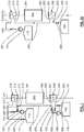
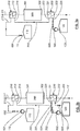
- the device according to the invention illustrated in figure 1 can operate according to two strategies of operation: without or with recirculation illustrated respectively with Figures 2a-3a and 2b- 3b . Note that in these figures are shown only the elements of the device used for the charging or discharging step. The operation with recirculation allows a greater flexibility of operation.
- the two pumps 501, 502 operate simultaneously to allow remixing by the recirculating branches 701, 702 on the second fluid circuit at intermediate points 215, 225 located between the two exchangers 210, 220.
- This remixing takes place with fluid from of the hot tank 110 in charge, and with fluid from the cold tank 120 in discharge.
- a set of control valves 601, 602, 603, 604, 605 and 606 are provided for this purpose.
- the advantage of the strategy without recirculation is that it makes it possible to use a lower mass of the storage material, here constituted by the second fluid. However, it does not allow such fine control of tank temperatures as allowed in the recirculation strategy.
- the temperature of the tanks is adjusted by the recirculation flow rate to control the temperature of the second fluid at an intermediate point 240 to the two exchangers 210, 220, which can also in some cases avoid discharge to obtain under-saturated boiling phenomena in the exchanger 220, and in some cases to avoid filler to obtain super-saturated condensation phenomena in the exchanger 210.
- a flow of the second fluid from the cold tank 120 may be mixed at the recirculation branch 702, at the recirculation point 225, with that arriving since the fourth port 214 of the first exchanger 210 or conversely in load according to the need to increase the temperature of the second fluid before passing through the first exchanger 210, a flow of the second fluid from the hot tank 110 can be mixed, at the level of the recirculation branch 701 at the recirculation point 215, with that arriving at the third port 223 of the second exchanger 220.
- the first heat transfer fluid arrives at high temperature around for example the 470 ° C by a connection means in the first exchanger 210 where it gives heat to the second fluid. It then passes through the latent storage module 300 where it transfers energy to the phase change material, causing the phase change for example by melting the latter. The first fluid finally crosses the second heat exchanger where it yields again heat to the second fluid. At the outlet of the second exchanger 220, the first fluid, having yielded heat, is close to a temperature of, for example, 220 ° C.
- the first fluid arrives at low temperature by a connection means in the second heat exchanger 220 where it recovers heat from the second fluid. It then passes through the latent storage module 300 where it exchanges energy with the phase-change phase-change material. It then passes through the first exchanger 210 where it recovers heat from the second fluid.
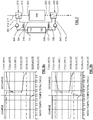
- the figure 4 represents the variations of the temperatures of the first fluid measured at the terminals 301, 302 of the latent storage module 300 on a charge and discharge cycle, obtained by simulation / modeling.
- the x-axis represents the ratio between the elapsed time and the total time of a charge + discharge cycle, and the ordinate axis represents the temperatures, no value is given on this axis.
- the first temperature curve 1100 represents the temperature of the first fluid detected between the first exchanger 210 and the latent storage module 300 input on a charge-discharge cycle, terminal 301; in the case of water, the first fluid occurring on this path in the form of superheated or saturated steam.
- the second temperature curve 1200 represents the temperature of the first fluid between the output of the latent storage module 300 and the second exchanger 220 on a charge-discharge cycle, terminal 302; in the case of water, the first fluid then occurring on this path in the form of subcooled liquid water.
- the load of the latent storage module 300 starts at a time t1 with a stabilization of the first temperature curve 1100 at terminal 301 up to a time t2.
- the temperature plateau corresponds to the nominal point of load of the latent storage module 300; the charge ending shortly after time t2.
- the second temperature curve 1200 which makes it possible to follow the temperature of the condensed water recorded at the terminal 302 is almost constant.
- the latent storage module 300 does not which can provide a constant but decreasing power, since the latent storage module 300 remains passive, the flow rate of steam produced will also decrease with time, implying a decreasing flow rate of the turbine and consequently a pressure in the device which will decrease during of the discharge.
- the temperature at the exit of the latent storage module 300, terminal 301 being the water saturation temperature, it decreases, curve 1100, depending on the pressure. This is the appearance of the first temperature curve 1100 between times t2 and t3; the time t3 corresponding to the discharge end time.
- the latent storage module 300 is isolated for the night (end of the cycle).
- the latent storage module 300 being passive, the power delivered by it is not mastered and is not fixed in time but decreasing. This implies a steam flow curve produced "slippery" over time, confers figure 5 described below.
- the pressure curve, not shown, follows the same trend since it is dependent on the flow rate sent to the turbine.
- the figure 5 illustrating the flow rate of the first fluid at the terminal 301 indicates that this flow is constant and positive during the charge and negative during the discharge, the first fluid then flowing in the opposite direction.
- the superheated steam flow curve entering latent heat storage module 300 follows the sunlight at first order, giving a bell-shaped evolution between times t1. and t2.
- the latent storage module 300 being passive, the power delivered by it is not mastered and is not fixed in time but decreasing. This implies that the vapor flow curve exiting the latent heat storage module 300 is "slippery" with time.
- a modeling step of dynamic type of the device is first carried out, the storage of a plant having a continuously transient operation.
- the latent storage stage is reduced to a single tube without edge effects.
- the equations for mass balance, energy balance and momentum balance are solved for each of the two phases (liquid and vapor).
- the model used makes it possible to simulate the operation of the storage device with a coupling calculation between the latent and sensitive stages realized outside the model of the latent stage.
- the first and second temperature curves 1100, 1200 have been exploited in a more global calculation taking into account the first heat exchanger 210 exchanging the temperatures of the first fluid (in vapor form) and the second fluid (in the form of molten salts) for the high temperature stage 110 and the second exchanger 220 exchanging the temperatures of the first fluid (in the form of liquid water) and the second fluid (in the form of molten salts) for the low temperature stage 120.
- the first and second exchangers 210, 220 have a fixed exchange surface and their overall exchange coefficient, depends on the flow rates of the two fluids following appropriate laws.
- the temperature curves of the first fluid along the first fluid circuit are generally stable, the variations noted after the start of the discharge result from the reversal of the flow direction of the first fluid.
- the first fluid is water
- the temperature curves of the second fluid along the second fluid circuit are stable for the hot and cold tanks, respectively points 213 and 224.
- the temperature at the intermediate point 240 varies between the charge and the discharge.
- the temperature curves of the first fluid along the first fluid circuit are generally stable and are equivalent to the graph without recirculation 6a.
- the curves of the temperatures of the second fluid along the second fluid circuit are stable for hot and cold tanks, respectively points 213 and 224.
- the temperature at the intermediate point 240 corresponding on these curves to the temperature at point 214 and / or 223; 223 in charge and 214 in discharge varies between charging and discharging as in the case of operation without recirculation.
- the flow rates of the second fluid at the inlet and / or at the outlet of the different high and low temperature storage stages are different here because of the recirculation of the second fluid respectively in the recirculation branches 701, 702.
- the heat storage method preferably comprises a charging step and a discharging step.
- the charging step is for storing heat in the first stage 110 of high temperature sensitive heat storage and in the latent stage.
- the charging step comprises determining a set temperature for the first fluid at the access 212 of the heat exchanger 210 or a first set temperature in the first stage 110 of high temperature sensitive heat storage. of the sensible heat storage module and the adaptation of the flow rate of the second fluid at the outlet and / or at the inlet of each of the first and second stages 110, 120, making it possible to maintain these target temperatures.
- the discharge step for its part, is intended to release heat from the first stage 110 of high temperature sensitive heat storage.
- the discharge step comprises determining a set temperature for the first fluid at the access 221 of the heat exchanger 220 or a second constant setpoint temperature in the second storage stage 120 of low sensible heat. temperature of the sensible heat storage module and the adaptation of the flow rate of the second fluid at the outlet and / or inlet of each of the first and second stages 110, 120, to maintain these target temperatures.
- the flow rates for loading and unloading are regulated by controlling the speed of the circulation equipment (pump or fan) and / or by opening control valves 601, 602, 603, 604, 605, 606 positioned on the second fluid circuit. .
- the set temperature for the first fluid at the access 212 of the first exchanger 210 is chosen to correspond to a temperature slightly greater than the change of state of the first fluid, in the case water equivalent to the temperature of a superheated steam.
- the set temperature for the first fluid at the access 221 of the second heat exchanger 220 is chosen to correspond to a temperature slightly lower than the change of state of a first fluid, in the case of the water equivalent to cooled water.
- the second temperature in the first stage 110 of high temperature sensitive heat storage of the sensible heat storage module is determined by the previous load.
- the first temperature in the second floor 120 of Low temperature sensible heat storage of the sensible heat storage module is determined by the previous discharge.
- the first temperature of the second stage 120 recorded during the charging step is consistent with the temperature of the second stage 120 recorded during the preceding discharge step
- the second temperature of the first stage 110 recorded during the the discharging step is consistent with the first temperature of the second stage 110 noted during the preceding charging step.
- the average temperature in the first stage 110 of high temperature sensitive heat storage can remain at the same temperature during a charge-discharge cycle.
- the temperature of the second fluid at the point 213 of the first exchanger 210 during the energy charge can vary around a set value with a tolerance depending on the target performances of the storage installation. .
- the temperature of the second fluid at the point 224 of the second exchanger 220 during the energy discharge may vary around a set value with a tolerance depending on the target performance of the storage facility.
- the mass of the second fluid used during charging in the first stage 110 of high temperature sensitive heat storage is advantageously identical to that used in the second low temperature sensitive heat storage stage 120 during the discharge.
- the energy involved in the latent storage module remains the same during charging and discharging.
- the present invention can be applied to all storages using heat exchangers and a storage material, which can be directly the second fluid or an additional material added to the system, in fluid form or not.
- the molten salts of the sensible heat storage module can be replaced by air exchanging the heat of water or steam through the heat exchangers.
- the energy storage is carried out for example in a bed of rocks or a stack of bricks arranged for each high temperature and low temperature sensitive heat storage stage 110, 120 of the sensible heat storage module. According to this embodiment, it is possible to combine the two stages of heat storage sensitive high temperature and low temperature 110, 120 in a single interior volume preferentially contained in a tank 100 (advantageously comprising an internal bed of rocks).
- the figure 7 illustrates a non-limiting embodiment of the present invention wherein the second fluid, in this example air, exchanges with two different media: the first fluid at first at the exchangers and the storage material present in the tank 100 in a second time.
- the second fluid in this example air
- the first high temperature sensible heat storage stage 110 and the second low temperature sensitive heat storage stage 120 are combined to form a single interior volume of the tank 100.
- the tank 100 comprises a porous material and / or structured contained in the interior volume.
- the first fluid is preferably in the form of water vapor when it passes through the first exchanger 210 or in the form of liquid water as it passes through the second exchanger 220.
- the storage material present in the tank 100 may for example be a bed of rocks or an internal assembly of bricks.
- a porous material is understood to be a material having pores such as rocks and a structured material is understood to be a material having a structure having an arrangement of structured depressions such as bricks.
- the second fluid, the air in this embodiment is here only a medium. In this example, it is advantageously possible to use a single bed of rocks for storing the sensitive energy of the high and low temperature stages 110, 120, the second fluid, the air, passing through the first and second exchangers. 210, 220 connected in series to recover, during charging, the heat successively in the form of water vapor and water sub-cooled.
- the tank is filled with a storage material of the bed rock or brick type.
- the second fluid can be molten salts thus forming a "dual thermocline", making it possible to minimize the quantities of molten salts and therefore the costs compared to the solution having two distinct tanks of molten salts.
- This solution is more expensive (in capital) than a solution using air, but it presents a lower operating cost by the use of pumps (and not fans for air) as means of circulation of the fluid.
Landscapes
- Engineering & Computer Science (AREA)
- Mechanical Engineering (AREA)
- General Engineering & Computer Science (AREA)
- Physics & Mathematics (AREA)
- Thermal Sciences (AREA)
- Chemical & Material Sciences (AREA)
- Combustion & Propulsion (AREA)
- Engine Equipment That Uses Special Cycles (AREA)
Priority Applications (1)
| Application Number | Priority Date | Filing Date | Title |
|---|---|---|---|
| PL16722219T PL3295106T3 (pl) | 2015-05-13 | 2016-05-12 | Urządzenie do magazynowania energii cieplnej |
Applications Claiming Priority (2)
| Application Number | Priority Date | Filing Date | Title |
|---|---|---|---|
| FR1554297A FR3036177B1 (fr) | 2015-05-13 | 2015-05-13 | Dispositif de stockage d'energie thermique |
| PCT/EP2016/060689 WO2016180923A1 (fr) | 2015-05-13 | 2016-05-12 | Dispositif de stockage d'énergie thermique |
Publications (2)
| Publication Number | Publication Date |
|---|---|
| EP3295106A1 EP3295106A1 (fr) | 2018-03-21 |
| EP3295106B1 true EP3295106B1 (fr) | 2019-03-13 |
Family
ID=54065998
Family Applications (1)
| Application Number | Title | Priority Date | Filing Date |
|---|---|---|---|
| EP16722219.9A Active EP3295106B1 (fr) | 2015-05-13 | 2016-05-12 | Dispositif de stockage d'énergie thermique |
Country Status (5)
| Country | Link |
|---|---|
| EP (1) | EP3295106B1 (pl) |
| DK (1) | DK3295106T3 (pl) |
| FR (1) | FR3036177B1 (pl) |
| PL (1) | PL3295106T3 (pl) |
| WO (1) | WO2016180923A1 (pl) |
Families Citing this family (3)
| Publication number | Priority date | Publication date | Assignee | Title |
|---|---|---|---|---|
| CN107062974A (zh) * | 2017-05-31 | 2017-08-18 | 青岛奥环新能源集团有限公司 | 高效热能梯级储存装置 |
| CN108758586B (zh) * | 2018-07-18 | 2024-02-27 | 深圳市爱能森设备技术有限公司 | 一种清洁能源储能蒸汽发生系统 |
| DE102020206376A1 (de) * | 2020-05-20 | 2021-11-25 | Siemens Aktiengesellschaft | Verfahren zum Betrieb eines Schichtenspeichers sowie Schichtenspeicher |
Family Cites Families (3)
| Publication number | Priority date | Publication date | Assignee | Title |
|---|---|---|---|---|
| GB2493950B (en) * | 2011-08-24 | 2016-01-06 | Isentropic Ltd | Energy storage apparatus |
| DE102011053322A1 (de) * | 2011-09-06 | 2013-03-07 | Novatec Solar Gmbh | Verfahren und Vorrichtung zur Speicherung und Rückgewinnung von thermischer Energie |
| GB2516453A (en) * | 2013-07-22 | 2015-01-28 | Isentropic Ltd | Thermal storage apparatus for rapid cycling applications |
-
2015
- 2015-05-13 FR FR1554297A patent/FR3036177B1/fr not_active Expired - Fee Related
-
2016
- 2016-05-12 DK DK16722219.9T patent/DK3295106T3/da active
- 2016-05-12 EP EP16722219.9A patent/EP3295106B1/fr active Active
- 2016-05-12 WO PCT/EP2016/060689 patent/WO2016180923A1/fr not_active Ceased
- 2016-05-12 PL PL16722219T patent/PL3295106T3/pl unknown
Non-Patent Citations (1)
| Title |
|---|
| None * |
Also Published As
| Publication number | Publication date |
|---|---|
| PL3295106T3 (pl) | 2019-08-30 |
| DK3295106T3 (da) | 2019-05-13 |
| FR3036177B1 (fr) | 2017-04-21 |
| FR3036177A1 (fr) | 2016-11-18 |
| WO2016180923A1 (fr) | 2016-11-17 |
| EP3295106A1 (fr) | 2018-03-21 |
Similar Documents
| Publication | Publication Date | Title |
|---|---|---|
| EP2904220B1 (fr) | Systeme de stockage thermique de vapeur | |
| EP3176529B1 (fr) | Systeme et procede de stockage et de restitution d'energie par gaz comprime | |
| EP3295106B1 (fr) | Dispositif de stockage d'énergie thermique | |
| FR2893123A1 (fr) | Procede de controle du stockage d'energie thermique dans le sol et dispositif associe | |
| WO2015140297A1 (fr) | Dispositif de stockage thermique sous forme de chaleur latente a phase de charge ameliorée | |
| EP2795714B1 (fr) | Dispositif de stockage de chaleur pour rechauffer une batterie de vehicule | |
| EP2984434B1 (fr) | Systeme de stockage par voie thermochimique a efficacite de stockage amélioree | |
| EP3721152B1 (fr) | Pompe à chaleur thermochimique et procédé de redistribution d'énergie calorifique à puissance variable | |
| EP3339729A1 (fr) | Dispositif de generation de vapeur utilisant une source de chaleur a basse temperature | |
| WO2013014178A1 (fr) | Dispositif de stockage des energies renouvelables sous la forme de chaleur et le procede de restitution en tri generation | |
| EP2791595B1 (fr) | Procédé de régulation d'un système de refroidissement cryogénique | |
| EP2971760A1 (fr) | Centrale solaire a concentration a fonctionnement ameliore | |
| EP3214398A1 (fr) | Dispositif de stockage d'énergie par matériau à changement de phase incluant une charge électrique intégrée dans le circuit du fluide caloporteur | |
| EP3423772B1 (fr) | Reservoir de stockage de chaleur a fonctionnement optimise | |
| EP3882555B1 (fr) | Unité de valorisation, dispositif de stérilisation comprenant l'unité de valorisation et procédé associé | |
| FR2927160A1 (fr) | Procede et dispositif de chauffage et/ou de refroidissement utilisant l'eau des profondeurs sous-marines en tant que source froide ou source chaude | |
| WO2025242986A1 (fr) | Dispositif de chauffage d'un carburant dans un circuit d'alimentation d'une turbomachine d'aeronef, turbomachine d'aeronef et procede de chauffage d'un carburant correspondant | |
| FR3028308A1 (fr) | Dispositif et methode de stockage et de restitution d'energie calorifique | |
| FR2831949A1 (fr) | Dispositif, procede et installation de regulation de la temperature d'un fluide | |
| FR3050263A1 (fr) | Dispositif de stockage d'energie thermique par materiau a changement de phase comprenant un element permettant de creer une perte de charge | |
| EP3194874A1 (fr) | Caloduc et procédé de réalisation d'un caloduc. | |
| FR3013427A1 (fr) | Centrale solaire | |
| FR3051512A1 (fr) | Systeme de production d'energie thermique a au moins un accumulateur de vapeur de stockage d'energie thermique provenant d'une installation solaire | |
| FR3034178A1 (fr) | Dispositif de chauffage de l'eau dans une cuve d'un chauffe-eau |
Legal Events
| Date | Code | Title | Description |
|---|---|---|---|
| STAA | Information on the status of an ep patent application or granted ep patent |
Free format text: STATUS: THE INTERNATIONAL PUBLICATION HAS BEEN MADE |
|
| PUAI | Public reference made under article 153(3) epc to a published international application that has entered the european phase |
Free format text: ORIGINAL CODE: 0009012 |
|
| STAA | Information on the status of an ep patent application or granted ep patent |
Free format text: STATUS: REQUEST FOR EXAMINATION WAS MADE |
|
| 17P | Request for examination filed |
Effective date: 20171110 |
|
| AK | Designated contracting states |
Kind code of ref document: A1 Designated state(s): AL AT BE BG CH CY CZ DE DK EE ES FI FR GB GR HR HU IE IS IT LI LT LU LV MC MK MT NL NO PL PT RO RS SE SI SK SM TR |
|
| AX | Request for extension of the european patent |
Extension state: BA ME |
|
| DAV | Request for validation of the european patent (deleted) | ||
| DAX | Request for extension of the european patent (deleted) | ||
| GRAP | Despatch of communication of intention to grant a patent |
Free format text: ORIGINAL CODE: EPIDOSNIGR1 |
|
| STAA | Information on the status of an ep patent application or granted ep patent |
Free format text: STATUS: GRANT OF PATENT IS INTENDED |
|
| RIC1 | Information provided on ipc code assigned before grant |
Ipc: F01K 5/00 20060101ALI20180821BHEP Ipc: F01K 3/12 20060101ALI20180821BHEP Ipc: F22B 1/00 20060101ALI20180821BHEP Ipc: F28D 20/02 20060101ALI20180821BHEP Ipc: F28D 20/00 20060101AFI20180821BHEP Ipc: F22B 1/02 20060101ALI20180821BHEP |
|
| INTG | Intention to grant announced |
Effective date: 20180925 |
|
| GRAS | Grant fee paid |
Free format text: ORIGINAL CODE: EPIDOSNIGR3 |
|
| GRAA | (expected) grant |
Free format text: ORIGINAL CODE: 0009210 |
|
| STAA | Information on the status of an ep patent application or granted ep patent |
Free format text: STATUS: THE PATENT HAS BEEN GRANTED |
|
| AK | Designated contracting states |
Kind code of ref document: B1 Designated state(s): AL AT BE BG CH CY CZ DE DK EE ES FI FR GB GR HR HU IE IS IT LI LT LU LV MC MK MT NL NO PL PT RO RS SE SI SK SM TR |
|
| REG | Reference to a national code |
Ref country code: GB Ref legal event code: FG4D Free format text: NOT ENGLISH |
|
| REG | Reference to a national code |
Ref country code: CH Ref legal event code: EP Ref country code: AT Ref legal event code: REF Ref document number: 1108294 Country of ref document: AT Kind code of ref document: T Effective date: 20190315 |
|
| REG | Reference to a national code |
Ref country code: IE Ref legal event code: FG4D Free format text: LANGUAGE OF EP DOCUMENT: FRENCH |
|
| REG | Reference to a national code |
Ref country code: DE Ref legal event code: R096 Ref document number: 602016011073 Country of ref document: DE |
|
| REG | Reference to a national code |
Ref country code: DK Ref legal event code: T3 Effective date: 20190506 |
|
| REG | Reference to a national code |
Ref country code: SE Ref legal event code: TRGR |
|
| REG | Reference to a national code |
Ref country code: NL Ref legal event code: MP Effective date: 20190313 |
|
| REG | Reference to a national code |
Ref country code: LT Ref legal event code: MG4D |
|
| PG25 | Lapsed in a contracting state [announced via postgrant information from national office to epo] |
Ref country code: LT Free format text: LAPSE BECAUSE OF FAILURE TO SUBMIT A TRANSLATION OF THE DESCRIPTION OR TO PAY THE FEE WITHIN THE PRESCRIBED TIME-LIMIT Effective date: 20190313 Ref country code: NO Free format text: LAPSE BECAUSE OF FAILURE TO SUBMIT A TRANSLATION OF THE DESCRIPTION OR TO PAY THE FEE WITHIN THE PRESCRIBED TIME-LIMIT Effective date: 20190613 |
|
| PG25 | Lapsed in a contracting state [announced via postgrant information from national office to epo] |
Ref country code: GR Free format text: LAPSE BECAUSE OF FAILURE TO SUBMIT A TRANSLATION OF THE DESCRIPTION OR TO PAY THE FEE WITHIN THE PRESCRIBED TIME-LIMIT Effective date: 20190614 Ref country code: BG Free format text: LAPSE BECAUSE OF FAILURE TO SUBMIT A TRANSLATION OF THE DESCRIPTION OR TO PAY THE FEE WITHIN THE PRESCRIBED TIME-LIMIT Effective date: 20190613 Ref country code: RS Free format text: LAPSE BECAUSE OF FAILURE TO SUBMIT A TRANSLATION OF THE DESCRIPTION OR TO PAY THE FEE WITHIN THE PRESCRIBED TIME-LIMIT Effective date: 20190313 Ref country code: LV Free format text: LAPSE BECAUSE OF FAILURE TO SUBMIT A TRANSLATION OF THE DESCRIPTION OR TO PAY THE FEE WITHIN THE PRESCRIBED TIME-LIMIT Effective date: 20190313 Ref country code: HR Free format text: LAPSE BECAUSE OF FAILURE TO SUBMIT A TRANSLATION OF THE DESCRIPTION OR TO PAY THE FEE WITHIN THE PRESCRIBED TIME-LIMIT Effective date: 20190313 Ref country code: NL Free format text: LAPSE BECAUSE OF FAILURE TO SUBMIT A TRANSLATION OF THE DESCRIPTION OR TO PAY THE FEE WITHIN THE PRESCRIBED TIME-LIMIT Effective date: 20190313 |
|
| REG | Reference to a national code |
Ref country code: AT Ref legal event code: MK05 Ref document number: 1108294 Country of ref document: AT Kind code of ref document: T Effective date: 20190313 |
|
| PG25 | Lapsed in a contracting state [announced via postgrant information from national office to epo] |
Ref country code: SK Free format text: LAPSE BECAUSE OF FAILURE TO SUBMIT A TRANSLATION OF THE DESCRIPTION OR TO PAY THE FEE WITHIN THE PRESCRIBED TIME-LIMIT Effective date: 20190313 Ref country code: RO Free format text: LAPSE BECAUSE OF FAILURE TO SUBMIT A TRANSLATION OF THE DESCRIPTION OR TO PAY THE FEE WITHIN THE PRESCRIBED TIME-LIMIT Effective date: 20190313 Ref country code: CZ Free format text: LAPSE BECAUSE OF FAILURE TO SUBMIT A TRANSLATION OF THE DESCRIPTION OR TO PAY THE FEE WITHIN THE PRESCRIBED TIME-LIMIT Effective date: 20190313 Ref country code: PT Free format text: LAPSE BECAUSE OF FAILURE TO SUBMIT A TRANSLATION OF THE DESCRIPTION OR TO PAY THE FEE WITHIN THE PRESCRIBED TIME-LIMIT Effective date: 20190713 Ref country code: AL Free format text: LAPSE BECAUSE OF FAILURE TO SUBMIT A TRANSLATION OF THE DESCRIPTION OR TO PAY THE FEE WITHIN THE PRESCRIBED TIME-LIMIT Effective date: 20190313 Ref country code: ES Free format text: LAPSE BECAUSE OF FAILURE TO SUBMIT A TRANSLATION OF THE DESCRIPTION OR TO PAY THE FEE WITHIN THE PRESCRIBED TIME-LIMIT Effective date: 20190313 Ref country code: EE Free format text: LAPSE BECAUSE OF FAILURE TO SUBMIT A TRANSLATION OF THE DESCRIPTION OR TO PAY THE FEE WITHIN THE PRESCRIBED TIME-LIMIT Effective date: 20190313 |
|
| PG25 | Lapsed in a contracting state [announced via postgrant information from national office to epo] |
Ref country code: SM Free format text: LAPSE BECAUSE OF FAILURE TO SUBMIT A TRANSLATION OF THE DESCRIPTION OR TO PAY THE FEE WITHIN THE PRESCRIBED TIME-LIMIT Effective date: 20190313 |
|
| REG | Reference to a national code |
Ref country code: DE Ref legal event code: R097 Ref document number: 602016011073 Country of ref document: DE |
|
| REG | Reference to a national code |
Ref country code: CH Ref legal event code: PL |
|
| PG25 | Lapsed in a contracting state [announced via postgrant information from national office to epo] |
Ref country code: IS Free format text: LAPSE BECAUSE OF FAILURE TO SUBMIT A TRANSLATION OF THE DESCRIPTION OR TO PAY THE FEE WITHIN THE PRESCRIBED TIME-LIMIT Effective date: 20190713 Ref country code: AT Free format text: LAPSE BECAUSE OF FAILURE TO SUBMIT A TRANSLATION OF THE DESCRIPTION OR TO PAY THE FEE WITHIN THE PRESCRIBED TIME-LIMIT Effective date: 20190313 |
|
| PLBE | No opposition filed within time limit |
Free format text: ORIGINAL CODE: 0009261 |
|
| STAA | Information on the status of an ep patent application or granted ep patent |
Free format text: STATUS: NO OPPOSITION FILED WITHIN TIME LIMIT |
|
| PG25 | Lapsed in a contracting state [announced via postgrant information from national office to epo] |
Ref country code: MC Free format text: LAPSE BECAUSE OF FAILURE TO SUBMIT A TRANSLATION OF THE DESCRIPTION OR TO PAY THE FEE WITHIN THE PRESCRIBED TIME-LIMIT Effective date: 20190313 Ref country code: CH Free format text: LAPSE BECAUSE OF NON-PAYMENT OF DUE FEES Effective date: 20190531 Ref country code: LI Free format text: LAPSE BECAUSE OF NON-PAYMENT OF DUE FEES Effective date: 20190531 |
|
| REG | Reference to a national code |
Ref country code: BE Ref legal event code: MM Effective date: 20190531 |
|
| 26N | No opposition filed |
Effective date: 20191216 |
|
| PG25 | Lapsed in a contracting state [announced via postgrant information from national office to epo] |
Ref country code: SI Free format text: LAPSE BECAUSE OF FAILURE TO SUBMIT A TRANSLATION OF THE DESCRIPTION OR TO PAY THE FEE WITHIN THE PRESCRIBED TIME-LIMIT Effective date: 20190313 Ref country code: LU Free format text: LAPSE BECAUSE OF NON-PAYMENT OF DUE FEES Effective date: 20190512 |
|
| PG25 | Lapsed in a contracting state [announced via postgrant information from national office to epo] |
Ref country code: TR Free format text: LAPSE BECAUSE OF FAILURE TO SUBMIT A TRANSLATION OF THE DESCRIPTION OR TO PAY THE FEE WITHIN THE PRESCRIBED TIME-LIMIT Effective date: 20190313 |
|
| PG25 | Lapsed in a contracting state [announced via postgrant information from national office to epo] |
Ref country code: IE Free format text: LAPSE BECAUSE OF NON-PAYMENT OF DUE FEES Effective date: 20190512 |
|
| PG25 | Lapsed in a contracting state [announced via postgrant information from national office to epo] |
Ref country code: BE Free format text: LAPSE BECAUSE OF NON-PAYMENT OF DUE FEES Effective date: 20190531 |
|
| PG25 | Lapsed in a contracting state [announced via postgrant information from national office to epo] |
Ref country code: CY Free format text: LAPSE BECAUSE OF FAILURE TO SUBMIT A TRANSLATION OF THE DESCRIPTION OR TO PAY THE FEE WITHIN THE PRESCRIBED TIME-LIMIT Effective date: 20190313 |
|
| PG25 | Lapsed in a contracting state [announced via postgrant information from national office to epo] |
Ref country code: MT Free format text: LAPSE BECAUSE OF FAILURE TO SUBMIT A TRANSLATION OF THE DESCRIPTION OR TO PAY THE FEE WITHIN THE PRESCRIBED TIME-LIMIT Effective date: 20190313 Ref country code: HU Free format text: LAPSE BECAUSE OF FAILURE TO SUBMIT A TRANSLATION OF THE DESCRIPTION OR TO PAY THE FEE WITHIN THE PRESCRIBED TIME-LIMIT; INVALID AB INITIO Effective date: 20160512 |
|
| PG25 | Lapsed in a contracting state [announced via postgrant information from national office to epo] |
Ref country code: MK Free format text: LAPSE BECAUSE OF FAILURE TO SUBMIT A TRANSLATION OF THE DESCRIPTION OR TO PAY THE FEE WITHIN THE PRESCRIBED TIME-LIMIT Effective date: 20190313 |
|
| PGFP | Annual fee paid to national office [announced via postgrant information from national office to epo] |
Ref country code: GB Payment date: 20240521 Year of fee payment: 9 |
|
| PGFP | Annual fee paid to national office [announced via postgrant information from national office to epo] |
Ref country code: DK Payment date: 20240522 Year of fee payment: 9 |
|
| PGFP | Annual fee paid to national office [announced via postgrant information from national office to epo] |
Ref country code: FI Payment date: 20240521 Year of fee payment: 9 |
|
| PGFP | Annual fee paid to national office [announced via postgrant information from national office to epo] |
Ref country code: PL Payment date: 20240510 Year of fee payment: 9 |
|
| PGFP | Annual fee paid to national office [announced via postgrant information from national office to epo] |
Ref country code: SE Payment date: 20240522 Year of fee payment: 9 |
|
| PGFP | Annual fee paid to national office [announced via postgrant information from national office to epo] |
Ref country code: IT Payment date: 20240531 Year of fee payment: 9 |
|
| PGFP | Annual fee paid to national office [announced via postgrant information from national office to epo] |
Ref country code: DE Payment date: 20250519 Year of fee payment: 10 |
|
| PGFP | Annual fee paid to national office [announced via postgrant information from national office to epo] |
Ref country code: FR Payment date: 20250526 Year of fee payment: 10 |
|
| REG | Reference to a national code |
Ref country code: DK Ref legal event code: EBP Effective date: 20250531 |
|
| PG25 | Lapsed in a contracting state [announced via postgrant information from national office to epo] |
Ref country code: FI Free format text: LAPSE BECAUSE OF NON-PAYMENT OF DUE FEES Effective date: 20250512 |
|
| PG25 | Lapsed in a contracting state [announced via postgrant information from national office to epo] |
Ref country code: SE Free format text: LAPSE BECAUSE OF NON-PAYMENT OF DUE FEES Effective date: 20250513 |
|
| REG | Reference to a national code |
Ref country code: SE Ref legal event code: EUG |
|
| GBPC | Gb: european patent ceased through non-payment of renewal fee |
Effective date: 20250512 |
|
| PG25 | Lapsed in a contracting state [announced via postgrant information from national office to epo] |
Ref country code: GB Free format text: LAPSE BECAUSE OF NON-PAYMENT OF DUE FEES Effective date: 20250512 |
|
| PG25 | Lapsed in a contracting state [announced via postgrant information from national office to epo] |
Ref country code: DK Free format text: LAPSE BECAUSE OF NON-PAYMENT OF DUE FEES Effective date: 20250531 |
|
| PG25 | Lapsed in a contracting state [announced via postgrant information from national office to epo] |
Ref country code: IT Free format text: LAPSE BECAUSE OF NON-PAYMENT OF DUE FEES Effective date: 20250512 |