EP3295267B1 - Appareil de traitement de sols et procédé pour sa navigation ainsi que multitude d'appareils de traitement de sols et procédé pour leur navigation commune - Google Patents
Appareil de traitement de sols et procédé pour sa navigation ainsi que multitude d'appareils de traitement de sols et procédé pour leur navigation commune Download PDFInfo
- Publication number
- EP3295267B1 EP3295267B1 EP16721634.0A EP16721634A EP3295267B1 EP 3295267 B1 EP3295267 B1 EP 3295267B1 EP 16721634 A EP16721634 A EP 16721634A EP 3295267 B1 EP3295267 B1 EP 3295267B1
- Authority
- EP
- European Patent Office
- Prior art keywords
- surroundings
- floor treatment
- images
- treatment device
- image
- Prior art date
- Legal status (The legal status is an assumption and is not a legal conclusion. Google has not performed a legal analysis and makes no representation as to the accuracy of the status listed.)
- Active
Links
Images

Classifications
-
- G—PHYSICS
- G05—CONTROLLING; REGULATING
- G05D—SYSTEMS FOR CONTROLLING OR REGULATING NON-ELECTRIC VARIABLES
- G05D1/00—Control of position, course, altitude or attitude of land, water, air or space vehicles, e.g. using automatic pilots
- G05D1/02—Control of position or course in two dimensions
- G05D1/021—Control of position or course in two dimensions specially adapted to land vehicles
- G05D1/0212—Control of position or course in two dimensions specially adapted to land vehicles with means for defining a desired trajectory
- G05D1/0219—Control of position or course in two dimensions specially adapted to land vehicles with means for defining a desired trajectory ensuring the processing of the whole working surface
-
- A—HUMAN NECESSITIES
- A47—FURNITURE; DOMESTIC ARTICLES OR APPLIANCES; COFFEE MILLS; SPICE MILLS; SUCTION CLEANERS IN GENERAL
- A47L—DOMESTIC WASHING OR CLEANING; SUCTION CLEANERS IN GENERAL
- A47L9/00—Details or accessories of suction cleaners, e.g. mechanical means for controlling the suction or for effecting pulsating action; Storing devices specially adapted to suction cleaners or parts thereof; Carrying-vehicles specially adapted for suction cleaners
- A47L9/28—Installation of the electric equipment, e.g. adaptation or attachment to the suction cleaner; Controlling suction cleaners by electric means
-
- G—PHYSICS
- G01—MEASURING; TESTING
- G01C—MEASURING DISTANCES, LEVELS OR BEARINGS; SURVEYING; NAVIGATION; GYROSCOPIC INSTRUMENTS; PHOTOGRAMMETRY OR VIDEOGRAMMETRY
- G01C21/00—Navigation; Navigational instruments not provided for in groups G01C1/00 - G01C19/00
- G01C21/20—Instruments for performing navigational calculations
- G01C21/206—Instruments for performing navigational calculations specially adapted for indoor navigation
-
- G—PHYSICS
- G05—CONTROLLING; REGULATING
- G05D—SYSTEMS FOR CONTROLLING OR REGULATING NON-ELECTRIC VARIABLES
- G05D1/00—Control of position, course, altitude or attitude of land, water, air or space vehicles, e.g. using automatic pilots
- G05D1/02—Control of position or course in two dimensions
- G05D1/021—Control of position or course in two dimensions specially adapted to land vehicles
- G05D1/0231—Control of position or course in two dimensions specially adapted to land vehicles using optical position detecting means
- G05D1/0238—Control of position or course in two dimensions specially adapted to land vehicles using optical position detecting means using obstacle or wall sensors
- G05D1/024—Control of position or course in two dimensions specially adapted to land vehicles using optical position detecting means using obstacle or wall sensors in combination with a laser
-
- G—PHYSICS
- G05—CONTROLLING; REGULATING
- G05D—SYSTEMS FOR CONTROLLING OR REGULATING NON-ELECTRIC VARIABLES
- G05D1/00—Control of position, course, altitude or attitude of land, water, air or space vehicles, e.g. using automatic pilots
- G05D1/02—Control of position or course in two dimensions
- G05D1/021—Control of position or course in two dimensions specially adapted to land vehicles
- G05D1/0231—Control of position or course in two dimensions specially adapted to land vehicles using optical position detecting means
- G05D1/0246—Control of position or course in two dimensions specially adapted to land vehicles using optical position detecting means using a video camera in combination with image processing means
- G05D1/0248—Control of position or course in two dimensions specially adapted to land vehicles using optical position detecting means using a video camera in combination with image processing means in combination with a laser
-
- G—PHYSICS
- G05—CONTROLLING; REGULATING
- G05D—SYSTEMS FOR CONTROLLING OR REGULATING NON-ELECTRIC VARIABLES
- G05D1/00—Control of position, course, altitude or attitude of land, water, air or space vehicles, e.g. using automatic pilots
- G05D1/02—Control of position or course in two dimensions
- G05D1/021—Control of position or course in two dimensions specially adapted to land vehicles
- G05D1/0268—Control of position or course in two dimensions specially adapted to land vehicles using internal positioning means
- G05D1/0272—Control of position or course in two dimensions specially adapted to land vehicles using internal positioning means comprising means for registering the travel distance, e.g. revolutions of wheels
-
- G—PHYSICS
- G05—CONTROLLING; REGULATING
- G05D—SYSTEMS FOR CONTROLLING OR REGULATING NON-ELECTRIC VARIABLES
- G05D1/00—Control of position, course, altitude or attitude of land, water, air or space vehicles, e.g. using automatic pilots
- G05D1/02—Control of position or course in two dimensions
- G05D1/021—Control of position or course in two dimensions specially adapted to land vehicles
- G05D1/0268—Control of position or course in two dimensions specially adapted to land vehicles using internal positioning means
- G05D1/0274—Control of position or course in two dimensions specially adapted to land vehicles using internal positioning means using mapping information stored in a memory device
-
- G—PHYSICS
- G05—CONTROLLING; REGULATING
- G05D—SYSTEMS FOR CONTROLLING OR REGULATING NON-ELECTRIC VARIABLES
- G05D1/00—Control of position, course, altitude or attitude of land, water, air or space vehicles, e.g. using automatic pilots
- G05D1/02—Control of position or course in two dimensions
- G05D1/021—Control of position or course in two dimensions specially adapted to land vehicles
- G05D1/0287—Control of position or course in two dimensions specially adapted to land vehicles involving a plurality of land vehicles, e.g. fleet or convoy travelling
- G05D1/0291—Fleet control
- G05D1/0297—Fleet control by controlling means in a control room
-
- G—PHYSICS
- G06—COMPUTING OR CALCULATING; COUNTING
- G06F—ELECTRIC DIGITAL DATA PROCESSING
- G06F16/00—Information retrieval; Database structures therefor; File system structures therefor
- G06F16/20—Information retrieval; Database structures therefor; File system structures therefor of structured data, e.g. relational data
- G06F16/29—Geographical information databases
-
- G—PHYSICS
- G06—COMPUTING OR CALCULATING; COUNTING
- G06F—ELECTRIC DIGITAL DATA PROCESSING
- G06F16/00—Information retrieval; Database structures therefor; File system structures therefor
- G06F16/50—Information retrieval; Database structures therefor; File system structures therefor of still image data
- G06F16/58—Retrieval characterised by using metadata, e.g. metadata not derived from the content or metadata generated manually
- G06F16/5866—Retrieval characterised by using metadata, e.g. metadata not derived from the content or metadata generated manually using information manually generated, e.g. tags, keywords, comments, manually generated location and time information
-
- G—PHYSICS
- G06—COMPUTING OR CALCULATING; COUNTING
- G06V—IMAGE OR VIDEO RECOGNITION OR UNDERSTANDING
- G06V20/00—Scenes; Scene-specific elements
- G06V20/50—Context or environment of the image
- G06V20/56—Context or environment of the image exterior to a vehicle by using sensors mounted on the vehicle
- G06V20/58—Recognition of moving objects or obstacles, e.g. vehicles or pedestrians; Recognition of traffic objects, e.g. traffic signs, traffic lights or roads
-
- G—PHYSICS
- G05—CONTROLLING; REGULATING
- G05D—SYSTEMS FOR CONTROLLING OR REGULATING NON-ELECTRIC VARIABLES
- G05D1/00—Control of position, course, altitude or attitude of land, water, air or space vehicles, e.g. using automatic pilots
- G05D1/02—Control of position or course in two dimensions
- G05D1/021—Control of position or course in two dimensions specially adapted to land vehicles
- G05D1/0231—Control of position or course in two dimensions specially adapted to land vehicles using optical position detecting means
- G05D1/0246—Control of position or course in two dimensions specially adapted to land vehicles using optical position detecting means using a video camera in combination with image processing means
-
- G—PHYSICS
- G06—COMPUTING OR CALCULATING; COUNTING
- G06T—IMAGE DATA PROCESSING OR GENERATION, IN GENERAL
- G06T3/00—Geometric image transformations in the plane of the image
- G06T3/60—Rotation of whole images or parts thereof
-
- G—PHYSICS
- G06—COMPUTING OR CALCULATING; COUNTING
- G06V—IMAGE OR VIDEO RECOGNITION OR UNDERSTANDING
- G06V2201/00—Indexing scheme relating to image or video recognition or understanding
- G06V2201/07—Target detection
-
- H—ELECTRICITY
- H04—ELECTRIC COMMUNICATION TECHNIQUE
- H04N—PICTORIAL COMMUNICATION, e.g. TELEVISION
- H04N7/00—Television systems
- H04N7/18—Closed-circuit television [CCTV] systems, i.e. systems in which the video signal is not broadcast
- H04N7/183—Closed-circuit television [CCTV] systems, i.e. systems in which the video signal is not broadcast for receiving images from a single remote source
Definitions
- the invention relates to a method for navigating at least one self-propelled soil cultivation device, preferably a plurality of soil cultivation devices, which work on a soil at the same time, ie in parallel, the drives of a respective soil cultivation device being controlled as a function of obstacle information from obstacles detected by the respective soil cultivation device, with obstacles are at least formed by real objects, such as walls, whose obstacle information is detected by sensors on the respective soil cultivation device, and with a respective soil cultivation device at temporal and / or spatial intervals at locations along the path of movement with a camera that is carried along.
- a large number of soil cultivation implements that work in parallel can thus form a swarm of soil cultivation implements.
- the invention also relates to a soil cultivation device for carrying out the method.
- Self-propelled soil cultivation devices are known in the state of the art in a wide variety of designs. Typical representatives of such soil cultivation devices are vacuum cleaning robots, floor mopping robots or lawnmowing robots. The invention can relate to any type of such soil cultivation devices and preferably to robot vacuum cleaners.
- the soil cultivation devices each have controlled, in particular regulated, drives so that these soil cultivation devices can move automatically over the respective floor surface.
- These drives typically include two independently controllable wheels and a freely rotatable steering roller or ball, with cornering taking place by controlling the wheels at different rotational speeds, in particular what is known as differential steering is thus present.
- the control takes place with an electronics integrated in a device, which takes over the navigation of the device on a floor surface, e.g. depending on sensor signals or calculated values.
- Typical soil cultivation devices can have a device body with, for example, a circular outline, with a soil cultivation device being integrated into the device body on the underside, in particular between the wheels, e.g. a vacuum cleaner or a rotating cutting device.
- the driven wheels can have wheel sensors in order to provide odometry data for the navigation of such a device, e.g. specific distances covered.
- the devices which preferably only move in one plane, have suitable sensors for obstacle detection in the context of navigation, for example collision sensors that react to contact or preferably non-contact sensors, for example designed as laser scanners.
- a soil cultivation device can navigate preferably without collision, in particular carry out a first type of navigation.
- the type of movement path followed is implemented in the electronics in a predetermined manner, usually as a meander path or as a spiral path.
- a predetermined meandering path this means that a soil cultivation device reverses its direction of movement when an obstacle is detected in front of it and moves back at a distance from its own previously traveled path. It does not matter whether the previously driven path ran along a wall or was created freely in space.
- value pairs of angle (under which the device "sees” the obstacle) and the distance (at this angle), for example from the device center to the obstacle, are passed to the algorithm, the algorithm then calculating a distance value to the obstacle transversely, preferably perpendicular to the direction of movement, if it is not also found by sensors , and regulates the wheels to a target value by controlling the drives.
- Local visual homing is a term for a group of methods in which a vector, the so-called home vector, is calculated from two images that were taken at different locations, which determines the direction of the location at which one of the images was taken the location where the other picture was taken. The distance between the two locations is not calculated.
- a distance from the device, for example to a path, along which the soil cultivation device has already traveled and along which the soil cultivation device has already traveled can be determined by triangulation based on at least two home vectors using known distances between the locations who took several pictures himself.
- the device Since the homing process takes place with the images of the surroundings recorded by the device itself and the device travels a predetermined, here meandering path, the device knows which of the surroundings images it has to use for triangulation and distance control on its new path section If the direction is reversed, the device drives past the places in reverse order to which it took pictures of the surroundings on the previous lane.
- the images to be used are selected here on the basis of absolute metric information, via which the required images are accessed.
- the specification of the meandering path takes place in the prior art in that a point is determined on the path to be traveled, which the soil cultivation device is to approach from its current location and the soil cultivation device is controlled accordingly in order to reach the point.
- a point is determined on the path to be traveled, which the soil cultivation device is to approach from its current location and the soil cultivation device is controlled accordingly in order to reach the point.
- it is necessary to have stored the type of path to be traveled in the electronics of the device.
- Each point to be approached must meet the criterion of being on the specified path.
- a path is made up of a large number of default points that are approached one after the other.
- a topological map is formed in a database into which a node is inserted by a respective soil cultivation device for each location where an image of the surroundings, preferably a 360 ° panorama image, is recorded to which at least the image of the surroundings is assigned, and connections are formed between a newly inserted node and at least one node already inserted in the map and already inserted by the same tillage device, to which relative metric information is assigned.
- a preferably purely topological map is constructed according to the invention, with the aid of which the navigation can be carried out in addition to the navigation by means of obstacle sensors, in particular also here on the basis of local visual homing.
- a purely topological map is understood to mean a graph in the mathematical sense in which the nodes characterize locations in space using sensor data recorded there, here at least the panoramic camera image, with connections, also referred to as edges, between the nodes Show mutual availability.
- connections also referred to as edges
- relative metric information about the relative position of the locations e.g. from odometry data, is stored here.
- Each node of the map to be constructed or constructed according to the invention accordingly represents, through the assigned image of the surroundings, a location at which a soil cultivation device was once, without the location with absolute coordinates to provide. Connections between nodes mean that the locations represented by the nodes can be reached. Such connections therefore exist at least between the nodes which are inserted into the map for those locations along which a respective soil cultivation device has traveled.
- the relative metric information assigned to the connections can preferably be formed by the odometric data that are recorded, for example, by the wheel sensors of the respective soil cultivation device, which initiates the entry of a node in the map or carries it out itself.
- the method is carried out with only a single soil cultivation device or by several at the same time.
- Each soil cultivation device participating in the method - that is, if necessary, only one - enters nodes in the map for each location at which it has recorded images of the surroundings.
- a soil cultivation device after a soil cultivation device has entered a node in the map and the image of the surroundings has been assigned, it is determined by comparing the new image of the surroundings at the current location with all images of the surroundings already assigned to nodes in the database, whether in a limited ( spatial) environment of the the current location belonging to the new environment image is at least one neighboring location for which a node and an assigned environment image have already been stored in the map of the same or a different soil cultivation device.
- the aforementioned determination of neighboring locations is restricted to those locations that are located in a defined spatial environment, the environment not having to be defined by metric spatial data. Rather, it can be provided that, during the image comparison, a visual (i.e. non-spatial) distance measure between the current image of the surroundings and all already saved ones is determined and a location is only evaluated as a neighboring place if the visual distance measure falls below a threshold value.
- a visual distance measure between the current image of the surroundings and all already saved ones is determined and a location is only evaluated as a neighboring place if the visual distance measure falls below a threshold value. This is based on the idea that as the spatial distance between the locations decreases, the pictorial distance dimension of the associated images of the surroundings also decreases, i.e. images of the surroundings that are below the specified distance from the current image of the surroundings belong to locations that have a certain spatial - albeit not numerically determined - Distance below.
- the main advantage of this aspect of the method is that regardless of any type of path, the comparison can be used to determine whether a soil cultivation device is in the vicinity of a location or several locations that have already been processed, regardless of whether this processing is carried out was entered in the database or the topological map by the soil cultivation device itself (which provided the current image of the surroundings) or by another soil cultivation device operating in parallel. Since the comparison is carried out for each image of the surroundings newly assigned to a node and for all existing images, several neighboring locations can therefore also be found which meet the comparison criterion, that is to say form a neighboring location in a limited area.
- the invention now provides that if there is at least one such neighboring location found by comparison, proceeding from the newly inserted node to the associated node of each determined neighboring location in the topological map a new connection is inserted, whereby the topological map is supplemented by accessibility information between the locations.
- Another essential aspect of the invention is that new connections have been inserted into the map for at least one, preferably all neighboring locations to their nodes, obstacle information relative to the current location of the new environment image is calculated from the data stored in the map, in the form of relative metric relationships entered in the connections and used to control or regulate the drives of the respective tillage implement.
- This obstacle information can in turn be values of angle and distance, calculated by local visual homing, between the current location and each of the neighboring locations previously found by comparison.
- each neighboring location found by comparison can be evaluated as an obstacle during navigation, namely like a virtual obstacle, which is characterized by an angle value and a distance value relative to the current location, as if it were Obstacle has been measured by sensors, as is done with real obstacles, for example by means of obstacle sensors, such as lasers, which was described at the beginning.
- pairs of values for angle and distance are transferred to a navigation algorithm, as it is known in its type for the real wall tracking described at the beginning, and this algorithm controls the drives or wheels of the respective soil cultivation device as a function of these values, in particular regulates to a certain distance from the virtual obstacle.
- the value pairs of angle and distance are transferred to exactly the same navigation algorithm as a control variable, which also carries out the navigation for real obstacles.
- the navigation or the one for it The stored algorithm does not differentiate between the obstacle values of real or virtual obstacles.
- the virtual obstacles determined according to the invention are treated as if they were real obstacles, with the effect that soil areas that have already been worked by any soil cultivation device are circumvented as virtual obstacles by each soil cultivation device.
- the distance control to the virtual obstacle that is to say to a neighboring location found in each case, can take place in the same way as with the distance control to the real obstacle, such as a wall.
- the invention preferably provides for the soil cultivation to be started along real obstacles.
- One embodiment here can preferably provide that, in the case of regulation relative to a virtual obstacle, a different, preferably larger distance value is specified as the setpoint in the regulation compared to regulation in the case of real obstacles, in particular in order to take into account that a tillage device has already taken place Processing of the ground can drive past the virtual obstacle (neighboring location) at a greater distance than would be the case with a real obstacle, which is to be approached as close as possible.
- determined distance values of a respective value pair of angle and distance value between the current location and a neighboring location determined by comparison are scaled by a factor, in particular so that the distance appears to a soil cultivation device to be smaller than it actually is. In this case it can always be the same Distance value between device and obstacle (viewed perpendicular to the path of the device) can be controlled during navigation without having to differentiate between real and virtual obstacles.
- a respective soil cultivation device moves at a distance along those locations whose nodes / images of the surroundings in the topological map have connections with metric, preferably odometric information based on a node of a determined neighboring location.
- a soil cultivation device can thus drive alongside an already worked path, e.g. in parallel at a controlled distance, whereby this can be done on paths that the same soil cultivation device has already traveled as well as with paths from another soil cultivation device due to the advantageous effects of the invention.
- the images of the surroundings of all soil cultivation devices are stored in a single common database on a central data processing system and / or in a database that is individual for each soil cultivation device on the respective soil cultivation device, in order to generate a single common topological map.
- the contents of all individual databases being identical or each individual database comprising only part of the common map.
- the invention can provide here that the lower edge of the image of the surroundings, preferably the lower edge of the panorama image, has a height such that the multiple soil cultivation devices do not detect themselves in the images of the surroundings.
- the soil cultivation devices can be provided, in particular also via the camera, with which images of the surroundings are recorded.
- the soil cultivation devices do not have to communicate with each other when a central database is formed, they all access the same data, so that each soil cultivation device can thereby obtain knowledge (by determining neighboring locations) of areas where it has already been or where it has already been.
- a further development can provide here that the images of the surroundings are communicated by means of wireless communication from a respective soil cultivation device (of several) to the single common database or the respective individual databases, in particular each soil cultivation device communicates with the central data processing system or with any other soil cultivation device for this purpose.
- the comparison of a current image of the surroundings of each soil cultivation device is carried out according to the invention with all images of the surroundings stored in the common database on the central data processing system, with the determination of the obstacle information mentioned at the beginning for each neighboring location found in a preferred embodiment using local visual homing, preferably between the current location and to several neighboring locations in order to determine several home vectors from which the angular values between the locations result, and to also use these and relative position information to determine distances between the locations by triangulation.
- the invention can provide that determined relative position information between the locations is assigned to those connections that exist between the respective nodes of these locations in the topological map, so that If such locations and nodes are used again, the values stored in the connections can be accessed immediately without these values having to be recalculated.
- the invention can provide that the calculations and assignments of values (distance / angle) take place on the central database or a data processing system managing this and the values are transmitted back to the soil cultivation device that provided the current panorama image for the comparison so that this respective device can transfer the value pairs to its navigation algorithm.
- the invention can also provide that the comparison of a current image of the surroundings with the images of the surroundings stored in the respective individual database is carried out individually by each soil cultivation device and that the obstacle information is determined itself.
- the comparison of a new image of the surroundings with all other stored images of the surroundings is carried out in two stages in order to determine neighboring locations.
- a group of images of the surroundings is determined which meet a first comparison criterion when compared with the new image of the surroundings - for example, the comparison being less strict and / or being calculable more quickly than in the second stage --- and in a second stage, from the group of surroundings images determined in the first stage, those surroundings images are determined that meet a second comparison criterion when compared with the new surroundings image, for example, the comparison being more rigorous and more complex to calculate compared to the first stage.
- Such a procedure can also be carried out in more than two stages.
- An exemplary embodiment can provide that in the first stage, in the current environment image, groups of several image lines are averaged for one line each and, after a Fourier transformation, each averaged line is a distance measure from the absolute values of the Fourier coefficients of this current environment image and the corresponding absolute values of the Fourier coefficients of stored environment images is formed and a group of surroundings images is selected from the stored images, in which the formed distance dimensions each fall below a threshold value.
- the absolute values of the Fourier coefficients form the aforementioned signature.
- the invention can also provide here that the signature to be used later for the comparison is saved as soon as nodes are entered in the map and the image of the surroundings is assigned. For each node and the assigned image in the topological map, there is initially signature information that can be accessed at any time.
- a distance measure is understood to mean a measure that represents image differences between the images and not a spatial distance.
- the distance measure can, for example, be a Euclidean one.
- Discarding phase information and only taking absolute values of the Fourier coefficients into account has the advantage that the image information used for comparison is rotationally invariant and therefore the images to be compared do not first have to be computationally aligned using an image compass.
- the invention can then further provide that in the second stage a distance measure (e.g. Euclidean) is formed from the current environment image to each environment image of the group selected in the first stage, in particular with the calculation of the distance measure for two environment images multiple times while rotating one of the environment images in the azimuth direction is repeated by an angular amount and the minimum of all distance measures is selected as the resulting distance measure, the surroundings images being selected as neighboring locations for those locations whose distance measure falls below a threshold value.
- a distance measure e.g. Euclidean
- the invention preferably provides, after determining the neighboring locations for a current location, the obstacle information required according to the invention for each neighboring location found to calculate, so preferably the angle and the distance at which such a neighboring location is "seen" from the current location by the tillage device.
- the angle values can be calculated using a method for local visual homing between each pair of the current location and the determined neighboring location, since the home vector represents the angle.
- local visual homing can be carried out here using warping methods, for example min-warping.
- warping methods for example min-warping.
- images are calculated that are recorded by a tillage device ("see") if it had moved, whereby the calculated images are compared with the target image, eg image at the neighboring location; however, the images do not necessarily have to be calculated explicitly.
- the comparison can take place on the basis of the assumed movement parameters, the home vector being determined from those movement parameters which provide the best correspondence between the calculated image and the target image.
- a min-warping method has the advantage that azimuth compensation does not have to take place for the images of the surroundings to be compared by means of an image compass.
- the metric distances between the current location and each neighboring location can then be calculated by triangulation, in particular using local visual homing, between these locations and other locations or nodes drawn from the topological map, in particular taking into account connections already in the map relative metric information stored on the associated nodes.
- new metric distance information that is calculated between two locations can be stored in connections of the associated nodes in the map.
- the navigation i.e. the control of the drives of the wheels of a respective soil cultivation device, can then take place as a function of these value pairs, in particular by regulating the distance between the currently driven path and a previous trajectory identified by the neighboring locations.
- a self-propelled soil cultivation device comprises a device for cultivating a soil, in particular a vacuum cleaning device, as well as drives controlled by means of electronics, wherein such a device is also set up, in particular, the electronics are programmed to carry out a method of the type described above.
- An algorithm is preferably implemented in the electronics in the form of a program processed by a microprocessor, which controls the drives of the wheels of the device as a function of pairs of distance values and angle values, which represent the relative spatial relationship between the device and an obstacle. Alternately or even cumulatively, pairs of values of distance and angle to real obstacles (objects) and virtual obstacles are transferred to the algorithm or this executing program part, the latter being formed by locations where a soil cultivation device has already been.
- the device is set up to access a purely topological map in a database in which a node is formed for each such location.
- the Figure 1 shows an example of an apartment with several rooms in which 4 tillage devices 1-4 work on the apartment floor at the same time, eg vacuum.
- All devices 1-4 work with the same navigation method and communicate here via radio, e.g. WLAN, with a central database 5, which is managed on a data processing system and which includes a topological map with nodes for all locations where each of the devices 1- 4 a panorama picture was taken. These places are in the Figure 1 marked by point 6.
- the points here have graphically represented connections in order to identify the paths of movement of each soil cultivation device 1 to 4.
- a device If a device is only surrounded by areas that have already been driven on, i.e. virtual or real obstacles, it searches for free, unprocessed areas, which can be done by detecting the free space using the stored topological map.
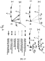
- the Figure 2 clarifies the procedure for each of the tillage implements 1-4.
- part A of the figure Figure 2 is determined at the location of the node E of the path I by comparison, which nodes in the map belong to locations that are close to the location of the node E. These neighboring locations N1, N2, N3 or nodes are indicated by dashed lines in part A of FIG Figure 2 visualized.
- the respective home vector H1, H2, H3 between the current location E and the neighboring location N1, N2, N3 is determined by local visual homing according to part B of the figure. These vectors represent the angle at which the neighboring location N appears relative to the direction of movement from the current location E.
- the distance value between location E and each neighboring location N can be calculated by triangulation.
- a respective distance vector AV represents the angle and the distance between location E and each neighboring location N.
- the value pairs of the distance value and angle of each neighboring location form input parameters for the navigation algorithm of the device in order to control the wheels as a function of this and thus the distance between the tracks To regulate I and II to a desired setpoint.
- the device travels essentially at a constant distance, in particular quasi "parallel" to the preceding lane II of another device.
- the navigation algorithm interprets the locations of this predecessor lane II as obstacles to be driven along, according to the navigation strategy stored in the algorithm.
Landscapes
- Engineering & Computer Science (AREA)
- Physics & Mathematics (AREA)
- Radar, Positioning & Navigation (AREA)
- Remote Sensing (AREA)
- General Physics & Mathematics (AREA)
- Automation & Control Theory (AREA)
- Aviation & Aerospace Engineering (AREA)
- Theoretical Computer Science (AREA)
- Databases & Information Systems (AREA)
- Data Mining & Analysis (AREA)
- General Engineering & Computer Science (AREA)
- Optics & Photonics (AREA)
- Electromagnetism (AREA)
- Multimedia (AREA)
- Library & Information Science (AREA)
- Computer Vision & Pattern Recognition (AREA)
- Mechanical Engineering (AREA)
- Control Of Position, Course, Altitude, Or Attitude Of Moving Bodies (AREA)
- Guiding Agricultural Machines (AREA)
Claims (11)
- Procédé de navigation d'au moins un dispositif de traitement de sol autopropulsé (1, 2, 3, 4), en particulier d'au moins un robot aspirateur (1, 2, 3, 4), de préférence d'une multitude de dispositifs de traitement de sol (1, 2, 3, 4), les entraînements d'un dispositif de traitement de sol respectif (1, 2, 3, 4) étant commandés en fonction d'informations d'obstacles provenant d'obstacles détectés par le dispositif de traitement de sol respectif (1, 2, 3, 4), en particulier en fonction de valeurs de distance et d'angle entre le dispositif de traitement de sol respectif (1, 2, 3, 4) et au moins un obstacle, les obstacles étant au moins formés par des objets réels, et en particulier des murs, dont les informations d'obstacles sont détectées par des capteurs situés au niveau du dispositif de traitement de sol respectif (1, 2, 3, 4), en particulier des scanners laser, et un dispositif de traitement de sol respectif (1, 2, 3, 4) capturant des images d'environnement, en particulier des images panoramiques à 360°, en particulier sur la base desquelles un dispositif de traitement de sol respectif (1, 2, 3, 4) navigue au moyen d'un repérage visuel, à des intervalles de temps et/ou d'espace et à des emplacements (6) le long de la trajectoire au moyen d'une caméra transportée, caractérisé en ce quea. une carte topologique est formée dans une base de données (5), carte dans laquelle un dispositif de traitement de sol respectif (1, 2, 3, 4) insère, pour chaque emplacement (E, 6) où une image d'environnement est acquise, un nœud auquel au moins l'image d'environnement est associée, et forme des liaisons (V) entre un nœud nouvellement inséré et au moins un nœud présent dans la carte et déjà inséré par le même dispositif de traitement de sol (1, 2, 3, 4), liaisons auxquelles sont associées des informations métriques relatives, en particulier qui sont déterminées par des données odométriques du dispositif de traitement de sol respectif (1, 2, 3, 4), etb. une comparaison entre la nouvelle image d'environnement à l'emplacement actuel (E), où un nouveau nœud est inséré dans la carte, et toutes les images d'environnement déjà associées à des nœuds dans la base de données permet de déterminer si au moins un emplacement voisin (N1, N2, N3), pour lequel un nœud et une image d'environnement associée ont déjà été mémorisés dans la carte du même ou d'un autre dispositif de traitement de sol (1, 2, 3, 4), se trouve dans un environnement limité de l'emplacement actuel (E) appartenant à la nouvelle image d'environnement etc. en présence d'au moins un tel emplacement voisin (N1, N2, N3), une nouvelle liaison est insérée dans la carte topologique depuis le nœud nouvellement inséré jusqu'au nœud associé de chaque emplacement voisin déterminé (N1, N2, N3), etd. pour au moins un emplacement voisin, de préférence tous les emplacements voisins (N1, N2, N3), pour les nœuds desquels de nouvelles liaisons ont été insérées dans la carte, des informations d'obstacles sont calculées, notamment à l'aide d'un repérage visuel, par rapport à l'emplacement actuel (E) de la nouvelle image d'environnement à partir des données mémorisées dans la carte, et sont utilisées pour commander ou réguler les entraînements du dispositif de traitement de sol respectif (1, 2, 3, 4).
- Procédé selon la revendication 1, caractérisé en ce qu'un dispositif de traitement de sol respectif (1, 2, 3, 4) continue à se déplacer à distance le long des emplacements dont les nœuds/images d'environnement dans la carte topologique comportent, à partir d'un nœud d'un emplacement voisin déterminé (N1, N2, N3), des liaisons (V) ayant des informations métriques, de préférence odométriques.
- Procédé selon l'une des revendications précédentes, caractérisé en ce que, dans le cas d'une multitude de dispositifs de traitement de sol (1, 2, 3, 4) traitant simultanément un sol, les images d'environnement de tous les dispositifs de traitement de sol sont mémorisées afin de générer une seule carte topologique communea. dans une seule base de données commune (5) d'un système central de traitement de données et/oub. dans une base de données, propre à chaque dispositif de traitement de sol, du dispositif de traitement de sol respectif (1, 2, 3, 4), en particulier les contenus de toutes les bases de données individuelles étant identiques ou chaque base de données individuelle ne comprenant qu'une partie de la carte commune.
- Procédé selon la revendication 3, caractérisé en ce que les images d'environnement sont communiquées au moyen d'une communication sans fil par un dispositif de traitement de sol respectif (1, 2, 3, 4) à la base de données commune unique (5) ou aux bases de données individuelles respectives, en particulier chaque dispositif de traitement de sol (1, 2, 3, 4) communique pour cela avec le système central de traitement des données ou avec tout autre dispositif de traitement de sol (1, 2, 3, 4).
- Procédé selon la revendication 3 ou 4, caractérisé en ce que la comparaison entre une image d'environnement actuelle de chaque dispositif de traitement de sol (1, 2, 3, 4) et toutes les images d'environnement mémorisées dans la base de données commune (5) est effectuée sur le système central de traitement des données et les informations d'obstacles déterminées à l'aide du repérage visuel local, de préférence pour plusieurs emplacements voisins (N1, N2, N3), peuvent être retransmises au dispositif de traitement de sol (1, 2, 3, 4) qui a fourni l'image panoramique actuelle pour la comparaison.
- Procédé selon la revendication 3 ou 4, caractérisé en ce que chaque dispositif de traitement de sol (1, 2, 3, 4) effectue individuellement une comparaison entre une image d'environnement actuelle et les images d'environnement mémorisées dans la base de données individuelle respective et détermine même les informations d'obstacle.
- Procédé selon l'une des revendications précédentes, caractérisé en ce que la comparaison entre une nouvelle image d'environnement et toutes les autres images d'environnement mémorisées est effectuée en deux étapes, un groupe d'images d'environnement, qui satisfont lors d'une comparaison avec la nouvelle image d'environnement à un premier critère de comparaison, en particulier moins strict et calculable plus rapidement, étant déterminé dans une première étape et des images d'environnement, qui satisfont lors de la comparaison avec la nouvelle image d'environnement à un deuxième critère de comparaison, notamment plus strict et plus complexe à calculer, étant déterminées dans une deuxième étape à partir du groupe d'images d'environnement déterminé dans la première étape.
- Procédé selon la revendication 7, caractérisé en ce que dans la première étape dans l'image panoramique actuelle des groupes de plusieurs lignes d'image sont moyennés pour former à chaque fois une ligne et une mesure de distance par rapport aux valeurs absolues des coefficients de Fourier et aux valeurs absolues correspondantes des coefficients de Fourier d'images d'environnement mémorisées est formée après une transformation de Fourier de chaque ligne moyennée et un groupe d'images d'environnement, pour lesquelles les mesures de distance formées tombent au-dessous d'une valeur de seuil, est sélectionné à partir des images mémorisées.
- Procédé selon la revendication 8, caractérisé en ce que, dans la deuxième étape, une mesure de distance de l'image d'environnement actuelle est formée pour chaque image du groupe sélectionné, notamment le calcul de la mesure de distance pour deux images d'environnement étant répété plusieurs fois par rotation de l'une des images d'environnement d'une valeur angulaire dans la direction azimutale, et le minimum de toutes les mesures de distance étant sélectionné, les images d'environnement étant sélectionnées comme emplacement voisin (N1, N2, N3) pour des emplacements dont la distance tombe au-dessous d'une valeur de seuil.
- Procédé de navigation de plusieurs outils de traitement de sol autopropulsés (1, 2, 3, 4), chacun des dispositifs de traitement de sol (1, 2, 3, 4) mettant en œuvre le même procédé de navigation qui comprend un procédé de suivi de mur, un mur à suivre étant formé aussi bien par un mur réel que par un mur virtuel qui est formé par des nœuds dans une carte topologique construite conjointement par tous les dispositifs de traitement de sol (1, 2, 3, 4), en particulier selon l'une des revendications précédentes.
- Dispositif de traitement de sol autopropulsé (1, 2, 3, 4) comprenant un dispositif de traitement de sol, comprenant notamment un aspirateur, et des entraînements commandés par une électronique, caractérisé en ce qu'il est adapté pour mettre en œuvre un procédé selon l'une des revendications précédentes.
Applications Claiming Priority (2)
| Application Number | Priority Date | Filing Date | Title |
|---|---|---|---|
| DE102015006014.7A DE102015006014A1 (de) | 2015-05-13 | 2015-05-13 | Bodenbearbeitungsgerät und Verfahren zu dessen Navigation sowie Schwarm von Bodenbearbeitungsgeräten und Verfahren zu deren gemeinsamer Navigation |
| PCT/EP2016/000662 WO2016180514A1 (fr) | 2015-05-13 | 2016-04-26 | Appareil de traitement de sols et procédé pour sa navigation ainsi que multitude d'appareils de traitement de sols et procédé pour leur navigation commune |
Publications (2)
| Publication Number | Publication Date |
|---|---|
| EP3295267A1 EP3295267A1 (fr) | 2018-03-21 |
| EP3295267B1 true EP3295267B1 (fr) | 2021-06-02 |
Family
ID=55963281
Family Applications (1)
| Application Number | Title | Priority Date | Filing Date |
|---|---|---|---|
| EP16721634.0A Active EP3295267B1 (fr) | 2015-05-13 | 2016-04-26 | Appareil de traitement de sols et procédé pour sa navigation ainsi que multitude d'appareils de traitement de sols et procédé pour leur navigation commune |
Country Status (5)
| Country | Link |
|---|---|
| US (1) | US10345821B2 (fr) |
| EP (1) | EP3295267B1 (fr) |
| JP (1) | JP2018514879A (fr) |
| DE (1) | DE102015006014A1 (fr) |
| WO (1) | WO2016180514A1 (fr) |
Families Citing this family (27)
| Publication number | Priority date | Publication date | Assignee | Title |
|---|---|---|---|---|
| DE102015109775B3 (de) | 2015-06-18 | 2016-09-22 | RobArt GmbH | Optischer Triangulationssensor zur Entfernungsmessung |
| DE102015114883A1 (de) | 2015-09-04 | 2017-03-09 | RobArt GmbH | Identifizierung und Lokalisierung einer Basisstation eines autonomen mobilen Roboters |
| DE102015119501A1 (de) | 2015-11-11 | 2017-05-11 | RobArt GmbH | Unterteilung von Karten für die Roboternavigation |
| DE102015119865B4 (de) | 2015-11-17 | 2023-12-21 | RobArt GmbH | Robotergestützte Bearbeitung einer Oberfläche mittels eines Roboters |
| DE102015121666B3 (de) | 2015-12-11 | 2017-05-24 | RobArt GmbH | Fernsteuerung eines mobilen, autonomen Roboters |
| DE102016102644A1 (de) | 2016-02-15 | 2017-08-17 | RobArt GmbH | Verfahren zur Steuerung eines autonomen mobilen Roboters |
| US20200326722A1 (en) * | 2016-04-25 | 2020-10-15 | Lg Electronics Inc. | Mobile robot, system for multiple mobile robot, and map learning method of mobile robot using artificial intelligence |
| WO2018024897A1 (fr) | 2016-08-05 | 2018-02-08 | RobArt GmbH | Procédé de commande d'un robot mobile autonome |
| CN107121142B (zh) * | 2016-12-30 | 2019-03-19 | 深圳市杉川机器人有限公司 | 移动机器人的拓扑地图创建方法及导航方法 |
| DE102017100366A1 (de) * | 2017-01-10 | 2018-07-12 | Vorwerk & Co. Interholding Gmbh | Verfahren zum Betrieb eines Bodenbearbeitungsgerätes |
| JP2020509500A (ja) | 2017-03-02 | 2020-03-26 | ロブアート ゲーエムベーハーROBART GmbH | 自律移動ロボットの制御方法 |
| DE102017109219A1 (de) | 2017-04-28 | 2018-10-31 | RobArt GmbH | Verfahren für die Roboternavigation |
| DE102017207341A1 (de) | 2017-05-02 | 2018-11-08 | Henkel Ag & Co. Kgaa | Verfahren zur Steuerung von Reinigungsgeräten |
| DE102017113287A1 (de) * | 2017-06-16 | 2018-12-20 | Vorwerk & Co. Interholding Gmbh | System mit mindestens zwei Bodenbearbeitungsgeräten |
| CN107728616B (zh) * | 2017-09-27 | 2019-07-02 | 广东宝乐机器人股份有限公司 | 移动机器人的地图创建方法及移动机器人 |
| CN108278994A (zh) * | 2017-12-07 | 2018-07-13 | 北京臻迪科技股份有限公司 | 一种小型无人船水下测绘方法及设备 |
| CN108008728B (zh) * | 2017-12-12 | 2020-01-17 | 深圳市银星智能科技股份有限公司 | 清洁机器人以及基于清洁机器人的最短路径规划方法 |
| JP7025990B2 (ja) * | 2018-05-14 | 2022-02-25 | 日立グローバルライフソリューションズ株式会社 | 移動体、および、移動体の地図共有方法 |
| US10678264B2 (en) * | 2018-10-10 | 2020-06-09 | Midea Group Co., Ltd. | Method and system for providing remote robotic control |
| CN110050524A (zh) * | 2019-06-06 | 2019-07-26 | 广州思谋信息科技有限公司 | 一种基于人工智能平台的旋耕机 |
| CN111814605B (zh) * | 2020-06-23 | 2024-01-19 | 浙江华睿科技股份有限公司 | 基于拓扑地图的主干道识别方法、识别装置及存储装置 |
| CN111743464A (zh) * | 2020-07-06 | 2020-10-09 | 追创科技(苏州)有限公司 | 一种基于线激光的避障方法及装置 |
| CN112051847A (zh) * | 2020-08-26 | 2020-12-08 | 苏州三六零机器人科技有限公司 | 扫地机器人、扫地机器人的控制方法、装置及可读介质 |
| DE102020123542A1 (de) * | 2020-09-09 | 2022-03-10 | Vorwerk & Co. Interholding Gesellschaft mit beschränkter Haftung | Sich selbsttätig fortbewegendes Bodenbearbeitungsgerät |
| US12524011B2 (en) * | 2020-12-22 | 2026-01-13 | Globe (jiangsu) Co., Ltd. | Robotic mower, and control method thereof |
| US20230320262A1 (en) * | 2022-04-06 | 2023-10-12 | Tysons Computer Vision, LLC | Computer vision and deep learning robotic lawn edger and mower |
| CN116869424A (zh) * | 2023-04-28 | 2023-10-13 | 深圳银星智能集团股份有限公司 | 机器人控制方法、装置、计算机可读存储介质及机器人 |
Family Cites Families (19)
| Publication number | Priority date | Publication date | Assignee | Title |
|---|---|---|---|---|
| JP3670089B2 (ja) * | 1995-10-31 | 2005-07-13 | 本田技研工業株式会社 | 自動ステアリング制御装置 |
| EP1924981B1 (fr) * | 2005-07-26 | 2012-09-12 | MacDonald Dettwiler & Associates Inc. | Systeme de gestion de traffic adapte a un environnement de type corridor |
| KR100748245B1 (ko) * | 2005-12-09 | 2007-08-10 | 한국전자통신연구원 | 인공표식과 지역좌표계를 이용한 이동로봇의 환경지도 작성방법 및 이동 방법 |
| JP5148619B2 (ja) * | 2006-10-18 | 2013-02-20 | ユタカ・ジェイ・カナヤマ | 移動ロボットによる地図作成方法 |
| DE102007016802B3 (de) | 2007-04-05 | 2008-05-15 | Miele & Cie. Kg | Verfahren zur Navigation eines selbstfahrenden Bodenbearbeitungsgerätes |
| US8384776B2 (en) * | 2009-04-22 | 2013-02-26 | Toyota Motor Engineering And Manufacturing North America, Inc. | Detection of topological structure from sensor data with application to autonomous driving in semi-structured environments |
| JP2011174799A (ja) * | 2010-02-24 | 2011-09-08 | Mitsubishi Electric Corp | 撮影経路計算装置 |
| KR101750340B1 (ko) * | 2010-11-03 | 2017-06-26 | 엘지전자 주식회사 | 로봇 청소기 및 이의 제어 방법 |
| KR102041093B1 (ko) * | 2011-04-11 | 2019-11-06 | 크라운 이큅먼트 코포레이션 | 조정된 경로 계획기를 사용하는 다수의 자동화 비-홀로노믹 차량들을 효율적으로 스케줄링하는 방법 및 장치 |
| JP5713398B2 (ja) * | 2011-07-05 | 2015-05-07 | 大学共同利用機関法人情報・システム研究機構 | 画像照合装置、画像照合方法及びコンピュータプログラム |
| DE102012201870A1 (de) * | 2012-02-08 | 2013-08-08 | RobArt GmbH | Verfahren zum automatischen Auslösen einer Selbstlokalisierung |
| GB2500384B (en) * | 2012-03-19 | 2020-04-15 | The Chancellor Masters And Scholars Of The Univ Of Oxford | Generating and using navigation data |
| KR101441187B1 (ko) * | 2012-07-19 | 2014-09-18 | 고려대학교 산학협력단 | 자율 보행 로봇 경로 계획 방법 |
| JP6240384B2 (ja) * | 2012-11-29 | 2017-11-29 | ヤンマー株式会社 | 自律走行作業システム |
| DE102012112036B4 (de) * | 2012-12-10 | 2023-06-07 | Miele & Cie. Kg | Selbstfahrendes Bodenbearbeitungsgerät und Verfahren zur Navigation bei einem selbstfahrenden Bodenbearbeitungsgerät |
| EP2851760A1 (fr) * | 2013-09-19 | 2015-03-25 | Rigas Tehniska universitate | Système avec une pluralité de robots |
| KR102117984B1 (ko) * | 2013-11-27 | 2020-06-02 | 한국전자통신연구원 | 군집 로봇의 협력 청소 방법 및 제어 장치 |
| US9722640B2 (en) * | 2015-01-06 | 2017-08-01 | Discovery Robotics | Method and system for determining precise robotic position and orientation using near-simultaneous radio frequency measurements |
| KR20170053351A (ko) * | 2015-11-06 | 2017-05-16 | 삼성전자주식회사 | 청소 로봇 및 그 제어 방법 |
-
2015
- 2015-05-13 DE DE102015006014.7A patent/DE102015006014A1/de not_active Withdrawn
-
2016
- 2016-04-26 EP EP16721634.0A patent/EP3295267B1/fr active Active
- 2016-04-26 JP JP2017559391A patent/JP2018514879A/ja active Pending
- 2016-04-26 WO PCT/EP2016/000662 patent/WO2016180514A1/fr not_active Ceased
- 2016-04-26 US US15/554,822 patent/US10345821B2/en not_active Expired - Fee Related
Non-Patent Citations (1)
| Title |
|---|
| None * |
Also Published As
| Publication number | Publication date |
|---|---|
| EP3295267A1 (fr) | 2018-03-21 |
| DE102015006014A1 (de) | 2016-11-17 |
| WO2016180514A1 (fr) | 2016-11-17 |
| JP2018514879A (ja) | 2018-06-07 |
| US10345821B2 (en) | 2019-07-09 |
| US20180052471A1 (en) | 2018-02-22 |
Similar Documents
| Publication | Publication Date | Title |
|---|---|---|
| EP3295267B1 (fr) | Appareil de traitement de sols et procédé pour sa navigation ainsi que multitude d'appareils de traitement de sols et procédé pour leur navigation commune | |
| DE102007016802B3 (de) | Verfahren zur Navigation eines selbstfahrenden Bodenbearbeitungsgerätes | |
| DE102012112036B4 (de) | Selbstfahrendes Bodenbearbeitungsgerät und Verfahren zur Navigation bei einem selbstfahrenden Bodenbearbeitungsgerät | |
| EP3987996A2 (fr) | Traitement assisté par robot d'une surface au moyen d'un robot | |
| EP3320483B1 (fr) | Procédé de commande d'un robot et/ou d'un système de transport autonome sans conducteur | |
| EP2125472A1 (fr) | Système semi-automatique de stationnement | |
| WO2018095605A1 (fr) | Machine de traitement de sol et procédé de traitement de surfaces de sol | |
| DE102017127180A1 (de) | Bodenbearbeitung mittels eines autonomen mobilen Roboters | |
| DE102022102124A1 (de) | Verfahren zur dynamischen bewegungsplanung und steuerung von robotern | |
| DE102021115630A1 (de) | Verfahren zum Betreiben einer mobilen Vorrichtung | |
| DE102022102451A1 (de) | System zur dynamischen bewegungsplanung | |
| EP4245108B1 (fr) | Procédé d'optimisation d'itinéraire | |
| EP4245107B1 (fr) | Procédé d'optimisation d'itinéraire | |
| EP3688543B1 (fr) | Procédé de navigation d'un robot et robot pour la mise en oeuvre du procédé | |
| DE102022201594B4 (de) | Fahrzeugpfadgenerierungsverfahren, Fahrzeugpfadgenerierungsvorrichtung, Fahrzeug und Programm | |
| DE112019005816T5 (de) | Lenksteuerungsanordnung, Verfahren zum Lenken eines Roboterwerkzeugs und verwandte Vorrichtungen | |
| DE202023104093U1 (de) | Optimale Bahnplanung für ein Navigationssystem für mobile Roboter | |
| DE112021002716T5 (de) | Verfahren zur Positionsbestimmung eines Roboterwerkzeugs, ein Roboterwerkzeug und ein Roboterwerkzeugsystem | |
| DE102017011768A1 (de) | Navigieren einer Roboteranordnung mithilfe einer Sensoranordnung | |
| DE102020116431A1 (de) | Korrektur von digitalen modellen | |
| EP3575912A1 (fr) | Tondeuse robotisée | |
| EP2741161B1 (fr) | Appareil autonome de traitement de surface et procédé de détection de la position de cet appareil | |
| DE102020213337A1 (de) | Verfahren zu einer autonomen Navigation einer bewegbaren Robotereinheit und Robotersystem mit der Robotereinheit | |
| DE102012010856A1 (de) | Verfahren und Mittel zur Überwachung einer Roboteranordnung | |
| DE102017008917A1 (de) | Verfahren zum Lokalisieren eines mobilen Roboters |
Legal Events
| Date | Code | Title | Description |
|---|---|---|---|
| STAA | Information on the status of an ep patent application or granted ep patent |
Free format text: STATUS: THE INTERNATIONAL PUBLICATION HAS BEEN MADE |
|
| PUAI | Public reference made under article 153(3) epc to a published international application that has entered the european phase |
Free format text: ORIGINAL CODE: 0009012 |
|
| STAA | Information on the status of an ep patent application or granted ep patent |
Free format text: STATUS: REQUEST FOR EXAMINATION WAS MADE |
|
| 17P | Request for examination filed |
Effective date: 20170928 |
|
| AK | Designated contracting states |
Kind code of ref document: A1 Designated state(s): AL AT BE BG CH CY CZ DE DK EE ES FI FR GB GR HR HU IE IS IT LI LT LU LV MC MK MT NL NO PL PT RO RS SE SI SK SM TR |
|
| AX | Request for extension of the european patent |
Extension state: BA ME |
|
| RIN1 | Information on inventor provided before grant (corrected) |
Inventor name: PATZELT, FLORIAN Inventor name: MOELLER, RALF Inventor name: HORST, MICHAEL |
|
| DAV | Request for validation of the european patent (deleted) | ||
| DAX | Request for extension of the european patent (deleted) | ||
| GRAP | Despatch of communication of intention to grant a patent |
Free format text: ORIGINAL CODE: EPIDOSNIGR1 |
|
| STAA | Information on the status of an ep patent application or granted ep patent |
Free format text: STATUS: GRANT OF PATENT IS INTENDED |
|
| INTG | Intention to grant announced |
Effective date: 20201118 |
|
| GRAS | Grant fee paid |
Free format text: ORIGINAL CODE: EPIDOSNIGR3 |
|
| GRAA | (expected) grant |
Free format text: ORIGINAL CODE: 0009210 |
|
| STAA | Information on the status of an ep patent application or granted ep patent |
Free format text: STATUS: THE PATENT HAS BEEN GRANTED |
|
| REG | Reference to a national code |
Ref country code: CH Ref legal event code: EP |
|
| AK | Designated contracting states |
Kind code of ref document: B1 Designated state(s): AL AT BE BG CH CY CZ DE DK EE ES FI FR GB GR HR HU IE IS IT LI LT LU LV MC MK MT NL NO PL PT RO RS SE SI SK SM TR |
|
| REG | Reference to a national code |
Ref country code: GB Ref legal event code: FG4D Free format text: NOT ENGLISH |
|
| REG | Reference to a national code |
Ref country code: AT Ref legal event code: REF Ref document number: 1399048 Country of ref document: AT Kind code of ref document: T Effective date: 20210615 |
|
| REG | Reference to a national code |
Ref country code: IE Ref legal event code: FG4D Free format text: LANGUAGE OF EP DOCUMENT: GERMAN |
|
| REG | Reference to a national code |
Ref country code: DE Ref legal event code: R096 Ref document number: 502016013138 Country of ref document: DE |
|
| REG | Reference to a national code |
Ref country code: NL Ref legal event code: FP |
|
| REG | Reference to a national code |
Ref country code: SE Ref legal event code: TRGR |
|
| REG | Reference to a national code |
Ref country code: LT Ref legal event code: MG9D |
|
| PG25 | Lapsed in a contracting state [announced via postgrant information from national office to epo] |
Ref country code: HR Free format text: LAPSE BECAUSE OF FAILURE TO SUBMIT A TRANSLATION OF THE DESCRIPTION OR TO PAY THE FEE WITHIN THE PRESCRIBED TIME-LIMIT Effective date: 20210602 Ref country code: BG Free format text: LAPSE BECAUSE OF FAILURE TO SUBMIT A TRANSLATION OF THE DESCRIPTION OR TO PAY THE FEE WITHIN THE PRESCRIBED TIME-LIMIT Effective date: 20210902 Ref country code: LT Free format text: LAPSE BECAUSE OF FAILURE TO SUBMIT A TRANSLATION OF THE DESCRIPTION OR TO PAY THE FEE WITHIN THE PRESCRIBED TIME-LIMIT Effective date: 20210602 Ref country code: FI Free format text: LAPSE BECAUSE OF FAILURE TO SUBMIT A TRANSLATION OF THE DESCRIPTION OR TO PAY THE FEE WITHIN THE PRESCRIBED TIME-LIMIT Effective date: 20210602 |
|
| PG25 | Lapsed in a contracting state [announced via postgrant information from national office to epo] |
Ref country code: RS Free format text: LAPSE BECAUSE OF FAILURE TO SUBMIT A TRANSLATION OF THE DESCRIPTION OR TO PAY THE FEE WITHIN THE PRESCRIBED TIME-LIMIT Effective date: 20210602 Ref country code: PL Free format text: LAPSE BECAUSE OF FAILURE TO SUBMIT A TRANSLATION OF THE DESCRIPTION OR TO PAY THE FEE WITHIN THE PRESCRIBED TIME-LIMIT Effective date: 20210602 Ref country code: NO Free format text: LAPSE BECAUSE OF FAILURE TO SUBMIT A TRANSLATION OF THE DESCRIPTION OR TO PAY THE FEE WITHIN THE PRESCRIBED TIME-LIMIT Effective date: 20210902 Ref country code: GR Free format text: LAPSE BECAUSE OF FAILURE TO SUBMIT A TRANSLATION OF THE DESCRIPTION OR TO PAY THE FEE WITHIN THE PRESCRIBED TIME-LIMIT Effective date: 20210903 Ref country code: LV Free format text: LAPSE BECAUSE OF FAILURE TO SUBMIT A TRANSLATION OF THE DESCRIPTION OR TO PAY THE FEE WITHIN THE PRESCRIBED TIME-LIMIT Effective date: 20210602 |
|
| PG25 | Lapsed in a contracting state [announced via postgrant information from national office to epo] |
Ref country code: SK Free format text: LAPSE BECAUSE OF FAILURE TO SUBMIT A TRANSLATION OF THE DESCRIPTION OR TO PAY THE FEE WITHIN THE PRESCRIBED TIME-LIMIT Effective date: 20210602 Ref country code: SM Free format text: LAPSE BECAUSE OF FAILURE TO SUBMIT A TRANSLATION OF THE DESCRIPTION OR TO PAY THE FEE WITHIN THE PRESCRIBED TIME-LIMIT Effective date: 20210602 Ref country code: CZ Free format text: LAPSE BECAUSE OF FAILURE TO SUBMIT A TRANSLATION OF THE DESCRIPTION OR TO PAY THE FEE WITHIN THE PRESCRIBED TIME-LIMIT Effective date: 20210602 Ref country code: EE Free format text: LAPSE BECAUSE OF FAILURE TO SUBMIT A TRANSLATION OF THE DESCRIPTION OR TO PAY THE FEE WITHIN THE PRESCRIBED TIME-LIMIT Effective date: 20210602 Ref country code: PT Free format text: LAPSE BECAUSE OF FAILURE TO SUBMIT A TRANSLATION OF THE DESCRIPTION OR TO PAY THE FEE WITHIN THE PRESCRIBED TIME-LIMIT Effective date: 20211004 Ref country code: RO Free format text: LAPSE BECAUSE OF FAILURE TO SUBMIT A TRANSLATION OF THE DESCRIPTION OR TO PAY THE FEE WITHIN THE PRESCRIBED TIME-LIMIT Effective date: 20210602 Ref country code: ES Free format text: LAPSE BECAUSE OF FAILURE TO SUBMIT A TRANSLATION OF THE DESCRIPTION OR TO PAY THE FEE WITHIN THE PRESCRIBED TIME-LIMIT Effective date: 20210602 |
|
| REG | Reference to a national code |
Ref country code: DE Ref legal event code: R097 Ref document number: 502016013138 Country of ref document: DE |
|
| PLBE | No opposition filed within time limit |
Free format text: ORIGINAL CODE: 0009261 |
|
| STAA | Information on the status of an ep patent application or granted ep patent |
Free format text: STATUS: NO OPPOSITION FILED WITHIN TIME LIMIT |
|
| PG25 | Lapsed in a contracting state [announced via postgrant information from national office to epo] |
Ref country code: DK Free format text: LAPSE BECAUSE OF FAILURE TO SUBMIT A TRANSLATION OF THE DESCRIPTION OR TO PAY THE FEE WITHIN THE PRESCRIBED TIME-LIMIT Effective date: 20210602 |
|
| 26N | No opposition filed |
Effective date: 20220303 |
|
| PG25 | Lapsed in a contracting state [announced via postgrant information from national office to epo] |
Ref country code: AL Free format text: LAPSE BECAUSE OF FAILURE TO SUBMIT A TRANSLATION OF THE DESCRIPTION OR TO PAY THE FEE WITHIN THE PRESCRIBED TIME-LIMIT Effective date: 20210602 |
|
| PGFP | Annual fee paid to national office [announced via postgrant information from national office to epo] |
Ref country code: NL Payment date: 20220419 Year of fee payment: 7 |
|
| PGFP | Annual fee paid to national office [announced via postgrant information from national office to epo] |
Ref country code: SE Payment date: 20220422 Year of fee payment: 7 Ref country code: IT Payment date: 20220429 Year of fee payment: 7 Ref country code: FR Payment date: 20220420 Year of fee payment: 7 |
|
| PGFP | Annual fee paid to national office [announced via postgrant information from national office to epo] |
Ref country code: CH Payment date: 20220421 Year of fee payment: 7 Ref country code: AT Payment date: 20220414 Year of fee payment: 7 |
|
| GBPC | Gb: european patent ceased through non-payment of renewal fee |
Effective date: 20220426 |
|
| REG | Reference to a national code |
Ref country code: BE Ref legal event code: MM Effective date: 20220430 |
|
| PG25 | Lapsed in a contracting state [announced via postgrant information from national office to epo] |
Ref country code: MC Free format text: LAPSE BECAUSE OF FAILURE TO SUBMIT A TRANSLATION OF THE DESCRIPTION OR TO PAY THE FEE WITHIN THE PRESCRIBED TIME-LIMIT Effective date: 20210602 Ref country code: LU Free format text: LAPSE BECAUSE OF NON-PAYMENT OF DUE FEES Effective date: 20220426 Ref country code: GB Free format text: LAPSE BECAUSE OF NON-PAYMENT OF DUE FEES Effective date: 20220426 |
|
| PG25 | Lapsed in a contracting state [announced via postgrant information from national office to epo] |
Ref country code: BE Free format text: LAPSE BECAUSE OF NON-PAYMENT OF DUE FEES Effective date: 20220430 |
|
| PG25 | Lapsed in a contracting state [announced via postgrant information from national office to epo] |
Ref country code: IE Free format text: LAPSE BECAUSE OF NON-PAYMENT OF DUE FEES Effective date: 20220426 |
|
| PGFP | Annual fee paid to national office [announced via postgrant information from national office to epo] |
Ref country code: DE Payment date: 20230418 Year of fee payment: 8 |
|
| REG | Reference to a national code |
Ref country code: DE Ref legal event code: R079 Ref document number: 502016013138 Country of ref document: DE Free format text: PREVIOUS MAIN CLASS: G05D0001020000 Ipc: G05D0001430000 |
|
| REG | Reference to a national code |
Ref country code: SE Ref legal event code: EUG |
|
| REG | Reference to a national code |
Ref country code: CH Ref legal event code: PL |
|
| REG | Reference to a national code |
Ref country code: NL Ref legal event code: MM Effective date: 20230501 |
|
| REG | Reference to a national code |
Ref country code: AT Ref legal event code: MM01 Ref document number: 1399048 Country of ref document: AT Kind code of ref document: T Effective date: 20230426 |
|
| PG25 | Lapsed in a contracting state [announced via postgrant information from national office to epo] |
Ref country code: SE Free format text: LAPSE BECAUSE OF NON-PAYMENT OF DUE FEES Effective date: 20230427 Ref country code: NL Free format text: LAPSE BECAUSE OF NON-PAYMENT OF DUE FEES Effective date: 20230501 Ref country code: LI Free format text: LAPSE BECAUSE OF NON-PAYMENT OF DUE FEES Effective date: 20230430 Ref country code: FR Free format text: LAPSE BECAUSE OF NON-PAYMENT OF DUE FEES Effective date: 20230430 Ref country code: CH Free format text: LAPSE BECAUSE OF NON-PAYMENT OF DUE FEES Effective date: 20230430 Ref country code: AT Free format text: LAPSE BECAUSE OF NON-PAYMENT OF DUE FEES Effective date: 20230426 |
|
| PG25 | Lapsed in a contracting state [announced via postgrant information from national office to epo] |
Ref country code: HU Free format text: LAPSE BECAUSE OF FAILURE TO SUBMIT A TRANSLATION OF THE DESCRIPTION OR TO PAY THE FEE WITHIN THE PRESCRIBED TIME-LIMIT; INVALID AB INITIO Effective date: 20160426 |
|
| PG25 | Lapsed in a contracting state [announced via postgrant information from national office to epo] |
Ref country code: MK Free format text: LAPSE BECAUSE OF FAILURE TO SUBMIT A TRANSLATION OF THE DESCRIPTION OR TO PAY THE FEE WITHIN THE PRESCRIBED TIME-LIMIT Effective date: 20210602 Ref country code: IT Free format text: LAPSE BECAUSE OF NON-PAYMENT OF DUE FEES Effective date: 20230426 Ref country code: CY Free format text: LAPSE BECAUSE OF FAILURE TO SUBMIT A TRANSLATION OF THE DESCRIPTION OR TO PAY THE FEE WITHIN THE PRESCRIBED TIME-LIMIT Effective date: 20210602 |
|
| PG25 | Lapsed in a contracting state [announced via postgrant information from national office to epo] |
Ref country code: MT Free format text: LAPSE BECAUSE OF FAILURE TO SUBMIT A TRANSLATION OF THE DESCRIPTION OR TO PAY THE FEE WITHIN THE PRESCRIBED TIME-LIMIT Effective date: 20210602 |
|
| REG | Reference to a national code |
Ref country code: DE Ref legal event code: R119 Ref document number: 502016013138 Country of ref document: DE |
|
| PG25 | Lapsed in a contracting state [announced via postgrant information from national office to epo] |
Ref country code: DE Free format text: LAPSE BECAUSE OF NON-PAYMENT OF DUE FEES Effective date: 20241105 |
|
| PG25 | Lapsed in a contracting state [announced via postgrant information from national office to epo] |
Ref country code: DE Free format text: LAPSE BECAUSE OF NON-PAYMENT OF DUE FEES Effective date: 20241105 |
|
| PG25 | Lapsed in a contracting state [announced via postgrant information from national office to epo] |
Ref country code: TR Free format text: LAPSE BECAUSE OF FAILURE TO SUBMIT A TRANSLATION OF THE DESCRIPTION OR TO PAY THE FEE WITHIN THE PRESCRIBED TIME-LIMIT Effective date: 20210602 |