EP3295554B1 - Dispositif de collecte d'énergie de vibration - Google Patents
Dispositif de collecte d'énergie de vibration Download PDFInfo
- Publication number
- EP3295554B1 EP3295554B1 EP16729405.7A EP16729405A EP3295554B1 EP 3295554 B1 EP3295554 B1 EP 3295554B1 EP 16729405 A EP16729405 A EP 16729405A EP 3295554 B1 EP3295554 B1 EP 3295554B1
- Authority
- EP
- European Patent Office
- Prior art keywords
- energy
- control unit
- phase difference
- frequency
- natural frequency
- Prior art date
- Legal status (The legal status is an assumption and is not a legal conclusion. Google has not performed a legal analysis and makes no representation as to the accuracy of the status listed.)
- Active
Links
Images

Classifications
-
- H—ELECTRICITY
- H02—GENERATION; CONVERSION OR DISTRIBUTION OF ELECTRIC POWER
- H02N—ELECTRIC MACHINES NOT OTHERWISE PROVIDED FOR
- H02N2/00—Electric machines in general using piezoelectric effect, electrostriction or magnetostriction
- H02N2/18—Electric machines in general using piezoelectric effect, electrostriction or magnetostriction producing electrical output from mechanical input, e.g. generators
- H02N2/186—Vibration harvesters
- H02N2/188—Vibration harvesters adapted for resonant operation
-
- H—ELECTRICITY
- H02—GENERATION; CONVERSION OR DISTRIBUTION OF ELECTRIC POWER
- H02N—ELECTRIC MACHINES NOT OTHERWISE PROVIDED FOR
- H02N2/00—Electric machines in general using piezoelectric effect, electrostriction or magnetostriction
- H02N2/18—Electric machines in general using piezoelectric effect, electrostriction or magnetostriction producing electrical output from mechanical input, e.g. generators
- H02N2/181—Circuits; Control arrangements or methods
Definitions
- the present invention relates to a vibration energy harvester which enables to meet the energy requirement of a system by using the oscillation energy in the environment in oscillating environments.
- Vibration energy harvesting systems nowadays can be modelled as a spring mass damping system.
- the mass starts to oscillate due to the ambient vibration and acquires a kinetic energy.
- the mechanism generating electric energy from kinetic energy can be modelled as a production element.
- Mechanical losses in the system are modelled as damping element.
- piezoelectric materials are used in the said systems. Piezoelectric feature is the ability of the material to change electric field or electric potential of the material as a result of the mechanical pressure applied to some materials (particularly such as crystals and certain crystals; bone). This effect is directly related to the change in the polarization density in the material. If the material is not short circuit, the stress applied creates a voltage on the material.
- vibration energy harvesting systems can operate efficiently only in resonant state. That is to say, considerable energy is generated when the ambient vibration frequency and the natural frequency of the system overlap. However, frequency of the ambient vibration is variable in many applications, and for this reason, the energy obtained from vibration is insufficient in many situations. This prevents widespread use of vibration energy harvesting systems.
- Nonlinear systems which are one of the broadband energy harvesters, provide a nonlinear feature to the spring in the system by using many different mechanisms.
- United States patent document US8222754B1 an application in the state of the art, discloses about aiming to increase the equivalent spring constant of the system as the amplitude of the movement increase by restricting movement of the cantilever beam.
- Chinese patent document no. CN103354434A an application in the state of the art, discloses about forming a structure having relaxed spring feature by arranging a magnet at the end of the piezoelectric cantilever beam and another magnet near the beam.
- the said nonlinear systems have non-stable structures, and even if it is possible to somewhat increase the wave width of the generator, it has certain disadvantages.
- wave width of nonlinear systems is very dependent on the amplitude of the ambient vibration, and at low amplitudes, nonlinear effect is not observed. Therefore, energy generation cannot be performed via broadband. Furthermore, hysteresis is observed in the frequency responses in the structures of the said systems, and the response of the system given to random vibrations is chaotic.
- European patent document no. EP1843405B1 an application known in the state of the art, discloses about use of a plurality of systems having different natural frequencies.
- a plurality of cantilever beam piezoelectric generators is used and the natural frequency of each generator differs from each other.
- one of these generators is brought into resonance in the ambient vibration frequency range and generates energy with high efficiency.
- the other generators are not in resonant state, it is observed that the power density (power generation per unit volume of the entire system) is low.
- active natural frequency adjustment systems are also present in the art.
- These systems are divided into two types, namely manual and automatic.
- natural frequency of the generator is adjusted manually before the generator is fixed to the system.
- a second magnet whose distance can be adjusted, is arranged opposite to a piezoelectric cantilever beam, at the end of which a magnet is coupled; and the position of the said second magnet can be manually adjusted; thus by means of the change in the pushing force between the two magnets, the cantilever beam natural frequency can change.
- a mass comprised of a magnet is coupled to the outer cage via rubber materials. Lengths of the said rubber materials can be manually changed and thus effective spring constant and natural frequency of the system can be changed.
- the greatest disadvantage of the active natural frequency adjustment systems is infeasibility of automatic natural frequency adjustment. It is observed that manual natural frequency adjustment is not an effective method particularly in cases where the ambient vibration changes frequently.
- the objective of the present invention as defined by claim 1 is to enable automatic adjustment of the natural frequency and to provide a vibration energy harvester which is suitable for practical use.
- Another objective of the present invention is to provide a vibration energy harvester in which the actuator has the feature of "self locking" and which thus reduces energy consumption of the actuator in cases where the ambient vibration is in fixed frequency thereby enabling the system to operate more efficiently.
- a further objective of the present invention is to provide a vibration energy generator which has a high energy generation capacity and enables operation with high efficiency independent of the amplitude.
- the vibration energy harvester (1) which enables to meet the energy requirement of a system by using the ambient oscillation energy in environments wherein oscillation takes place, basically comprises
- an adjustable beam (3) and a fixed beam (4) which are produced of piezoelectric material, are coupled on the body (2) preferably via connecting members.
- the said adjustable beam (3) and the fixed beam (4) can convert the tension thereon to electric potential by means of the fact that they are piezoelectric.
- a piezomotor (5) is coupled on the adjustable beam (3), which is preferably in the form of a flat rod, by means of connecting members.
- the fixed beam (4) which is optionally a flat rod, is arranged so as to extend parallel to the adjustable beam (3) outwards from the body (2).
- At least one accelerometer is used instead of the fixed beam (4).
- total size of the system is enabled to be reduced, however the accelerometer causes the system efficiency to be low.
- a shaft (6) is placed at the end of the piezomotor (5) provided on the adjustable beam (3) and a mass (7) is placed on the other end of the shaft (3).
- the mass (7) is produced of a desired material upon preference and can have the desired shape as preferred.
- the piezomotor (5) can move the mass (7) back and forth along the shaft (6) by means of the shaft (6).
- Natural frequency of the adjustable beam (3) can be changed by means of the linear movement of the mass (7). In other words, while the natural frequency of the fixed beam (4) remains fixed, the natural frequency of the adjustable beam (3) can be adjusted according to the desired value by means of the piezomotor (5).
- control unit which enables to automatically adjust the natural frequency of the adjustable beam (3).
- a microcontroller, microprocessor, FPGA or ASIC can be used as the control unit.
- the said control unit performs the process of automatic adjustment of the natural frequency of the adjustable beam (3) by using a method (100) algorithm.
- the said method (100) in the case that ambient vibration occurs, basically controls whether the adjustable beam (3) is in resonant state or not, and if it is detected that the adjustable beam (3) is not in resonant state, it enables the mass (7) to be moved by means of the piezomotor (5) thereby enabling the adjustable beam (3) to brought into resonant state.
- the way of operation of the method (100) operated in the control unit according to the invention comprises
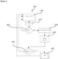
- the method (100) shown in Figure 2 enables the control unit to be active only within predetermined resonance ranges with respect to energy efficiency (102), and to adjust the resonance values of only the adjustable beam (3) by enabling to make the required calculations.
- the control unit cannot be active (sleep mode) (101) outside the predetermined resonance ranges, and thus energy efficiency of the system is enabled to be high.
- the control unit When the determined sleep mode is over, the control unit is waken (102), and the control unit can control the energy amount and voltage values of at least one energy storage device, which is provided in the system and provides sufficient energy for operation of the system.
- control unit can evaluate the amount of energy stored by measuring the voltage values of the capacitor connected to the energy storage device.
- the phase difference between the adjustable beam (3) and the fixed beam (4), and the voltage values of the frequency are measured (104) and then recorded by the control unit for a certain period of time.
- the frequency of the ambient vibration and the phase difference between the output voltages of the adjustable beam (3) and the fixed beam (4) are calculated (105).
- Instantaneous natural frequency ( ⁇ n1) of the adjustable beam (3) can be calculated by the control unit by using the phase difference calculated (105) by the control unit.
- the adjustable beam (3) and the fixed beam (4) are modelled as a linear spring-mass-damping system, and it is considered that the value of the damping ratio of the adjustable beam (3) and the fixed beam (4) is known.
- the control unit After measurement of the natural frequency of the adjustable beam (3), the control unit calculates the difference ( ⁇ - ⁇ n1) between the ambient frequency (co) and the natural frequency of the adjustable beam (3) (105). Then the control unit compares the positive value of the differences between the ambient frequency (co) and the natural frequency of the adjustable beam (3) with a predetermined threshold value (TV) (106). If the difference is smaller than the threshold value, it is accepted that the adjustable beam (3) is in resonant state and it is decided not to operate the piezomotor (5), and the control unit returns to sleep mode (101). If the difference is greater than the threshold value, the piezomotor (5) actuator (107) enables the mass (7) to be brought to the determined position for a predetermined period of time. It is sufficient to look at the sign of the ( ⁇ - ⁇ n1) value in order to determine the movement direction of the mass (7). After this process, the control unit returns to sleep mode (101).
- the energy harvester (1) has the feature of self-locking by means of its method (100), the actuator is enabled not to consume energy in cases where the ambient vibration is in fixed frequency and thus the system is enabled to be operated more efficiently. Furthermore, by means of the method (100) run in the control unit, the energy harvester (1) has high energy production and can be operated with high efficiency independent of amplitude.
Landscapes
- General Electrical Machinery Utilizing Piezoelectricity, Electrostriction Or Magnetostriction (AREA)
- Apparatuses For Generation Of Mechanical Vibrations (AREA)
Claims (1)
- Procédé (100) pour faire fonctionner une unité de commande d'un dispositif de collecteur d'énergie (1), comprenant les étapes consistant à- activer (102) la centrale à partir d'un mode veille (101),- vérifier s'il y a suffisamment d'énergie dans une unité de stockage d'énergie (103),- s'il est détecté qu'il y a suffisamment d'énergie (103), mesurer les valeurs de différence de phase et de fréquence (104) d'un faisceau réglable (3) et d'un faisceau fixe (4),- enregistrer les valeurs de différence de phase et de fréquence mesurées (104) dans la mémoire de l'unité de commande,- calculer la fréquence de la vibration ambiante et la différence de phase entre les tensions de sortie du faisceau réglable (3) et du faisceau fixe (4) en utilisant lesdites valeurs enregistrées (105),- comparer la valeur positive de la différence de phase calculée (105) avec une valeur seuil prédéterminée (TV) (106),- si la différence de phase calculée (105) est inférieure à ladite valeur seuil (TV), la position de la masse (7) est modifiée au moyen d'un piézomoteur (5)(107),- si la différence de phase calculée (105) est supérieure à ladite valeur seuil (TV), la commutation de l'unité de commande en mode veille.
Applications Claiming Priority (2)
| Application Number | Priority Date | Filing Date | Title |
|---|---|---|---|
| TR201505633 | 2015-05-11 | ||
| PCT/TR2016/050138 WO2016182521A1 (fr) | 2015-05-11 | 2016-05-06 | Dispositif de collecte d'énergie de vibration |
Publications (2)
| Publication Number | Publication Date |
|---|---|
| EP3295554A1 EP3295554A1 (fr) | 2018-03-21 |
| EP3295554B1 true EP3295554B1 (fr) | 2019-04-24 |
Family
ID=56131603
Family Applications (1)
| Application Number | Title | Priority Date | Filing Date |
|---|---|---|---|
| EP16729405.7A Active EP3295554B1 (fr) | 2015-05-11 | 2016-05-06 | Dispositif de collecte d'énergie de vibration |
Country Status (3)
| Country | Link |
|---|---|
| EP (1) | EP3295554B1 (fr) |
| TR (1) | TR201909484T4 (fr) |
| WO (1) | WO2016182521A1 (fr) |
Families Citing this family (3)
| Publication number | Priority date | Publication date | Assignee | Title |
|---|---|---|---|---|
| EP3745584B1 (fr) * | 2019-05-27 | 2022-02-09 | Hahn-Schickard-Gesellschaft für angewandte Forschung e.V. | Système de récolte d'énergie cinétique à fréquence propre réglable |
| CN111769757A (zh) * | 2020-05-19 | 2020-10-13 | 中国电子科技集团公司第五十四研究所 | 一种悬臂梁振子固有频率可调的压电发电结构 |
| CN114039506B (zh) * | 2021-11-02 | 2024-02-27 | 上海交通大学 | 自调谐压电能量收集装置 |
Family Cites Families (9)
| Publication number | Priority date | Publication date | Assignee | Title |
|---|---|---|---|---|
| JPH1130628A (ja) * | 1997-07-11 | 1999-02-02 | Matsushita Electric Ind Co Ltd | 加速度センサー用バイモルフ型圧電素子とその製造方法 |
| US7667375B2 (en) | 2006-04-06 | 2010-02-23 | Lockheed Martin Corporation | Broad band energy harvesting system and related methods |
| US8222754B1 (en) | 2008-05-28 | 2012-07-17 | Arjae Spectral Enterprises Ltd. | Vibration-based power generator |
| US8036847B2 (en) * | 2008-09-25 | 2011-10-11 | Rockwell Automation Technologies, Inc. | Maximum information capture from energy constrained sensor nodes |
| DE102008056127A1 (de) | 2008-11-06 | 2010-06-10 | Albert-Ludwigs-Universität Freiburg | Elektromechanischer Energiewandler zur Erzeugung von elektrischer Energie aus mechanischen Bewegungen |
| WO2011041679A2 (fr) | 2009-10-01 | 2011-04-07 | Viking At, Llc | Appareil et procédé de récupération de l'énergie électrique à partir d'un mouvement mécanique |
| EP2610935A1 (fr) * | 2012-01-02 | 2013-07-03 | Stichting IMEC Nederland | Dispositif d'exploitation d'énergie |
| CN103354434A (zh) | 2013-07-02 | 2013-10-16 | 天津大学 | 双稳压电悬臂梁振动能量采集器 |
| CN103986367B (zh) * | 2014-04-28 | 2017-01-11 | 浙江海洋学院 | 压电式能量收集系统 |
-
2016
- 2016-05-06 EP EP16729405.7A patent/EP3295554B1/fr active Active
- 2016-05-06 WO PCT/TR2016/050138 patent/WO2016182521A1/fr not_active Ceased
- 2016-05-06 TR TR2019/09484T patent/TR201909484T4/tr unknown
Non-Patent Citations (1)
| Title |
|---|
| None * |
Also Published As
| Publication number | Publication date |
|---|---|
| WO2016182521A1 (fr) | 2016-11-17 |
| TR201909484T4 (tr) | 2019-07-22 |
| EP3295554A1 (fr) | 2018-03-21 |
Similar Documents
| Publication | Publication Date | Title |
|---|---|---|
| Challa et al. | Towards an autonomous self-tuning vibration energy harvesting device for wireless sensor network applications | |
| Kuang et al. | Design study of a mechanically plucked piezoelectric energy harvester using validated finite element modelling | |
| Zhu et al. | Strategies for increasing the operating frequency range of vibration energy harvesters: a review | |
| Zhou et al. | Exploitation of a tristable nonlinear oscillator for improving broadband vibration energy harvesting | |
| Karadag et al. | A self-sufficient and frequency tunable piezoelectric vibration energy harvester | |
| EP2487732A2 (fr) | Générateur piézoélectrique bistable | |
| EP3295554B1 (fr) | Dispositif de collecte d'énergie de vibration | |
| US20090322184A1 (en) | Energy Harvesting Using Frequency Rectification | |
| Ayala et al. | Autonomous tunable energy harvester | |
| US8970092B2 (en) | Electricity generator having recovery of energy from mechanical vibrations | |
| Ayala-Garcia et al. | A tunable kinetic energy harvester with dynamic over range protection | |
| Fu et al. | Broadband rotational energy harvesting using bistable mechanism and frequency up-conversion | |
| Chen et al. | The design, fabrication and analysis of a cantilever-based tensile-mode nonlinear piezoelectric energy harvester | |
| KR101504867B1 (ko) | 능동형 에너지 수확기 | |
| Basari et al. | Evaluation on mechanical impact parameters in piezoelectric power generation | |
| Trigona et al. | Tri-stable behavior in mechanical oscillators to improve the performance of vibration energy harvesters | |
| Neiss et al. | Tunable nonlinear piezoelectric vibration harvester | |
| Kim et al. | Performance Characteristics of Vibration Energy Harvesting Using [001] and [011]-Poled PMN-PZT Single Crystals | |
| Eichhorn et al. | An energy-autonomous self-tunable piezoelectric vibration energy harvesting system | |
| Moshrefi-Torbati et al. | Adaptive inertia tuning of an energy harvester for increasing its operational bandwidth | |
| Roy et al. | Tuning non-linearity in cascaded tapered spring topologies of electromagnetic-vibrational energy harvesters with enhanced figure of merit | |
| Panthongsy et al. | A test bench for characterization of piezoelectric frequency up-converting energy harvesters | |
| Wu et al. | Broadband energy harvesting using nonlinear 2-DOF configuration | |
| Chen et al. | Systematic study of dual resonant rectilinear-to-rotary motion converter for low frequency vibrational energy harvesting | |
| Tahir et al. | Performance measurement of piezoelectric energy harvester with permanent magnet assembly for wearable devices |
Legal Events
| Date | Code | Title | Description |
|---|---|---|---|
| STAA | Information on the status of an ep patent application or granted ep patent |
Free format text: STATUS: THE INTERNATIONAL PUBLICATION HAS BEEN MADE |
|
| PUAI | Public reference made under article 153(3) epc to a published international application that has entered the european phase |
Free format text: ORIGINAL CODE: 0009012 |
|
| STAA | Information on the status of an ep patent application or granted ep patent |
Free format text: STATUS: REQUEST FOR EXAMINATION WAS MADE |
|
| 17P | Request for examination filed |
Effective date: 20171025 |
|
| AK | Designated contracting states |
Kind code of ref document: A1 Designated state(s): AL AT BE BG CH CY CZ DE DK EE ES FI FR GB GR HR HU IE IS IT LI LT LU LV MC MK MT NL NO PL PT RO RS SE SI SK SM TR |
|
| AX | Request for extension of the european patent |
Extension state: BA ME |
|
| DAV | Request for validation of the european patent (deleted) | ||
| DAX | Request for extension of the european patent (deleted) | ||
| GRAP | Despatch of communication of intention to grant a patent |
Free format text: ORIGINAL CODE: EPIDOSNIGR1 |
|
| STAA | Information on the status of an ep patent application or granted ep patent |
Free format text: STATUS: GRANT OF PATENT IS INTENDED |
|
| INTG | Intention to grant announced |
Effective date: 20181214 |
|
| GRAS | Grant fee paid |
Free format text: ORIGINAL CODE: EPIDOSNIGR3 |
|
| GRAA | (expected) grant |
Free format text: ORIGINAL CODE: 0009210 |
|
| STAA | Information on the status of an ep patent application or granted ep patent |
Free format text: STATUS: THE PATENT HAS BEEN GRANTED |
|
| AK | Designated contracting states |
Kind code of ref document: B1 Designated state(s): AL AT BE BG CH CY CZ DE DK EE ES FI FR GB GR HR HU IE IS IT LI LT LU LV MC MK MT NL NO PL PT RO RS SE SI SK SM TR |
|
| REG | Reference to a national code |
Ref country code: GB Ref legal event code: FG4D |
|
| REG | Reference to a national code |
Ref country code: CH Ref legal event code: EP |
|
| REG | Reference to a national code |
Ref country code: AT Ref legal event code: REF Ref document number: 1125322 Country of ref document: AT Kind code of ref document: T Effective date: 20190515 Ref country code: IE Ref legal event code: FG4D |
|
| REG | Reference to a national code |
Ref country code: DE Ref legal event code: R096 Ref document number: 602016012897 Country of ref document: DE |
|
| REG | Reference to a national code |
Ref country code: NL Ref legal event code: MP Effective date: 20190424 |
|
| REG | Reference to a national code |
Ref country code: LT Ref legal event code: MG4D |
|
| PG25 | Lapsed in a contracting state [announced via postgrant information from national office to epo] |
Ref country code: NL Free format text: LAPSE BECAUSE OF FAILURE TO SUBMIT A TRANSLATION OF THE DESCRIPTION OR TO PAY THE FEE WITHIN THE PRESCRIBED TIME-LIMIT Effective date: 20190424 |
|
| PG25 | Lapsed in a contracting state [announced via postgrant information from national office to epo] |
Ref country code: AL Free format text: LAPSE BECAUSE OF FAILURE TO SUBMIT A TRANSLATION OF THE DESCRIPTION OR TO PAY THE FEE WITHIN THE PRESCRIBED TIME-LIMIT Effective date: 20190424 Ref country code: PT Free format text: LAPSE BECAUSE OF FAILURE TO SUBMIT A TRANSLATION OF THE DESCRIPTION OR TO PAY THE FEE WITHIN THE PRESCRIBED TIME-LIMIT Effective date: 20190824 Ref country code: LT Free format text: LAPSE BECAUSE OF FAILURE TO SUBMIT A TRANSLATION OF THE DESCRIPTION OR TO PAY THE FEE WITHIN THE PRESCRIBED TIME-LIMIT Effective date: 20190424 Ref country code: ES Free format text: LAPSE BECAUSE OF FAILURE TO SUBMIT A TRANSLATION OF THE DESCRIPTION OR TO PAY THE FEE WITHIN THE PRESCRIBED TIME-LIMIT Effective date: 20190424 Ref country code: HR Free format text: LAPSE BECAUSE OF FAILURE TO SUBMIT A TRANSLATION OF THE DESCRIPTION OR TO PAY THE FEE WITHIN THE PRESCRIBED TIME-LIMIT Effective date: 20190424 Ref country code: NO Free format text: LAPSE BECAUSE OF FAILURE TO SUBMIT A TRANSLATION OF THE DESCRIPTION OR TO PAY THE FEE WITHIN THE PRESCRIBED TIME-LIMIT Effective date: 20190724 Ref country code: SE Free format text: LAPSE BECAUSE OF FAILURE TO SUBMIT A TRANSLATION OF THE DESCRIPTION OR TO PAY THE FEE WITHIN THE PRESCRIBED TIME-LIMIT Effective date: 20190424 Ref country code: FI Free format text: LAPSE BECAUSE OF FAILURE TO SUBMIT A TRANSLATION OF THE DESCRIPTION OR TO PAY THE FEE WITHIN THE PRESCRIBED TIME-LIMIT Effective date: 20190424 |
|
| PG25 | Lapsed in a contracting state [announced via postgrant information from national office to epo] |
Ref country code: PL Free format text: LAPSE BECAUSE OF FAILURE TO SUBMIT A TRANSLATION OF THE DESCRIPTION OR TO PAY THE FEE WITHIN THE PRESCRIBED TIME-LIMIT Effective date: 20190424 Ref country code: RS Free format text: LAPSE BECAUSE OF FAILURE TO SUBMIT A TRANSLATION OF THE DESCRIPTION OR TO PAY THE FEE WITHIN THE PRESCRIBED TIME-LIMIT Effective date: 20190424 Ref country code: GR Free format text: LAPSE BECAUSE OF FAILURE TO SUBMIT A TRANSLATION OF THE DESCRIPTION OR TO PAY THE FEE WITHIN THE PRESCRIBED TIME-LIMIT Effective date: 20190725 Ref country code: LV Free format text: LAPSE BECAUSE OF FAILURE TO SUBMIT A TRANSLATION OF THE DESCRIPTION OR TO PAY THE FEE WITHIN THE PRESCRIBED TIME-LIMIT Effective date: 20190424 Ref country code: BG Free format text: LAPSE BECAUSE OF FAILURE TO SUBMIT A TRANSLATION OF THE DESCRIPTION OR TO PAY THE FEE WITHIN THE PRESCRIBED TIME-LIMIT Effective date: 20190724 |
|
| REG | Reference to a national code |
Ref country code: AT Ref legal event code: MK05 Ref document number: 1125322 Country of ref document: AT Kind code of ref document: T Effective date: 20190424 |
|
| REG | Reference to a national code |
Ref country code: CH Ref legal event code: PL |
|
| PG25 | Lapsed in a contracting state [announced via postgrant information from national office to epo] |
Ref country code: IS Free format text: LAPSE BECAUSE OF FAILURE TO SUBMIT A TRANSLATION OF THE DESCRIPTION OR TO PAY THE FEE WITHIN THE PRESCRIBED TIME-LIMIT Effective date: 20190824 |
|
| REG | Reference to a national code |
Ref country code: DE Ref legal event code: R097 Ref document number: 602016012897 Country of ref document: DE |
|
| PG25 | Lapsed in a contracting state [announced via postgrant information from national office to epo] |
Ref country code: MC Free format text: LAPSE BECAUSE OF FAILURE TO SUBMIT A TRANSLATION OF THE DESCRIPTION OR TO PAY THE FEE WITHIN THE PRESCRIBED TIME-LIMIT Effective date: 20190424 Ref country code: CH Free format text: LAPSE BECAUSE OF NON-PAYMENT OF DUE FEES Effective date: 20190531 Ref country code: LI Free format text: LAPSE BECAUSE OF NON-PAYMENT OF DUE FEES Effective date: 20190531 Ref country code: SK Free format text: LAPSE BECAUSE OF FAILURE TO SUBMIT A TRANSLATION OF THE DESCRIPTION OR TO PAY THE FEE WITHIN THE PRESCRIBED TIME-LIMIT Effective date: 20190424 Ref country code: RO Free format text: LAPSE BECAUSE OF FAILURE TO SUBMIT A TRANSLATION OF THE DESCRIPTION OR TO PAY THE FEE WITHIN THE PRESCRIBED TIME-LIMIT Effective date: 20190424 Ref country code: CZ Free format text: LAPSE BECAUSE OF FAILURE TO SUBMIT A TRANSLATION OF THE DESCRIPTION OR TO PAY THE FEE WITHIN THE PRESCRIBED TIME-LIMIT Effective date: 20190424 Ref country code: DK Free format text: LAPSE BECAUSE OF FAILURE TO SUBMIT A TRANSLATION OF THE DESCRIPTION OR TO PAY THE FEE WITHIN THE PRESCRIBED TIME-LIMIT Effective date: 20190424 Ref country code: EE Free format text: LAPSE BECAUSE OF FAILURE TO SUBMIT A TRANSLATION OF THE DESCRIPTION OR TO PAY THE FEE WITHIN THE PRESCRIBED TIME-LIMIT Effective date: 20190424 Ref country code: AT Free format text: LAPSE BECAUSE OF FAILURE TO SUBMIT A TRANSLATION OF THE DESCRIPTION OR TO PAY THE FEE WITHIN THE PRESCRIBED TIME-LIMIT Effective date: 20190424 |
|
| REG | Reference to a national code |
Ref country code: BE Ref legal event code: MM Effective date: 20190531 |
|
| PG25 | Lapsed in a contracting state [announced via postgrant information from national office to epo] |
Ref country code: SM Free format text: LAPSE BECAUSE OF FAILURE TO SUBMIT A TRANSLATION OF THE DESCRIPTION OR TO PAY THE FEE WITHIN THE PRESCRIBED TIME-LIMIT Effective date: 20190424 Ref country code: LU Free format text: LAPSE BECAUSE OF NON-PAYMENT OF DUE FEES Effective date: 20190506 Ref country code: IT Free format text: LAPSE BECAUSE OF FAILURE TO SUBMIT A TRANSLATION OF THE DESCRIPTION OR TO PAY THE FEE WITHIN THE PRESCRIBED TIME-LIMIT Effective date: 20190424 |
|
| PLBE | No opposition filed within time limit |
Free format text: ORIGINAL CODE: 0009261 |
|
| STAA | Information on the status of an ep patent application or granted ep patent |
Free format text: STATUS: NO OPPOSITION FILED WITHIN TIME LIMIT |
|
| 26N | No opposition filed |
Effective date: 20200127 |
|
| PG25 | Lapsed in a contracting state [announced via postgrant information from national office to epo] |
Ref country code: IE Free format text: LAPSE BECAUSE OF NON-PAYMENT OF DUE FEES Effective date: 20190506 |
|
| PG25 | Lapsed in a contracting state [announced via postgrant information from national office to epo] |
Ref country code: BE Free format text: LAPSE BECAUSE OF NON-PAYMENT OF DUE FEES Effective date: 20190531 Ref country code: SI Free format text: LAPSE BECAUSE OF FAILURE TO SUBMIT A TRANSLATION OF THE DESCRIPTION OR TO PAY THE FEE WITHIN THE PRESCRIBED TIME-LIMIT Effective date: 20190424 |
|
| PG25 | Lapsed in a contracting state [announced via postgrant information from national office to epo] |
Ref country code: FR Free format text: LAPSE BECAUSE OF NON-PAYMENT OF DUE FEES Effective date: 20190624 |
|
| PG25 | Lapsed in a contracting state [announced via postgrant information from national office to epo] |
Ref country code: CY Free format text: LAPSE BECAUSE OF FAILURE TO SUBMIT A TRANSLATION OF THE DESCRIPTION OR TO PAY THE FEE WITHIN THE PRESCRIBED TIME-LIMIT Effective date: 20190424 |
|
| PG25 | Lapsed in a contracting state [announced via postgrant information from national office to epo] |
Ref country code: MT Free format text: LAPSE BECAUSE OF FAILURE TO SUBMIT A TRANSLATION OF THE DESCRIPTION OR TO PAY THE FEE WITHIN THE PRESCRIBED TIME-LIMIT Effective date: 20190424 Ref country code: HU Free format text: LAPSE BECAUSE OF FAILURE TO SUBMIT A TRANSLATION OF THE DESCRIPTION OR TO PAY THE FEE WITHIN THE PRESCRIBED TIME-LIMIT; INVALID AB INITIO Effective date: 20160506 |
|
| PG25 | Lapsed in a contracting state [announced via postgrant information from national office to epo] |
Ref country code: MK Free format text: LAPSE BECAUSE OF FAILURE TO SUBMIT A TRANSLATION OF THE DESCRIPTION OR TO PAY THE FEE WITHIN THE PRESCRIBED TIME-LIMIT Effective date: 20190424 |
|
| PGFP | Annual fee paid to national office [announced via postgrant information from national office to epo] |
Ref country code: TR Payment date: 20250416 Year of fee payment: 10 |
|
| PGFP | Annual fee paid to national office [announced via postgrant information from national office to epo] |
Ref country code: DE Payment date: 20250722 Year of fee payment: 10 |
|
| PGFP | Annual fee paid to national office [announced via postgrant information from national office to epo] |
Ref country code: GB Payment date: 20250717 Year of fee payment: 10 |