EP3295580B1 - Signaux de référence, mesures, et architectures et procédés de démodulation - Google Patents
Signaux de référence, mesures, et architectures et procédés de démodulation Download PDFInfo
- Publication number
- EP3295580B1 EP3295580B1 EP15832839.3A EP15832839A EP3295580B1 EP 3295580 B1 EP3295580 B1 EP 3295580B1 EP 15832839 A EP15832839 A EP 15832839A EP 3295580 B1 EP3295580 B1 EP 3295580B1
- Authority
- EP
- European Patent Office
- Prior art keywords
- reference signals
- circuitry
- architecture
- signals
- analog
- Prior art date
- Legal status (The legal status is an assumption and is not a legal conclusion. Google has not performed a legal analysis and makes no representation as to the accuracy of the status listed.)
- Active
Links
Images


Classifications
-
- H—ELECTRICITY
- H04—ELECTRIC COMMUNICATION TECHNIQUE
- H04B—TRANSMISSION
- H04B7/00—Radio transmission systems, i.e. using radiation field
- H04B7/02—Diversity systems; Multi-antenna system, i.e. transmission or reception using multiple antennas
- H04B7/04—Diversity systems; Multi-antenna system, i.e. transmission or reception using multiple antennas using two or more spaced independent antennas
- H04B7/0408—Diversity systems; Multi-antenna system, i.e. transmission or reception using multiple antennas using two or more spaced independent antennas using two or more beams, i.e. beam diversity
-
- H—ELECTRICITY
- H04—ELECTRIC COMMUNICATION TECHNIQUE
- H04B—TRANSMISSION
- H04B7/00—Radio transmission systems, i.e. using radiation field
- H04B7/02—Diversity systems; Multi-antenna system, i.e. transmission or reception using multiple antennas
- H04B7/04—Diversity systems; Multi-antenna system, i.e. transmission or reception using multiple antennas using two or more spaced independent antennas
- H04B7/06—Diversity systems; Multi-antenna system, i.e. transmission or reception using multiple antennas using two or more spaced independent antennas at the transmitting station
- H04B7/0613—Diversity systems; Multi-antenna system, i.e. transmission or reception using multiple antennas using two or more spaced independent antennas at the transmitting station using simultaneous transmission
- H04B7/0615—Diversity systems; Multi-antenna system, i.e. transmission or reception using multiple antennas using two or more spaced independent antennas at the transmitting station using simultaneous transmission of weighted versions of same signal
- H04B7/0617—Diversity systems; Multi-antenna system, i.e. transmission or reception using multiple antennas using two or more spaced independent antennas at the transmitting station using simultaneous transmission of weighted versions of same signal for beam forming
-
- H—ELECTRICITY
- H04—ELECTRIC COMMUNICATION TECHNIQUE
- H04B—TRANSMISSION
- H04B7/00—Radio transmission systems, i.e. using radiation field
- H04B7/02—Diversity systems; Multi-antenna system, i.e. transmission or reception using multiple antennas
- H04B7/04—Diversity systems; Multi-antenna system, i.e. transmission or reception using multiple antennas using two or more spaced independent antennas
- H04B7/06—Diversity systems; Multi-antenna system, i.e. transmission or reception using multiple antennas using two or more spaced independent antennas at the transmitting station
- H04B7/0686—Hybrid systems, i.e. switching and simultaneous transmission
- H04B7/0695—Hybrid systems, i.e. switching and simultaneous transmission using beam selection
- H04B7/06952—Selecting one or more beams from a plurality of beams, e.g. beam training, management or sweeping
-
- H—ELECTRICITY
- H04—ELECTRIC COMMUNICATION TECHNIQUE
- H04B—TRANSMISSION
- H04B7/00—Radio transmission systems, i.e. using radiation field
- H04B7/02—Diversity systems; Multi-antenna system, i.e. transmission or reception using multiple antennas
- H04B7/04—Diversity systems; Multi-antenna system, i.e. transmission or reception using multiple antennas using two or more spaced independent antennas
- H04B7/08—Diversity systems; Multi-antenna system, i.e. transmission or reception using multiple antennas using two or more spaced independent antennas at the receiving station
- H04B7/0837—Diversity systems; Multi-antenna system, i.e. transmission or reception using multiple antennas using two or more spaced independent antennas at the receiving station using pre-detection combining
- H04B7/0842—Weighted combining
- H04B7/086—Weighted combining using weights depending on external parameters, e.g. direction of arrival [DOA], predetermined weights or beamforming
-
- H—ELECTRICITY
- H04—ELECTRIC COMMUNICATION TECHNIQUE
- H04B—TRANSMISSION
- H04B7/00—Radio transmission systems, i.e. using radiation field
- H04B7/02—Diversity systems; Multi-antenna system, i.e. transmission or reception using multiple antennas
- H04B7/04—Diversity systems; Multi-antenna system, i.e. transmission or reception using multiple antennas using two or more spaced independent antennas
- H04B7/08—Diversity systems; Multi-antenna system, i.e. transmission or reception using multiple antennas using two or more spaced independent antennas at the receiving station
- H04B7/0868—Hybrid systems, i.e. switching and combining
- H04B7/088—Hybrid systems, i.e. switching and combining using beam selection
-
- H—ELECTRICITY
- H04—ELECTRIC COMMUNICATION TECHNIQUE
- H04W—WIRELESS COMMUNICATION NETWORKS
- H04W72/00—Local resource management
- H04W72/04—Wireless resource allocation
- H04W72/044—Wireless resource allocation based on the type of the allocated resource
- H04W72/0446—Resources in time domain, e.g. slots or frames
-
- H—ELECTRICITY
- H04—ELECTRIC COMMUNICATION TECHNIQUE
- H04W—WIRELESS COMMUNICATION NETWORKS
- H04W72/00—Local resource management
- H04W72/30—Resource management for broadcast services
Definitions
- the present disclosure relates to mobile wireless communication and reference signals used for communication.
- Beamforming is a technique used in mobile communications, including telecommunications, to enhance communication and performance. Beamforming involves combining elements so that signals at some angles experience constructive interference while others experience destructive interference. Beamforming can be used at transmitting and/or receiving ends in order to achieve spatial selectivity. The improvement compared with omni-directional transmitting and receiving is referred to as a transmit/receive beamforming gain or loss.
- Various beamforming techniques can be used, such as analog, digital, or hybrid (combination of analog and digital).
- the specific technique used can vary according to complexity, power consumption, beamforming coverage and beamforming gain.
- a component can be a processor (e.g., a microprocessor, a controller, or other processing device), a process running on a processor, a controller, an object, an executable, a program, a storage device, a computer, a tablet PC, an electronic circuit and/or a mobile phone with a processing device.
- a processor e.g., a microprocessor, a controller, or other processing device
- an application running on a server and the server can also be a component.
- One or more components can reside within a process, and a component can be localized on one computer and/or distributed between two or more computers.
- a set of elements or a set of other components can be described herein, in which the term "set" can be interpreted as "one or more.”
- these components can execute from various computer readable storage media having various data structures stored thereon such as with a module, for example.
- the components can communicate via local and/or remote processes such as in accordance with a signal having one or more data packets (e.g., data from one component interacting with another component in a local system, distributed system, and/or across a network, such as, the Internet, a local area network, a wide area network, or similar network with other systems via the signal).
- a signal having one or more data packets (e.g., data from one component interacting with another component in a local system, distributed system, and/or across a network, such as, the Internet, a local area network, a wide area network, or similar network with other systems via the signal).
- a component can be an apparatus with specific functionality provided by mechanical parts operated by electric or electronic circuitry, in which the electric or electronic circuitry can be operated by a software application or a firmware application executed by one or more processors.
- the one or more processors can be internal or external to the apparatus and can execute at least a part of the software or firmware application.
- a component can be an apparatus that provides specific functionality through electronic components without mechanical parts; the electronic components can include one or more processors therein to execute software and/or firmware that confer(s), at least in part, the functionality of the electronic components.
- circuitry may refer to, be part of, or include an Application Specific Integrated Circuit (ASIC), an electronic circuit, a processor (shared, dedicated, or group), and/or memory (shared, dedicated, or group) that execute one or more software or firmware programs, a combinational logic circuit, and/or other suitable hardware components that provide the described functionality.
- ASIC Application Specific Integrated Circuit
- the circuitry may be implemented in, or functions associated with the circuitry may be implemented by, one or more software or firmware modules.
- circuitry may include logic, at least partially operable in hardware.
- Beamforming is a signal processing technique that can be used in a communications array for directional signal transmission or reception. Components of a phased array are combined in such a way that signals at particular angles experience constructive interference while others experience destructive interference. Beamforming can be used at both the transmitting and receiving ends in order to achieve spatial selectivity. Compared to omni-directional reception/ transmission the amount of improvement in signal strength is in the transmit/receive beamforming gain (or loss). Large bandwidths available at millimeter wave frequencies for communication systems can further be used to combat the exponential rise in the demand for data traffic. At millimeter wave frequencies, massive antenna arrays can be used to beamform communication signals in a particular direction in order to mitigate the effects of increased path loss. Beamforming can be applied either in the digital domain or analog radio frequency (RF) domain.
- RF radio frequency
- the beamforming architectures use and/or determine various information or communication metrics to facilitate communication.
- the communication metrics include channel state information (CSI) and radio resource management (RRM) measurements, achievable multi-input multi-output (MIMO) beamforming gains, coverage, and the like.
- the determination of the communication metrics is performed by taking into account system overhead and latency.
- the communication metrics are applicable to frequency division duplexing (FDD) systems and time division duplexing (TDD) systems that employ different antenna schemes for a transmitter and a receiver, or utilize un-calibrated antennas. Additionally, analog beamforming architectures with a limited number of receiver chains rely on using repeated reference signals to determine beamforming weights at the receiver.
- the present disclosure includes various aspects/embodiments that facilitate beamforming communication architectures.
- the aspects and embodiments include a downlink reference signal design and use for receiver analog beamforming and demodulation. Additionally, CSI measurements and mobility measurements in high frequency band radio access technology (HFB RAT) based cellular network can be obtained.
- HFB RAT high frequency band radio access technology
- Fig. 1 is a diagram illustrating a beamforming architecture 100 according to various aspects or embodiments.
- the architecture 100 incorporates a downlink reference signal design that facilitates beamforming, demodulation, CSI measurements, mobility measurements in HFB RAT based cellular networks and the like.
- the architecture 100 can be included in one or more base stations or eNodeBs.
- the architecture includes a control component 102, a plurality of transmission units (TXU) 104 and a communications array.
- the beamforming architecture 100 is associated with a cell or small cell and transmits analog beamformed cell-specific reference signals (AB-CRS) in subframes.
- AB-CRS analog beamformed cell-specific reference signals
- One or more reference-signal sequences used to generate the AB-CRS are determined based on a cell identity (ID) or combination of cell ID, beam ID, and other network entity IDs such as transmission point (TP) ID, and the determined one or more sequences are beamformed with analog beams.
- the AB-CRS can be provided in every subframe, pre-determined subframes, a set of semi-statically configured subframes and variations thereof.
- the control component 102 can include one or more processors and a data store.
- the control component 102 can operate to process received or input signals by one or more pre-coders, encoders, decoders or other communication components for receiving or transmitting communication data.
- the control component 102 can, for example, receive a diversity of data signals from different carriers, such as RF signals in a broadband frequency range.
- the control component 102 can process received signals as millimeter wave signals for transmission in 5G or other wireless transmission in a system having phased array beam forming operations.
- the beamforming architecture 100 is analog, however variations are contemplated that are hybrid of analog and digital, or digital.
- the control component 102 is configured to generate subframes 112 of a frame.
- the subframes 112 can include reference signals, analog beamformed cell-specific reference signals (AB-CRS).
- the subframes 112 are associated with one of the plurality of transmission units 104 or logical ports.
- the transmission units 104 are also referred to as an AB-CRS port. Additional detail on the generation of the AB-CRS and the reference subframes 112 are provided infra.
- a frame includes a number of the subframes 112, each subframe includes symbols and a portion of the symbols of each subframe can include the AB-CRS.
- a frame includes ten subframes and each subframe includes 14 orthogononal frequency division multiplexing (OFDM)/single carrier-frequency division multiple access (SC-FDMA) symbols, and one or more of the symbols carry AB-CRS.
- a frame can include a master information block.
- the transmission units 104 are processing chains that are mapped to the communication array 106, which associates the transmission units 104 with an antenna of an antenna array 108.
- the number of transmission units 104 can vary, in one example there are 4, in another example there are 8, in yet another example there are more than 4.
- the transmission units 104 generate a plurality of signals 114 for transmission. It is appreciated that the transmission units 104 can also be configured as receiver chains for receiving and processing received signals from the communication array 106.
- the transmission units 104 include phase shifting components configured to phase shift the subframes 112 and other inputs according to selected beamshaping characteristics.
- the AB-CRS can be multiplexed into an orthogonal frequency division multiplexing (OFDM) symbol, single carrier frequency division multiple access (SC-FDMA) symbol and the like. Additionally, the AB-CRS are separated from physical downlink shared channel (PDSCH) transmission in the time domain.
- OFDM orthogonal frequency division multiplexing
- SC-FDMA single carrier frequency division multiple access
- PDSCH physical downlink shared channel
- the communication array 106 is configured to operate as a beam forming device, such as an analog beam forming device.
- the communication array 106 receives the signals 114 and applies the selected beamforming characteristics and provides signals for transmission to the antenna array 108.
- the selected beamforming characteristics include selected angles or vectors in space or air and power levels.
- the communication array 106 can include power amplifiers that have different levels of output powers for transmission.
- a user equipment device 110 or devices can receive the transmitted signals.
- the user equipment device 110 utilizes the AB-CRS in order to determine communication metrics including, but not limited to CSI, radio resource management (RRM) measurements and the like. Additionally, the AB-CRS is used to generate beamforming weights at the receiving end.
- the beamforming architecture 100 uses analog beam diversity along with channel coding and interleaving to transmit and/or receive physical channels conveying small size control information, such as physical control format indicator channel (PCFICH), physical hybrid ARQ indicator channel (PHICH), physical downlink control channel (PDCCH), physical broadcast channel (PBCH) and the like, including those intended for multiple UEs. Additionally, the AB-CRS are time-frequency multiplexed with the physical channels carrying control information. This allows the UEs, including the UE 110, to perform receiver analog beam tracking and control channel demodulation concurrently and to utilize radio resources more efficiently.
- PCFICH physical control format indicator channel
- PHICH physical hybrid ARQ indicator channel
- PDCH physical downlink control channel
- PBCH physical broadcast channel
- Fig. 2 is a diagram illustrating a receiver beamforming architecture 200 in accordance with various aspects or embodiments.
- the architecture 200 can be employed in user equipment (UE), mobile devices, and the like.
- UE user equipment
- the receiver beamforming architecture 200 includes a receiver communication array 206, a plurality of receiver chains (RX) 204 and a receiver control component 202.
- the receiver communication array 206 receives a plurality of signals via antennas 208.
- the receiver communication array 206 processes the received signals and provides processed signals 214 to the receiver chains 204.
- the receiver chains 204 provide receiver chain signals 212 to the receiver control component 202.
- the receiver control component 202 obtains a plurality of AB-CRS from the receiver chain signals 212.
- the AB-CRS are used by the UE to perform channel estimation and estimate channel conditions.
- the AB-CRS are decoded by the control component 202, and in one example, the decoded AB-CRS are used to find a master information block (MIB).
- MIB includes parameters needed by the UE for initial access to a cell.
- the receiver control component 202 uses the decoded AB-CRS to determine communication metrics including channel state information (CSI) and radio resource management (RRM) measurements, achievable multi-input multi-output (MIMO) beamforming gains, coverage, and the like.
- the determination of the communication metrics is performed by taking into account system overhead and latency.
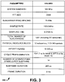
- Fig. 3 is a diagram illustrating example physical layer system parameters 300 for a reference signal for a frame in accordance with various aspects or embodiments.
- the system parameters 300 are for a high frequency band radio access technology (HFB RAT) based cellular network.
- the system parameters 300 are examples of information that can be provided in the frame. It is appreciated that various aspects can use other suitable parameters in frames.
- a small cell eNodeB is assumed to manage multiple beams simultaneously with multiple RF or TXU chains, for example 8.
- frequency selective scheduling and frequency selective (e.g., per subband) beamforming and/or precoding similar to current LTE-A can be supported without restriction.
- the frame includes 10 subframes in this example. Each subframe includes 14 OFDM/SC-FDMA symbols. Within the subframe, a few symbols can be used to carry AB-CRS.
- the frame duration is 2 ms.
- Fig. 4 is a graph depicting an example of predefined azimuth analog beam patterns that are generated by 8x8 uniform planar array antennas, cover one eNodeB sector (120 degrees), and are mapped to 8 AB-CRS ports.
- Each TXU or RF chain at an eNodeB derives one beam pattern, which maps to each AB-CRS port.
- AB-CRS of a given AB-CRS port are beamformed signals with a beam pattern mapped to the AB-CRS port.
- mapping of beam patterns to AB-CRS ports is fixed on subframes where a UE is configured to perform measurement, and dynamic mapping of beam patterns to AB-CRS ports is assumed for other subframes.
- the predefined beam patterns can be used only for measurement and transmission of small size information, such as control information.
- User plane data transmission via PDSCH or dedicated physical control channels may employ other beamforming techniques, such as eigen-beamforming and the advanced beamforming weights can be mapped to demodulation reference signals (DM RS).
- DM RS demodulation reference signals
- Figs. 5A and 5B illustrate an example AB-CRS structure in terms of time-frequency radio resources in accordance with various aspects or embodiments.
- the AB-CRS are transmitted on symbols 0, 1 and 2 and the PDSCH region starts at symbol 3 or later (not shown).
- 3 symbols of a subframe are used to carry AB-CRS.
- a control region can also be present on symbols 0, 1, and 2, or utilize one or more symbols starting with the symbol 3.
- a RE is a minimum resource unit in LTE, indicated by one OFDM/SC-FDMA symbol in time domain and one subcarrier in frequency domain.
- 400 REs are used for 8 AB-CRS ports, which is a lower overhead than LTE cell-specific reference signals' (CRS) overhead, which uses 800 REs for 1 CRS port.
- CRS cell-specific reference signals'
- Fig. 5A depicts an example of the AB-CRS structure 500 according to time and frequency. Symbols 0-2 are shown along a time axis and subbands 0-2 are shown along a frequency axis. Additional symbols can be present for control regions, a PDSCH region and the like but are not shown for illustrative purposes. Additional subbands, for example 2-16, can be present along the frequency axis.
- Fig. 5B depicts an example pattern 501 for a particular cell group.
- the pattern 501 is for the AB-CRS REs for the cell group C.
- the example pattern 501 is shown with 8 AB-CRS ports, numbered 1-8 and 4 subcarriers.
- the pattern 501 is based on 12 subcarriers.
- the pattern 501 is based on one symbol duration.
- a frequency distance between two adjacent AB-CRS subcarriers for a given AB-CRS port is set to be 1.8 MHz (24 subcarrier spacings).
- Fig. 6 is a graph 600 illustrating an example of a cumulative density function (CDF) of root means squared (RMS) delay spread of 28 GHz channels in a dense urban scenario.
- CDF cumulative density function
- RMS root means squared
- the graph 600 depicts time in nano seconds along an x-axis and CDF along a y-axis. Three lines are shown for comparison. Line 603 is an example using hybrid beamforming, line 602 is an example using analog beamforming and line 601 is omni directional.
- the graph 600 shows that transmission (TX) analog beamforming 602 results in a 90 percentile RMS delay spread of 9 nano seconds. Including other scenarios, effective RMS delay spread for other analog beamformed channels is expected to be 40 nano seconds or less. Thus, 50 percent coherence bandwidth is about 5 MHz or larger.
- UE can obtain, from AB-CRS, channel information to demodulate control channels, which are analog beamformed and time frequency multiplexed with AB-CRS.
- adjacent small cells can be categorized as different cell groups for AB-CRS for RE mapping, such as according to a cell ID as in Fig. 5A , and use different AB-CRS REs as shown in Figs. 5A and 5B .
- a first use case involves UE beam acquisition that is made during a cell search phase via receive beam scanning and/or using 2 or more UE RF chains.
- the beam acquisition involves finding one or more optimal sectors among 3-8 UE RX sectors.
- the receiving architecture such as the architecture 200, obtains AB-CRS and uses the AB-CRS to find a finer granularity of optimal or improved analog beams at the UE.
- the UE can acquire coarse and fine beam directions sequentially after measuring AB-CRS for a few subframes, assuming AB-CRS are transmitted in every subframe.
- the UE applies a different Rx analog beam pattern to receive each symbol of symbols 0-2 as shown in Fig. 5A .
- the AB-CRS are directionally transmitted broadcast signals, thus they can be used by multiple UEs. Individual UEs or types of UEs can determine how often to perform measurements for beam acquisition or beam tracking.
- the UE types include, for example, smart phones, tablets, game consoles and the like.
- a second use case involves utilizing AB-CRS for a UE's RRM measurement, based on which a serving small cell or an anchor small cell (for multi-cell coordinated transmission and reception) is determined. It is assumed that an associated eNodeB's coverage includes beam patterns which are mapped to all configured AB-CRS ports of AB-CRS subframes configured for RRM measurement.
- the UE can measure reference signal received power (RSRP) for each AB-CRS port and compute an aggregated RSRP.
- RSRP reference signal received power
- the measurement accuracy typically outperforms the case of measuring wide-beam reference signals.
- the aggregated RSRP takes into account received signal power from all TX directions, without requiring separate transmission of wide-beam based reference signals for RRM measurement.
- a third use case involves using AB-CRS to determine downlink CSI measurements.
- a UE can measure TX and Rx analog beamformed channels for each TX and Rx analog beam-pair. Based on those measurements, the UE can estimate an optimal or improved baseband eNodeB precoding matrix to combine analog beams, an optimal number of spatial layers (rank), and an optimal modulation and coding scheme (MCS).
- An LTE CSI reporting framework such as channel quality indicator (CQI), precoding matrix indicator (PMI), and rank indicator (RI) reporting can be reused.
- CQI channel quality indicator
- PMI precoding matrix indicator
- RI rank indicator
- the UE may report a few AB-CRS port indices whose per-port RSRP are higher than a configured threshold, in order to provide additional information for multi-user MIMO scheduling. If multi-cell/multi-site coordinated transmission and reception are employed, the UE can be configured for measuring and reporting per-port RSRP (or per-port CQI) for multiple configured cells.
- a fourth use case provides an example of demodulation of control channels with TX/RX analog beam diversity.
- Common control channels intended for multiple UEs in a cell may need to be transmitted via all analog beams assigned to AB-CRS ports, in order to reach all UEs within an intended coverage.
- the concept of an LTE physical downlink control channel (PDCCH) "search space", a set of possible PDCCH locations, can be employed.
- PDCH physical downlink control channel
- search space a separate common search space for each TX analog beam can be defined, and a UE is supposed to check one or more common search spaces for one or more optimal TX analog beams.
- the UE can determine one or more optimal TX analog beams by comparing measurements of different AB-CRS ports, and also obtain channel estimates for demodulation from AB-CRS.
- a PDCCH location consists of resource elements (REs) spanned over symbols configured for AB-CRS transmission. This ensures that UE can exploit Rx analog beam diversity to decode PDCCH.
- REs resource elements
- PCFICH physical control format indicator channel
- a fixed set of resource elements which span over a wide frequency band (e.g. with a distributed subcarrier allocation) and AB-CRS symbols, can be configured for PCFICH transmission with each TX analog beam.
- the UE decodes analog beamformed PCFICH corresponding to its optimal TX analog beam. Again, the optimal TX analog beam can be determined by measurements of AB-CRS.
- PHICH physical hybrid ARQ indicator channel
- AB-CRS can be used for demodulation of PHICH.
- TX analog beam used for PHICH transmission is for an eNodeB to use a latest reported analog PMI for PHICH beamforming.
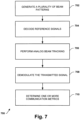
- Fig. 7 is a flow diagram illustrating a method 700 of using analog beamformed cell-specific reference signals in accordance with various aspects or embodiments.
- the method 700 receives and decodes reference signals and uses the reference signals to determine communication metrics and perform beam tracking.
- the method 700 begins at 702, where a plurality of beam patterns are generated as a transmission signal.
- An eNodeB or other network entity is configured to generate the transmission signal.
- the signal includes analog beamformed cell-specific reference signals (AB-CRS) associated with one or more cells.
- ABS-CRS analog beamformed cell-specific reference signals
- An indication of the number of AB-CRS can also be sent prior to or part of the transmission signal.
- an MIB is configured to include an indication of the number of symbols within a subframe to be used to carry the reference signals.
- the AB-CRS are decoded from the transmitted signal at block 704.
- a suitable technique can be used to obtain and decode the AB-CRS.
- Analog beam tracking of the transmitted signal is preformed at block 706 using the decoded reference signals.
- the analog beam tracking involves determining receiver beamforming weights and the like.
- the transmitted signal is demodulated at block 708 using the decoded AB-CRS.
- the communication metrics include channel state information (CSI) and radio resource management (RRM) measurements, achievable multi-input multi-output (MIMO) beamforming gains, coverage, and the like.
- the determination of the communication metrics is performed by taking into account system overhead and latency.
- the communication metrics are applicable to frequency division duplexing (FDD) systems and time division duplexing (TDD) systems that employ different antenna schemes for a transmitter and a receiver, or utilize un-calibrated antennas.
- circuitry may refer to, be part of, or include an Application Specific Integrated Circuit (ASIC), an electronic circuit, a processor (shared, dedicated, or group), and/or memory (shared, dedicated, or group) that execute one or more software or firmware programs, a combinational logic circuit, and/or other suitable hardware components that provide the described functionality.
- ASIC Application Specific Integrated Circuit
- the circuitry may be implemented in, or functions associated with the circuitry may be implemented by, one or more software or firmware modules.
- circuitry may include logic, at least partially operable in hardware.
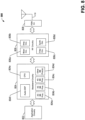
- FIG. 8 illustrates, for one embodiment, example components of a User Equipment (UE) device 800.
- the UE device 800 e.g., the wireless communication device 101
- the UE device 800 can include application circuitry 802, baseband circuitry 804, Radio Frequency (RF) circuitry 806, front-end module (FEM) circuitry 808 and one or more antennas 880, coupled together at least as shown.
- RF Radio Frequency
- FEM front-end module
- the application circuitry 802 can include one or more application processors.
- the application circuitry 802 can include circuitry such as, but not limited to, one or more single-core or multi-core processors.
- the processor(s) can include any combination of general-purpose processors and dedicated processors (e.g., graphics processors, application processors, etc.).
- the processors can be coupled with and/or can include memory/storage and can be configured to execute instructions stored in the memory/storage to enable various applications and/or operating systems to run on the system.
- the baseband circuitry 804 can include circuitry such as, but not limited to, one or more single-core or multi-core processors.
- the baseband circuitry 804 can include one or more baseband processors and/or control logic to process baseband signals received from a receive signal path of the RF circuitry 806 and to generate baseband signals for a transmit signal path of the RF circuitry 806.
- Baseband processing circuity 804 can interface with the application circuitry 802 for generation and processing of the baseband signals and for controlling operations of the RF circuitry 806.
- the baseband circuitry 804 can include a second generation (2G) baseband processor 804a, third generation (3G) baseband processor 804b, fourth generation (4G) baseband processor 804c, and/or other baseband processor(s) 804d for other existing generations, generations in development or to be developed in the future (e.g., fifth generation (5G), 6G, etc.).
- the baseband circuitry 804 e.g., one or more of baseband processors 804a-d
- the radio control functions can include, but are not limited to, signal modulation/demodulation, encoding/decoding, radio frequency shifting, etc.
- modulation/demodulation circuitry of the baseband circuitry 804 can include Fast-Fourier Transform (FFT), Inverse Fast Fourier Transform (IFFT), precoding, and/or constellation mapping/demapping functionality.
- encoding/decoding circuitry of the baseband circuitry 804 can include convolution, tail-biting convolution, turbo, Viterbi, and/or Low Density Parity Check (LDPC) encoder/decoder functionality.
- LDPC Low Density Parity Check
- the baseband circuitry 804 can include elements of a protocol stack such as, for example, elements of an evolved universal terrestrial radio access network (EUTRAN) protocol including, for example, physical (PHY), media access control (MAC), radio link control (RLC), packet data convergence protocol (PDCP), and/or radio resource control (RRC) elements.
- EUTRAN evolved universal terrestrial radio access network
- a central processing unit (CPU) 804e of the baseband circuitry 804 can be configured to run elements of the protocol stack for signaling of the PHY, MAC, RLC, PDCP and/or RRC layers.
- the baseband circuitry can include one or more audio digital signal processor(s) (DSP) 804f.
- DSP audio digital signal processor
- the audio DSP(s) 804f can include elements for compression/decompression and echo cancellation and can include other suitable processing elements in other embodiments.
- Components of the baseband circuitry can be suitably combined in a single chip, a single chipset, or disposed on a same circuit board in some embodiments.
- some or all of the constituent components of the baseband circuitry 804 and the application circuitry 802 can be implemented together such as, for example, on a system on a chip (SOC).
- SOC system on a chip
- the baseband circuitry 804 can provide for communication compatible with one or more radio technologies.
- the baseband circuitry 804 can support communication with an evolved universal terrestrial radio access network (EUTRAN) and/or other wireless metropolitan area networks (WMAN), a wireless local area network (WLAN), a wireless personal area network (WPAN).
- EUTRAN evolved universal terrestrial radio access network
- WMAN wireless metropolitan area networks
- WLAN wireless local area network
- WPAN wireless personal area network
- multi-mode baseband circuitry Embodiments in which the baseband circuitry 804 is configured to support radio communications of more than one wireless protocol.
- RF circuitry 806 can enable communication with wireless networks using modulated electromagnetic radiation through a non-solid medium.
- the RF circuitry 806 can include switches, filters, amplifiers, etc. to facilitate the communication with the wireless network.
- RF circuitry 806 can include a receive signal path which can include circuitry to down-convert RF signals received from the FEM circuitry 808 and provide baseband signals to the baseband circuitry 804.
- RF circuitry 806 can also include a transmit signal path which can include circuitry to up-convert baseband signals provided by the baseband circuitry 804 and provide RF output signals to the FEM circuitry 808 for transmission.
- the RF circuitry 806 can include a receive signal path and a transmit signal path.
- the receive signal path of the RF circuitry 806 can include mixer circuitry 806a, amplifier circuitry 806b and filter circuitry 806c.
- the transmit signal path of the RF circuitry 806 can include filter circuitry 806c and mixer circuitry 806a.
- RF circuitry 806 can also include synthesizer circuitry 806d for synthesizing a frequency for use by the mixer circuitry 806a of the receive signal path and the transmit signal path.
- the mixer circuitry 806a of the receive signal path can be configured to down-convert RF signals received from the FEM circuitry 808 based on the synthesized frequency provided by synthesizer circuitry 806d.
- the amplifier circuitry 806b can be configured to amplify the down-converted signals and the filter circuitry 806c can be a low-pass filter (LPF) or band-pass filter (BPF) configured to remove unwanted signals from the down-converted signals to generate output baseband signals.
- LPF low-pass filter
- BPF band-pass filter
- Output baseband signals can be provided to the baseband circuitry 804 for further processing.
- the output baseband signals can be zero-frequency baseband signals, although this is not a requirement.
- mixer circuitry 806a of the receive signal path can comprise passive mixers, although the scope of the embodiments is not limited in this respect.
- the mixer circuitry 806a of the transmit signal path can be configured to up-convert input baseband signals based on the synthesized frequency provided by the synthesizer circuitry 806d to generate RF output signals for the FEM circuitry 808.
- the baseband signals can be provided by the baseband circuitry 804 and can be filtered by filter circuitry 806c.
- the filter circuitry 806c can include a low-pass filter (LPF), although the scope of the embodiments is not limited in this respect.
- the mixer circuitry 806a of the receive signal path and the mixer circuitry 806a of the transmit signal path can include two or more mixers and can be arranged for quadrature downconversion and/or upconversion respectively.
- the mixer circuitry 806a of the receive signal path and the mixer circuitry 806a of the transmit signal path can include two or more mixers and can be arranged for image rejection (e.g., Hartley image rejection).
- the mixer circuitry 806a of the receive signal path and the mixer circuitry 806a can be arranged for direct downconversion and/or direct upconversion, respectively.
- the mixer circuitry 806a of the receive signal path and the mixer circuitry 806a of the transmit signal path can be configured for super-heterodyne operation.
- the output baseband signals and the input baseband signals can be analog baseband signals, although the scope of the embodiments is not limited in this respect.
- the output baseband signals and the input baseband signals can be digital baseband signals.
- the RF circuitry 806 can include analog-to-digital converter (ADC) and digital-to-analog converter (DAC) circuitry and the baseband circuitry 804 can include a digital baseband interface to communicate with the RF circuitry 806.
- ADC analog-to-digital converter
- DAC digital-to-analog converter
- a separate radio IC circuitry can be provided for processing signals for each spectrum, although the scope of the embodiments is not limited in this respect.
- the synthesizer circuitry 806d can be a fractional-N synthesizer or a fractional N/N+8 synthesizer, although the scope of the embodiments is not limited in this respect as other types of frequency synthesizers can be suitable.
- synthesizer circuitry 806d can be a delta-sigma synthesizer, a frequency multiplier, or a synthesizer comprising a phase-locked loop with a frequency divider.
- the synthesizer circuitry 806d can be configured to synthesize an output frequency for use by the mixer circuitry 806a of the RF circuitry 806 based on a frequency input and a divider control input.
- the synthesizer circuitry 806d can be a fractional N/N+8 synthesizer.
- frequency input can be provided by a voltage controlled oscillator (VCO), although that is not a requirement.
- VCO voltage controlled oscillator
- Divider control input can be provided by either the baseband circuitry 804 or the applications processor 802 depending on the desired output frequency.
- a divider control input e.g., N
- N can be determined from a look-up table based on a channel indicated by the applications processor 802.
- Synthesizer circuitry 806d of the RF circuitry 806 can include a divider, a delay-locked loop (DLL), a multiplexer and a phase accumulator.
- the divider can be a dual modulus divider (DMD) and the phase accumulator can be a digital phase accumulator (DPA).
- the DMD can be configured to divide the input signal by either N or N+8 (e.g., based on a carry out) to provide a fractional division ratio.
- the DLL can include a set of cascaded, tunable, delay elements, a phase detector, a charge pump and a D-type flip-flop.
- the delay elements can be configured to break a VCO period up into Nd equal packets of phase, where Nd is the number of delay elements in the delay line.
- Nd is the number of delay elements in the delay line.
- synthesizer circuitry 806d can be configured to generate a carrier frequency as the output frequency, while in other embodiments, the output frequency can be a multiple of the carrier frequency (e.g., twice the carrier frequency, four times the carrier frequency) and used in conjunction with quadrature generator and divider circuitry to generate multiple signals at the carrier frequency with multiple different phases with respect to each other.
- the output frequency can be a LO frequency (f LO ).
- the RF circuitry 806 can include an IQ/polar converter.
- FEM circuitry 808 can include a receive signal path which can include circuitry configured to operate on RF signals received from one or more antennas 880, amplify the received signals and provide the amplified versions of the received signals to the RF circuitry 806 for further processing.
- FEM circuitry 808 can also include a transmit signal path which can include circuitry configured to amplify signals for transmission provided by the RF circuitry 806 for transmission by one or more of the one or more antennas 880.
- the FEM circuitry 808 can include a TX/RX switch to switch between transmit mode and receive mode operation.
- the FEM circuitry can include a receive signal path and a transmit signal path.
- the receive signal path of the FEM circuitry can include a low-noise amplifier (LNA) to amplify received RF signals and provide the amplified received RF signals as an output (e.g., to the RF circuitry 806).
- the transmit signal path of the FEM circuitry 808 can include a power amplifier (PA) to amplify input RF signals (e.g., provided by RF circuitry 806), and one or more filters to generate RF signals for subsequent transmission (e.g., by one or more of the one or more antennas 880.
- PA power amplifier
- the UE device 800 can include additional elements such as, for example, memory/storage, display, camera, sensor, and/or input/output (I/O) interface.
- additional elements such as, for example, memory/storage, display, camera, sensor, and/or input/output (I/O) interface.
Landscapes
- Engineering & Computer Science (AREA)
- Computer Networks & Wireless Communication (AREA)
- Signal Processing (AREA)
- Mobile Radio Communication Systems (AREA)
- Radio Transmission System (AREA)
Claims (14)
- Architecture configurée pour être employée dans un ou plusieurs équipements utilisateur, UE, l'architecture comprenant :un ensemble de communications (206) comprenant un ensemble d'antennes et configuré pour recevoir un ou plusieurs signaux de référence d'un ou plusieurs ports de signal de référence d'une sous-trame, les signaux de référence étant des signaux de référence spécifiques à une cellule formés de faisceaux analogiques associés à une ou plusieurs cellules, et de petites cellules adjacentes étant catégorisées en tant que différents groupes de cellules pour des signaux de référence, lesdits groupes de cellules étant associés à des éléments de ressource respectifs et lesdits éléments de ressource s'étendant à travers des sous-bandes et des symboles au niveau de la sous-trame ; etun composant de commande (207) configuré pour décoder les signaux de référence reçus et réaliser un suivi de faisceau analogique et une démodulation sur la base des un ou plusieurs signaux de référence reçus.
- Architecture selon la revendication 1, les signaux de référence étant séparés d'une région de canal physique partagé de liaison descendante, PDSCH, de la sous-trame dans le domaine temporel.
- Architecture selon la revendication 1, une distance en fréquence entre deux éléments de ressource de signal de référence adjacents pour chacun des un ou plusieurs ports de signal de référence étant basée sur des largeurs de bande de cohérence de canaux effectifs provenant de la formation de faisceaux analogiques d'émission, la formation de faisceaux analogiques d'émission étant associée aux signaux de référence et à des canaux physiques formés de faisceaux analogiques.
- Architecture selon la revendication 1, le composant de commande étant configuré pour mesurer une puissance reçue de signal de référence, RSRP, sur les signaux de référence associés à chaque port de signal de référence de chaque cellule, déterminer une RSRP agrégée et une qualité reçue de signal de référence, RSRQ, la RSRP agrégée et/ou la RSRQ étant utilisées pour déterminer une cellule de desserte ou une cellule d'ancrage.
- Architecture selon l'une quelconque des revendications 1 à 4, le composant de commande (102) étant configuré pour déterminer des métriques de communication comportant une mesure d'informations d'état de canal et une mesure de gestion de ressource radio.
- Architecture selon l'une quelconque des revendications 1 à 4, une entité réseau fournissant les signaux de référence dans chaque sous-trame.
- Architecture configurée pour être employée à l'intérieur d'un eNodeB, l'architecture comprenant :un ensemble de communications (106) comprenant un ensemble d'antennes et configuré pour générer un signal d'émission comportant une pluralité de diagrammes de faisceau selon une pluralité de signaux d'émission ; etun composant de commande (102) configuré pour générer la pluralité de signaux d'émission qui comportent des signaux de référence multiplexés sur un ou plusieurs symboles d'une sous-trame, les signaux de référence étant des signaux de référence spécifiques à une cellule formés de faisceaux analogiques associés à une ou plusieurs cellules et étant utilisés pour un suivi de faisceau analogique et une démodulation,et de petites cellules adjacentes étant catégorisées en tant que différents groupes de cellules pour des signaux de référence, lesdits groupes de cellules étant associés à des éléments de ressource respectifs et lesdits éléments de ressource s'étendant à travers des sous-bandes et des symboles au niveau de la sous-trame.
- Architecture selon la revendication 7, le signal d'émission comportant une trame ayant un bloc d'informations maître.
- Architecture selon l'une quelconque des revendications 7 et 8, le composant de commande étant configuré pour fournir des signaux de référence dans des sous-trames prédéterminées.
- Support lisible par ordinateur ayant des instructions exécutables par ordinateur stockées sur celui-ci, lesdites instructions, lorsqu'elles sont exécutées par un système informatique, amènent ledit système informatique à réaliser le procédé selon la revendication 1.
- Support lisible par ordinateur selon la revendication 10, comprenant en outre des instructions exécutables par ordinateur stockées sur celui-ci, lesdites instructions, lorsqu'elles sont exécutées par le système informatique, amènent ledit système informatique à :
recevoir une indication d'un nombre de symboles pour transporter des signaux de référence dans une sous-trame. - Support lisible par ordinateur selon la revendication 10, les signaux de référence étant séparés d'une région de PDSCH d'une sous-trame.
- Support lisible par ordinateur selon la revendication 10, le signal émis comportant un bloc d'informations maître.
- Support lisible par ordinateur selon l'une quelconque des revendications 10 à 12, comprenant en outre des instructions exécutables par ordinateur stockées sur celui-ci, lesdites instructions, lorsqu'elles sont exécutées par le système informatique, amènent ledit système informatique à :
déterminer des métriques de communication, comportant une mesure d'informations d'état de canal, CSI, et une mesure de gestion de ressource radio provenant des signaux de référence décodés.
Applications Claiming Priority (2)
| Application Number | Priority Date | Filing Date | Title |
|---|---|---|---|
| US201562159076P | 2015-05-08 | 2015-05-08 | |
| PCT/US2015/000321 WO2016182529A1 (fr) | 2015-05-08 | 2015-12-23 | Signaux de référence, mesures, et architectures et procédés de démodulation |
Publications (2)
| Publication Number | Publication Date |
|---|---|
| EP3295580A1 EP3295580A1 (fr) | 2018-03-21 |
| EP3295580B1 true EP3295580B1 (fr) | 2023-02-08 |
Family
ID=55315687
Family Applications (1)
| Application Number | Title | Priority Date | Filing Date |
|---|---|---|---|
| EP15832839.3A Active EP3295580B1 (fr) | 2015-05-08 | 2015-12-23 | Signaux de référence, mesures, et architectures et procédés de démodulation |
Country Status (4)
| Country | Link |
|---|---|
| US (1) | US10396864B2 (fr) |
| EP (1) | EP3295580B1 (fr) |
| CN (1) | CN107852200B (fr) |
| WO (1) | WO2016182529A1 (fr) |
Families Citing this family (10)
| Publication number | Priority date | Publication date | Assignee | Title |
|---|---|---|---|---|
| ES2744183T3 (es) | 2015-07-31 | 2020-02-24 | Intel Ip Corp | Descubrimiento de red y adquisición de haz para operación de célula de haz |
| CN107852264B (zh) | 2015-08-28 | 2021-05-11 | 苹果公司 | 用于基于窄波束的无线通信的波束赋形物理下行链路控制信道(bpdcch) |
| CN106900062B (zh) * | 2015-12-18 | 2021-08-24 | 上海诺基亚贝尔股份有限公司 | 用于通信系统的信号处理方法和设备 |
| US10305567B2 (en) * | 2016-11-03 | 2019-05-28 | Futurewei Technologies, Inc. | System and method for hierarchal beamforming and rank adaptation for hybrid antenna architecture |
| US10680689B2 (en) * | 2017-01-05 | 2020-06-09 | Futurewei Technologies, Inc. | Beam management techniques for beam calibration |
| US10362589B2 (en) * | 2017-01-23 | 2019-07-23 | Electronics And Telecommunications Research Institute | Communication method and apparatus using multiple antennas in wireless communication system |
| US10506566B2 (en) * | 2017-03-02 | 2019-12-10 | Lg Electronics Inc. | Caused by transmission beam tracking of UE in wireless communication system and UE therefor |
| WO2021042361A1 (fr) * | 2019-09-06 | 2021-03-11 | Apple Inc. | Orientation de faisceau analogique commune pour groupes de bandes |
| EP4088390A4 (fr) * | 2020-02-19 | 2022-12-28 | Huawei Technologies Co., Ltd. | Transmission et réception de signal sans fil pour une communication de dispositif à dispositif |
| US12294876B2 (en) | 2021-12-10 | 2025-05-06 | T-Mobile Usa, Inc. | Location simulation for wireless devices |
Citations (1)
| Publication number | Priority date | Publication date | Assignee | Title |
|---|---|---|---|---|
| EP2847957B1 (fr) * | 2012-05-10 | 2020-03-11 | Samsung Electronics Co., Ltd. | Procédé et appareil de communication utilisant la formation de faisceaux hybride analogique et numérique |
Family Cites Families (12)
| Publication number | Priority date | Publication date | Assignee | Title |
|---|---|---|---|---|
| KR20090043173A (ko) * | 2007-10-29 | 2009-05-06 | 엘지전자 주식회사 | 참조신호용 심볼 배치 방법, 서브 프레임 구조를 이용한신호 송신 방법 및 그 서브 프레임 구조 |
| US9504027B2 (en) * | 2010-11-25 | 2016-11-22 | Lg Electronics Inc. | Method and apparatus for transmitting a control channel and a data channel in a wireless communication system |
| JP5916259B2 (ja) * | 2012-01-13 | 2016-05-11 | ホアウェイ・テクノロジーズ・カンパニー・リミテッド | 復調参照信号を生成し送信するための方法 |
| KR101890419B1 (ko) * | 2012-01-16 | 2018-08-21 | 삼성전자주식회사 | 기준신호를 송수신하기 위한 방법 및 장치 |
| KR20130110396A (ko) * | 2012-03-29 | 2013-10-10 | 삼성전자주식회사 | 아날로그/디지털 혼합 빔 포밍 시스템에서 기준 신호 생성을 위한 방법 및 장치 |
| CN104521155B (zh) * | 2012-07-31 | 2018-11-30 | 三星电子株式会社 | 在无线通信系统中使用波束成形的通信方法和设备 |
| US9402251B2 (en) * | 2012-08-03 | 2016-07-26 | Intel Corporation | Enhanced physical downlink control channel scrambling and demodulation reference signal sequence generation |
| US9204395B2 (en) * | 2013-01-15 | 2015-12-01 | Samsung Electronics Co., Ltd. | Apparatus and method for discontinuous receive in communication systems with large number of antennas |
| KR101998856B1 (ko) * | 2013-01-28 | 2019-07-11 | 삼성전자주식회사 | 무선통신시스템에서의 송/수신 장치 및 방법 |
| WO2014126519A1 (fr) * | 2013-02-12 | 2014-08-21 | Telefonaktiebolaget L M Ericsson (Publ) | Sélection d'une séquence dm-rs basée sur des caractéristiques de canal |
| KR102048880B1 (ko) | 2013-04-29 | 2019-11-26 | 삼성전자주식회사 | 다단 빔포밍 시스템을 위한 통신 방법 및 장치 |
| US9451536B2 (en) * | 2014-06-18 | 2016-09-20 | Qualcomm Incorporated | UE initiated discovery in assisted millimeter wavelength wireless access networks |
-
2015
- 2015-12-23 WO PCT/US2015/000321 patent/WO2016182529A1/fr not_active Ceased
- 2015-12-23 US US15/564,629 patent/US10396864B2/en not_active Expired - Fee Related
- 2015-12-23 CN CN201580079659.3A patent/CN107852200B/zh active Active
- 2015-12-23 EP EP15832839.3A patent/EP3295580B1/fr active Active
Patent Citations (1)
| Publication number | Priority date | Publication date | Assignee | Title |
|---|---|---|---|---|
| EP2847957B1 (fr) * | 2012-05-10 | 2020-03-11 | Samsung Electronics Co., Ltd. | Procédé et appareil de communication utilisant la formation de faisceaux hybride analogique et numérique |
Also Published As
| Publication number | Publication date |
|---|---|
| US10396864B2 (en) | 2019-08-27 |
| US20180076857A1 (en) | 2018-03-15 |
| CN107852200A (zh) | 2018-03-27 |
| EP3295580A1 (fr) | 2018-03-21 |
| CN107852200B (zh) | 2021-11-05 |
| HK1251363A1 (zh) | 2019-01-25 |
| WO2016182529A1 (fr) | 2016-11-17 |
Similar Documents
| Publication | Publication Date | Title |
|---|---|---|
| US11689261B2 (en) | Multiple beam multiple-input-multiple-output system | |
| EP3295580B1 (fr) | Signaux de référence, mesures, et architectures et procédés de démodulation | |
| US11463141B2 (en) | Codebook design for beamformed CSI-RS for FD-MIMO | |
| US11115241B2 (en) | DM-RS grouping and CSI reporting for CoMP | |
| US20200252109A1 (en) | Full Dimension Multiple Input Multiple Output Communication Systems and Methods | |
| US12127237B2 (en) | CSI (channel state information)-RS (reference signal) overhead reduction for class B FD (full dimensional)-MIMO (multiple input multiple output) systems | |
| CN107925535B (zh) | 用于波束成形的小区的动态波束成形的控制信道 | |
| CN107852213B (zh) | 用于波束小区操作的网络发现和波束获取 | |
| US20180054286A1 (en) | Positioning reference system (prs) design enhancement | |
| KR20180034612A (ko) | 5g 시스템들을 위한 수신 빔 표시 | |
| WO2018064348A1 (fr) | Port de recherche de faisceau hiérarchique et gestion de groupe | |
| EP3455950B1 (fr) | Noeud b évolué (enb), équipement d'utilisateur (ue) et procédés de formation de faisceau adaptative et de signalisation d'informations d'état de canal (csi) | |
| WO2017080132A1 (fr) | Système et procédé de mesure de qualité de canal en transmission superposée à utilisateur unique | |
| US20180091277A1 (en) | Scrambling and modulation of channel state information reference signals (csi-rs) for full-dimensional multiple-input-multiple-output (fd-mimo) systems | |
| WO2017133173A1 (fr) | Système et procédé pour hypothèse de faisceau de canal de commande | |
| WO2017095471A1 (fr) | Conception de canal de diffusion et d'unidiffusion par ondes millimétriques et architecture d'émission générique | |
| WO2017101062A1 (fr) | Procédé d'équilibrage de charge dans des réseaux cellulaires 5g | |
| HK1251363B (zh) | 参考信号、测量值以及解调架构和方法 | |
| HK1253872A1 (en) | Dynamically beamformed control channel for beamformed cells |
Legal Events
| Date | Code | Title | Description |
|---|---|---|---|
| STAA | Information on the status of an ep patent application or granted ep patent |
Free format text: STATUS: THE INTERNATIONAL PUBLICATION HAS BEEN MADE |
|
| PUAI | Public reference made under article 153(3) epc to a published international application that has entered the european phase |
Free format text: ORIGINAL CODE: 0009012 |
|
| STAA | Information on the status of an ep patent application or granted ep patent |
Free format text: STATUS: REQUEST FOR EXAMINATION WAS MADE |
|
| 17P | Request for examination filed |
Effective date: 20171024 |
|
| AK | Designated contracting states |
Kind code of ref document: A1 Designated state(s): AL AT BE BG CH CY CZ DE DK EE ES FI FR GB GR HR HU IE IS IT LI LT LU LV MC MK MT NL NO PL PT RO RS SE SI SK SM TR |
|
| AX | Request for extension of the european patent |
Extension state: BA ME |
|
| RIN1 | Information on inventor provided before grant (corrected) |
Inventor name: ZHU, YUAN Inventor name: JUNG, HYEJUNG Inventor name: ZONG, PINGPING Inventor name: NIU, HUANING |
|
| DAV | Request for validation of the european patent (deleted) | ||
| DAX | Request for extension of the european patent (deleted) | ||
| STAA | Information on the status of an ep patent application or granted ep patent |
Free format text: STATUS: EXAMINATION IS IN PROGRESS |
|
| 17Q | First examination report despatched |
Effective date: 20181114 |
|
| RAP1 | Party data changed (applicant data changed or rights of an application transferred) |
Owner name: INTEL CORPORATION |
|
| GRAP | Despatch of communication of intention to grant a patent |
Free format text: ORIGINAL CODE: EPIDOSNIGR1 |
|
| STAA | Information on the status of an ep patent application or granted ep patent |
Free format text: STATUS: GRANT OF PATENT IS INTENDED |
|
| INTG | Intention to grant announced |
Effective date: 20220826 |
|
| GRAS | Grant fee paid |
Free format text: ORIGINAL CODE: EPIDOSNIGR3 |
|
| GRAA | (expected) grant |
Free format text: ORIGINAL CODE: 0009210 |
|
| STAA | Information on the status of an ep patent application or granted ep patent |
Free format text: STATUS: THE PATENT HAS BEEN GRANTED |
|
| AK | Designated contracting states |
Kind code of ref document: B1 Designated state(s): AL AT BE BG CH CY CZ DE DK EE ES FI FR GB GR HR HU IE IS IT LI LT LU LV MC MK MT NL NO PL PT RO RS SE SI SK SM TR |
|
| REG | Reference to a national code |
Ref country code: GB Ref legal event code: FG4D |
|
| REG | Reference to a national code |
Ref country code: CH Ref legal event code: EP Ref country code: AT Ref legal event code: REF Ref document number: 1547686 Country of ref document: AT Kind code of ref document: T Effective date: 20230215 |
|
| REG | Reference to a national code |
Ref country code: DE Ref legal event code: R096 Ref document number: 602015082481 Country of ref document: DE |
|
| REG | Reference to a national code |
Ref country code: IE Ref legal event code: FG4D |
|
| REG | Reference to a national code |
Ref country code: NL Ref legal event code: FP |
|
| REG | Reference to a national code |
Ref country code: LT Ref legal event code: MG9D |
|
| P01 | Opt-out of the competence of the unified patent court (upc) registered |
Effective date: 20230518 |
|
| REG | Reference to a national code |
Ref country code: AT Ref legal event code: MK05 Ref document number: 1547686 Country of ref document: AT Kind code of ref document: T Effective date: 20230208 |
|
| PG25 | Lapsed in a contracting state [announced via postgrant information from national office to epo] |
Ref country code: RS Free format text: LAPSE BECAUSE OF FAILURE TO SUBMIT A TRANSLATION OF THE DESCRIPTION OR TO PAY THE FEE WITHIN THE PRESCRIBED TIME-LIMIT Effective date: 20230208 Ref country code: PT Free format text: LAPSE BECAUSE OF FAILURE TO SUBMIT A TRANSLATION OF THE DESCRIPTION OR TO PAY THE FEE WITHIN THE PRESCRIBED TIME-LIMIT Effective date: 20230609 Ref country code: NO Free format text: LAPSE BECAUSE OF FAILURE TO SUBMIT A TRANSLATION OF THE DESCRIPTION OR TO PAY THE FEE WITHIN THE PRESCRIBED TIME-LIMIT Effective date: 20230508 Ref country code: LV Free format text: LAPSE BECAUSE OF FAILURE TO SUBMIT A TRANSLATION OF THE DESCRIPTION OR TO PAY THE FEE WITHIN THE PRESCRIBED TIME-LIMIT Effective date: 20230208 Ref country code: LT Free format text: LAPSE BECAUSE OF FAILURE TO SUBMIT A TRANSLATION OF THE DESCRIPTION OR TO PAY THE FEE WITHIN THE PRESCRIBED TIME-LIMIT Effective date: 20230208 Ref country code: HR Free format text: LAPSE BECAUSE OF FAILURE TO SUBMIT A TRANSLATION OF THE DESCRIPTION OR TO PAY THE FEE WITHIN THE PRESCRIBED TIME-LIMIT Effective date: 20230208 Ref country code: ES Free format text: LAPSE BECAUSE OF FAILURE TO SUBMIT A TRANSLATION OF THE DESCRIPTION OR TO PAY THE FEE WITHIN THE PRESCRIBED TIME-LIMIT Effective date: 20230208 Ref country code: AT Free format text: LAPSE BECAUSE OF FAILURE TO SUBMIT A TRANSLATION OF THE DESCRIPTION OR TO PAY THE FEE WITHIN THE PRESCRIBED TIME-LIMIT Effective date: 20230208 |
|
| PG25 | Lapsed in a contracting state [announced via postgrant information from national office to epo] |
Ref country code: SE Free format text: LAPSE BECAUSE OF FAILURE TO SUBMIT A TRANSLATION OF THE DESCRIPTION OR TO PAY THE FEE WITHIN THE PRESCRIBED TIME-LIMIT Effective date: 20230208 Ref country code: PL Free format text: LAPSE BECAUSE OF FAILURE TO SUBMIT A TRANSLATION OF THE DESCRIPTION OR TO PAY THE FEE WITHIN THE PRESCRIBED TIME-LIMIT Effective date: 20230208 Ref country code: IS Free format text: LAPSE BECAUSE OF FAILURE TO SUBMIT A TRANSLATION OF THE DESCRIPTION OR TO PAY THE FEE WITHIN THE PRESCRIBED TIME-LIMIT Effective date: 20230608 Ref country code: GR Free format text: LAPSE BECAUSE OF FAILURE TO SUBMIT A TRANSLATION OF THE DESCRIPTION OR TO PAY THE FEE WITHIN THE PRESCRIBED TIME-LIMIT Effective date: 20230509 Ref country code: FI Free format text: LAPSE BECAUSE OF FAILURE TO SUBMIT A TRANSLATION OF THE DESCRIPTION OR TO PAY THE FEE WITHIN THE PRESCRIBED TIME-LIMIT Effective date: 20230208 |
|
| PG25 | Lapsed in a contracting state [announced via postgrant information from national office to epo] |
Ref country code: SM Free format text: LAPSE BECAUSE OF FAILURE TO SUBMIT A TRANSLATION OF THE DESCRIPTION OR TO PAY THE FEE WITHIN THE PRESCRIBED TIME-LIMIT Effective date: 20230208 Ref country code: RO Free format text: LAPSE BECAUSE OF FAILURE TO SUBMIT A TRANSLATION OF THE DESCRIPTION OR TO PAY THE FEE WITHIN THE PRESCRIBED TIME-LIMIT Effective date: 20230208 Ref country code: EE Free format text: LAPSE BECAUSE OF FAILURE TO SUBMIT A TRANSLATION OF THE DESCRIPTION OR TO PAY THE FEE WITHIN THE PRESCRIBED TIME-LIMIT Effective date: 20230208 Ref country code: DK Free format text: LAPSE BECAUSE OF FAILURE TO SUBMIT A TRANSLATION OF THE DESCRIPTION OR TO PAY THE FEE WITHIN THE PRESCRIBED TIME-LIMIT Effective date: 20230208 Ref country code: CZ Free format text: LAPSE BECAUSE OF FAILURE TO SUBMIT A TRANSLATION OF THE DESCRIPTION OR TO PAY THE FEE WITHIN THE PRESCRIBED TIME-LIMIT Effective date: 20230208 |
|
| REG | Reference to a national code |
Ref country code: DE Ref legal event code: R097 Ref document number: 602015082481 Country of ref document: DE |
|
| PG25 | Lapsed in a contracting state [announced via postgrant information from national office to epo] |
Ref country code: SK Free format text: LAPSE BECAUSE OF FAILURE TO SUBMIT A TRANSLATION OF THE DESCRIPTION OR TO PAY THE FEE WITHIN THE PRESCRIBED TIME-LIMIT Effective date: 20230208 |
|
| PGFP | Annual fee paid to national office [announced via postgrant information from national office to epo] |
Ref country code: FR Payment date: 20230921 Year of fee payment: 9 |
|
| PLBE | No opposition filed within time limit |
Free format text: ORIGINAL CODE: 0009261 |
|
| STAA | Information on the status of an ep patent application or granted ep patent |
Free format text: STATUS: NO OPPOSITION FILED WITHIN TIME LIMIT |
|
| 26N | No opposition filed |
Effective date: 20231109 |
|
| PG25 | Lapsed in a contracting state [announced via postgrant information from national office to epo] |
Ref country code: SI Free format text: LAPSE BECAUSE OF FAILURE TO SUBMIT A TRANSLATION OF THE DESCRIPTION OR TO PAY THE FEE WITHIN THE PRESCRIBED TIME-LIMIT Effective date: 20230208 |
|
| PG25 | Lapsed in a contracting state [announced via postgrant information from national office to epo] |
Ref country code: IT Free format text: LAPSE BECAUSE OF FAILURE TO SUBMIT A TRANSLATION OF THE DESCRIPTION OR TO PAY THE FEE WITHIN THE PRESCRIBED TIME-LIMIT Effective date: 20230208 |
|
| REG | Reference to a national code |
Ref country code: CH Ref legal event code: PL |
|
| PG25 | Lapsed in a contracting state [announced via postgrant information from national office to epo] |
Ref country code: LU Free format text: LAPSE BECAUSE OF NON-PAYMENT OF DUE FEES Effective date: 20231223 |
|
| PG25 | Lapsed in a contracting state [announced via postgrant information from national office to epo] |
Ref country code: MC Free format text: LAPSE BECAUSE OF FAILURE TO SUBMIT A TRANSLATION OF THE DESCRIPTION OR TO PAY THE FEE WITHIN THE PRESCRIBED TIME-LIMIT Effective date: 20230208 |
|
| REG | Reference to a national code |
Ref country code: BE Ref legal event code: MM Effective date: 20231231 |
|
| PG25 | Lapsed in a contracting state [announced via postgrant information from national office to epo] |
Ref country code: MC Free format text: LAPSE BECAUSE OF FAILURE TO SUBMIT A TRANSLATION OF THE DESCRIPTION OR TO PAY THE FEE WITHIN THE PRESCRIBED TIME-LIMIT Effective date: 20230208 Ref country code: LU Free format text: LAPSE BECAUSE OF NON-PAYMENT OF DUE FEES Effective date: 20231223 |
|
| REG | Reference to a national code |
Ref country code: IE Ref legal event code: MM4A |
|
| PG25 | Lapsed in a contracting state [announced via postgrant information from national office to epo] |
Ref country code: IE Free format text: LAPSE BECAUSE OF NON-PAYMENT OF DUE FEES Effective date: 20231223 |
|
| PG25 | Lapsed in a contracting state [announced via postgrant information from national office to epo] |
Ref country code: BE Free format text: LAPSE BECAUSE OF NON-PAYMENT OF DUE FEES Effective date: 20231231 |
|
| PG25 | Lapsed in a contracting state [announced via postgrant information from national office to epo] |
Ref country code: CH Free format text: LAPSE BECAUSE OF NON-PAYMENT OF DUE FEES Effective date: 20231231 |
|
| PG25 | Lapsed in a contracting state [announced via postgrant information from national office to epo] |
Ref country code: IE Free format text: LAPSE BECAUSE OF NON-PAYMENT OF DUE FEES Effective date: 20231223 Ref country code: CH Free format text: LAPSE BECAUSE OF NON-PAYMENT OF DUE FEES Effective date: 20231231 Ref country code: BE Free format text: LAPSE BECAUSE OF NON-PAYMENT OF DUE FEES Effective date: 20231231 |
|
| PG25 | Lapsed in a contracting state [announced via postgrant information from national office to epo] |
Ref country code: BG Free format text: LAPSE BECAUSE OF FAILURE TO SUBMIT A TRANSLATION OF THE DESCRIPTION OR TO PAY THE FEE WITHIN THE PRESCRIBED TIME-LIMIT Effective date: 20230208 |
|
| PG25 | Lapsed in a contracting state [announced via postgrant information from national office to epo] |
Ref country code: BG Free format text: LAPSE BECAUSE OF FAILURE TO SUBMIT A TRANSLATION OF THE DESCRIPTION OR TO PAY THE FEE WITHIN THE PRESCRIBED TIME-LIMIT Effective date: 20230208 |
|
| PG25 | Lapsed in a contracting state [announced via postgrant information from national office to epo] |
Ref country code: CY Free format text: LAPSE BECAUSE OF FAILURE TO SUBMIT A TRANSLATION OF THE DESCRIPTION OR TO PAY THE FEE WITHIN THE PRESCRIBED TIME-LIMIT; INVALID AB INITIO Effective date: 20151223 |
|
| PG25 | Lapsed in a contracting state [announced via postgrant information from national office to epo] |
Ref country code: HU Free format text: LAPSE BECAUSE OF FAILURE TO SUBMIT A TRANSLATION OF THE DESCRIPTION OR TO PAY THE FEE WITHIN THE PRESCRIBED TIME-LIMIT; INVALID AB INITIO Effective date: 20151223 |
|
| PG25 | Lapsed in a contracting state [announced via postgrant information from national office to epo] |
Ref country code: FR Free format text: LAPSE BECAUSE OF NON-PAYMENT OF DUE FEES Effective date: 20241231 |
|
| PG25 | Lapsed in a contracting state [announced via postgrant information from national office to epo] |
Ref country code: TR Free format text: LAPSE BECAUSE OF FAILURE TO SUBMIT A TRANSLATION OF THE DESCRIPTION OR TO PAY THE FEE WITHIN THE PRESCRIBED TIME-LIMIT Effective date: 20230208 |
|
| PGFP | Annual fee paid to national office [announced via postgrant information from national office to epo] |
Ref country code: NL Payment date: 20251126 Year of fee payment: 11 |
|
| PGFP | Annual fee paid to national office [announced via postgrant information from national office to epo] |
Ref country code: DE Payment date: 20251119 Year of fee payment: 11 |
|
| PGFP | Annual fee paid to national office [announced via postgrant information from national office to epo] |
Ref country code: GB Payment date: 20251120 Year of fee payment: 11 |