EP3295645B1 - Procédé et système de transmission sans effet rétroactif de données entre réseaux - Google Patents
Procédé et système de transmission sans effet rétroactif de données entre réseaux Download PDFInfo
- Publication number
- EP3295645B1 EP3295645B1 EP16741871.4A EP16741871A EP3295645B1 EP 3295645 B1 EP3295645 B1 EP 3295645B1 EP 16741871 A EP16741871 A EP 16741871A EP 3295645 B1 EP3295645 B1 EP 3295645B1
- Authority
- EP
- European Patent Office
- Prior art keywords
- data
- network
- communication
- application
- components
- Prior art date
- Legal status (The legal status is an assumption and is not a legal conclusion. Google has not performed a legal analysis and makes no representation as to the accuracy of the status listed.)
- Active
Links
Images


Classifications
-
- H—ELECTRICITY
- H04—ELECTRIC COMMUNICATION TECHNIQUE
- H04L—TRANSMISSION OF DIGITAL INFORMATION, e.g. TELEGRAPHIC COMMUNICATION
- H04L63/00—Network architectures or network communication protocols for network security
- H04L63/10—Network architectures or network communication protocols for network security for controlling access to devices or network resources
- H04L63/105—Multiple levels of security
-
- H—ELECTRICITY
- H04—ELECTRIC COMMUNICATION TECHNIQUE
- H04L—TRANSMISSION OF DIGITAL INFORMATION, e.g. TELEGRAPHIC COMMUNICATION
- H04L63/00—Network architectures or network communication protocols for network security
- H04L63/02—Network architectures or network communication protocols for network security for separating internal from external traffic, e.g. firewalls
-
- H—ELECTRICITY
- H04—ELECTRIC COMMUNICATION TECHNIQUE
- H04L—TRANSMISSION OF DIGITAL INFORMATION, e.g. TELEGRAPHIC COMMUNICATION
- H04L63/00—Network architectures or network communication protocols for network security
- H04L63/20—Network architectures or network communication protocols for network security for managing network security; network security policies in general
Definitions
- the invention relates to a method and an arrangement for the reaction-free transmission of data between networks with different security requirements, for example between industrial control networks and less critical diagnostic networks.
- cross-domain security solutions for the transmission of data between networks with different security requirements, so-called cross-domain security solutions, have so far been used in special areas such as communication with authorities, in which high security requirements apply and in which there is a security classification of documents or information.
- a cross-domain solution enables automated, secure exchange of documents and messages, such as emails, between zones with different security requirements.
- a key component is a data diode, which ensures unidirectional data communication, i.e. transport of data in only one direction.
- firewalls that filter the data communication according to configurable filter rules have hitherto been used for the coupling of industrial control networks, which usually have high security requirements, with a diagnostic network, an office network, or a public Internet, which usually only meet low security requirements.
- the data communication is permitted or blocked depending on the addresses of the communication partners and the communication protocol used, for example.
- the security requirements relate in particular to the availability and integrity of data transmission. This is a different objective than protecting confidentiality, as is often required for office applications or official applications.
- a data diode consisting of a transmission component and a reception component, which are connected to an optical transmission line or shielded twisted copper lines, is known, thereby realizing a unidirectional data transmission.
- the transmission component represents a proxy that is included in the data communication.
- Such a transmission component cannot reliably guarantee reaction-free data transmission.
- such a transmission component is located in the communication path of the safety-critical network, so that end-to-end communication between network components is interrupted.
- WO2016/096599A1 discloses a method and a device for the reaction-free acquisition of data from at least one device, which is arranged in a first network with high security requirements, in a second network with low security requirements.
- the document U.S. 2010/162399 discloses relevant prior art.
- Data transmission between two networks is non-reactive if no signals or data are introduced into the sending network during or as a result of the data transmission or if data in the first network can be changed.
- the freedom from feedback should not only be guaranteed with regard to the introduction or changing of signals by an external communication participant, the solution itself should be free of feedback.
- Known data diodes that implement a limited return channel, for example for the confirmation of TCP packets (acknowledgment), are therefore not to be regarded as reaction-free.
- Data diode solutions that require a special transmission component that has to be introduced into the communication path are also not suitable. Such data diodes therefore do not guarantee freedom from reactions and do not meet the required quality, such as is required for the approval of industrial control networks.
- first data from a first application is transmitted in a first network with high security requirements in a communication exclusively between components within the first network via a plurality of transmission lines, with data in the first network being transmitted by at least one Monitoring device per transmission line are recorded without feedback and transmitted to a second network with lower security requirements.
- the first data of a first application in the first network are thus transmitted exclusively between components within the first network and thus constitute end-to-end communication.
- This end-to-end communication is not broken up in the present invention, since the Communication is only overheard, but is not broken up by a separate component that does not belong to the first network. This reliably ensures that there are no reactions, ie it is ensured that no new data whatsoever are interspersed in the first network as a result of the transmission in a second network.
- no data within the first network is changed or Added data to the first network, since the eavesdropping on data only includes copying and transferring the copied data or data packets to a second network.
- the data packets or data are not evaluated in the monitoring device.
- the acquisition of the first data by a listening unit represents a function that is absolutely transparent for the communication in the first network.
- At least one monitoring unit per communication connection ensures that in a redundantly designed first network, the first data can be reliably recorded by the remaining communication connections even if one of the communication connections fails. If data is transmitted over a number of communication links either simultaneously or alternately, then here too, at least one monitoring unit per communication link ensures that all data is recorded. Further information or plausibility checks can also be derived from the acquisition of the data on different communication links. Even in the case of bidirectional communication between the components of a first network via different communication links, the acquisition of the data in both directions is ensured.
- the method is also suitable for tapping real-time-critical communication, since the first data can be copied without significant delay.
- real-time relevant information e.g. for a real-time critical control or regulation of an automation system, can be tapped and evaluated without any reaction.
- a first application is, for example, a diagnostic function in which diagnostic messages within a control network or a segment of the control network are sent from a component of the control network to a component within the control network designed as a diagnostic server be transmitted.
- a second application can be the control function, for example, in which control messages are also transmitted between the components of the first network, for example for a train protection network.
- the monitoring device does not represent an additional transmission component that is introduced into the communication as a proxy, for example. Only data that is being transmitted anyway is passively monitored. There is thus also no additional component for explicitly sending data from the second network into the first network.
- second data from a second application is transmitted between components within the second network, with the data being recorded in the second network by at least one second listening device and being transmitted to the first network.
- a reconstructed communication of the second application is created from the recorded data and second data is only transmitted to components of the first network if the reconstruction is successful.
- Two monitoring devices are thus combined, which, however, each function independently.
- a first implements a reaction-free one-way communication from the first network to the second network, as described above.
- a second implements a controlled return channel.
- the first eavesdropping device is still non-reactive as described above.
- the second component can inject communication into the first network, but without there being a network connection from the second network to the first network. This reliably prevents communication in the first network from being influenced by communication in the second network.
- changed diagnosis schedules or changed diagnosis queries with a high level of security against data manipulation be introduced.
- An influencing of the safety-relevant network through the transmission of the second data is minimized, since only controlled communication is used in the first network, in which the listened-to user data of the second network is used to form data communication in the first network and to inject it into the first network . Since there is no direct network communication from the second network to the first network, but rather data communication is formed within the first network, the data transmission in the first network is reliably prevented from being affected.
- the formation and sending of the data packets of the listened-to user data of the second network is carried out by a component of the first network, so that the data transmission of the first network is prevented from being influenced by the second network due to the principle.
- all recorded data are stored unfiltered in a data storage unit.
- this enables data from a real-time-relevant first or second application to be recorded quickly.
- the first data is filtered by a filter unit in the second network and the second data is filtered by a filter unit in the first network.
- the first or second data of the first or second application is filtered by evaluating the recorded data with regard to an application-specific identifier.
- the corresponding diagnostic data is identified and separable by a corresponding diagnostic network identifier, e.g. a VLAN tag.
- the data of interest—in this case diagnostic data—of a first application can thus be reliably filtered from the entire recorded data stream.
- a reconstructed communication of the first or second application from the first or second data is created in a reconstruction unit in the second or first network.
- response data packets that clearly belong to a request message are used to reconstruct the communication of the first or second application.
- the first data or the second data is stored in a data server and transmitted to components of the second or first network by an external command, at the request of components of the second or first network or initiated by the data server itself.
- this enables a delayed transmission or introduction of the first or second data into the second or first network.
- a time-controlled transmission of the data to the other network can be implemented. It can also be ensured in this way that only when the data has been completely transmitted to the respective other network is it imported into components of the network itself.
- all recorded data are stored unfiltered in a data storage unit.
- a transmission time of the recorded data is advantageously recorded and the transmission time is stored together with the recorded data, in particular with a digital signature.
- the arrangement according to the invention for the reaction-free transmission of data between networks with different security requirements, with first data being transmitted from a first application in a communication exclusively between components within the first network via a plurality of communication links in a first network with high security requirements comprises at least one monitoring device for each communication link , which is designed to detect data in the first network from a communication connection without any reaction and in a second network with lower security requirements to transmit and a data storage unit which is arranged in the second network and stores the collected data.
- Reaction-free network monitoring or a side channel is established by means of at least one monitoring unit per communication connection in order to record data transmitted within a first security-relevant network.
- the arrangement can therefore be used in particular for safety-relevant networks, such as control networks, in which safety-relevant control communications are transmitted via the same physical infrastructure, such as diagnostic data, for example.
- safety-relevant networks such as control networks
- diagnostic data such as diagnostic data
- the first data is reliably recorded and transmitted to the other network even if one communication connection fails. If the multiple communication links are used for different partial data sets, such as signaling messages and user data, for the first application, then all partial data sets can be reliably recorded.
- a monitoring device is arranged, for example, at two points, for example before and after a diagnosis server, or in the case of redundant transmission paths on each redundancy segment.
- the arrangement is therefore suitable for high-availability networks, such as security networks.
- the arrangement additionally comprises at least one second monitoring device, which is designed to record data in the second network and transmit it to the first network, and a second reconstruction unit, which is designed in such a way to create a reconstructed communication of the second application from the recorded data and only if the reconstruction is successful to transmit second data to components of the first network.
- Passive monitoring of the communication in the second network means that no dedicated transmission or reception component is required for data transmission between the networks. Influencing of the first network by the data transmission is thus minimized.
- the first or second monitoring unit is designed as a network decoupler, for example a network tap, or as a device with a network interface to the first network whose contacts are deactivated for transmission signals, or as a decoupling device for electromagnetic radiation.
- All of the above configurations of a monitoring unit passively acquire the data on the communication link on which they are arranged. This means that only data or signals are recorded without the possibility of introducing data into the communication link yourself. This also includes forwarding changed signals or data within the respective network. Such eavesdropping devices are available and accessible at low cost. A copy of the signals or data is thus achieved in a simple manner and thus a protocol break is prevented or protocol independence is achieved.
- the arrangement comprises a data storage unit which is designed in such a way that all recorded data are stored in an unfiltered manner.
- the arrangement also includes a filter unit which is designed to filter the first data or the second data from all of the recorded data. Furthermore, the arrangement additionally comprises a reconstruction unit, which is designed in such a way for the reconstruction of the communication of the first application only to use response data packets that clearly belong to a request message for evaluation.
- the amount of data recorded is thus reduced and, for example, reduced to the communication of a specific application.
- the arrangement also includes a data server which is designed to store the reconstructed first or second data.
- intercepted data can be successively collected and transmitted to the receiving network if it is fully available.
- the data server can be set up in such a way that the data is transmitted to the receiving network by an external command, at the request of components of the receiving network or initiated by the data server itself.
- the computer program product according to the invention which can be loaded directly into a memory of a digital computer, includes program code parts that are suitable for carrying out the steps of the method described.
- Networks with high security requirements are, for example, a control network in an automation system, via which manufacturing components are connected to one another and controlled, for example. Similar requirements are also present in control networks for train protection networks or power distribution systems, for example.
- security-critical networks are mostly closed or at least access-controlled control networks with bidirectional communication between individual components, such as field devices and control computers, diagnostic computers or monitoring computers. The communication is often real-time critical and/or security critical. There is end-to-end communication within the control network.
- the communication network is usually equipped with redundant communication links or transmission paths, such as a double bus system or a ring topology. Depending on the network load, several communication links can also be used. become frequent Data from different applications, such as for controlling or diagnosing the components, is transmitted via the same communication connections and only a virtual separation is implemented, for example by separate VLANs. Diagnostic data is transmitted, for example, from components such as field devices to a diagnostic server within the closed control network.
- the diagnostic data is usually not evaluated in this closed control network, but in an office network with lower security requirements.
- the first method step 1 represents the transmission of first data from a first application in the first network.
- the second method step 2 the first data are recorded and duplicated by at least one listening unit per communication link in the first network.
- method step 3 the duplicated data are transmitted from the monitoring device to a second network.
- the monitoring unit only picks up the first data from the communication connection, ie copies the data and forwards the copied data to the second network.
- the first data is not changed in the first network, but forwarded to the communication partner in the first network without delay.
- Eavesdropping is not detectable in the first network. No additional data is introduced into the first network by the monitoring unit, nor is it generated during the duplication. A change in the data forwarded within the first network is also ruled out. Listening in is therefore a transparent action in the first network and is passive in relation to the first data.
- the method is therefore particularly suitable for real-time relevant communication.
- the use of at least one eavesdropping device per communication connection ensures that all transmitted first data of the communication is recorded, even if a communication connection fails or if the transmission changes in time between the communication connections. If the first network is set up in a ring topology, each of the two communication links is monitored in the vicinity of the diagnosis server, for example.
- figure 2 shows a further embodiment of the method, in which, in addition to communication from the first to the second network, communication from the second network with lower security requirements to the first security-critical network is also represented.
- second data from a second application are transmitted between components within the second, less safety-critical network.
- This can be, for example, configuration data or software that is to be made available to the first network from the second network.
- data in the second network is recorded by at least one second monitoring device and, in method step 7, is transmitted to the first network.
- a reconstructed communication of the second application is now created from the recorded data and is only transmitted to the first network in method step 9 if the second data has been successfully reconstructed.
- the data transmitted to the second network are stored in a data storage unit.
- the first data can then be filtered from all of the recorded data by a filter unit in the second network.
- the second data can be filtered after transmission in the first network.
- a VLAN tag or another application identifier can be evaluated in the data packets.
- the communication of the first or second application can then be reconstructed from the filtered first or second data. This can ensure that recorded data is assigned to the correct application and, for example, faulty communication within the first or second application is registered. Measures such as a warning message or non-consideration of the corresponding data can then be derived from this. This can be further optimized if recorded data packets can be clearly assigned to a request message.
- the reception time of a response data packet to a request message can be limited to a specified time interval and only data packets within this specified time interval can be used for reconstruction.
- the data transmitted to the second or first network can also be stored unfiltered and used to monitor the first network.
- a transmission time of the recorded data is advantageously recorded.
- the recorded data and the time of transmission are advantageously stored with a digital signature. In this way, any manipulation of the data can be detected or an evaluation can be limited to the data with the correct digital signature. This allows conclusions to be drawn about possible manipulation of the data.
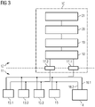
- FIG 3 now shows an arrangement 10 for the transmission of first data from a first network 11 with high security requirements in a second network 12 with lower security requirements.
- components 13.1, 13.2, 13.3, such as field devices and a control computer 15 and a diagnostic server 14 are connected to one another via a redundant first network.
- the redundant network is shown here, for example, as a double bus with communication links 16.1, 16.2.
- Each component 13.1, 13.2, 13.3, 14, 15 is connected to one of the two communication links 16.1, 16.2 with a respective network interface.
- real-time-critical, safety-critical measurement data and control data are transmitted via the communication links 16.1, 16.2.
- Any existing network components such as switches or hubs are not shown.
- the Internet protocol according to version 4 or version 6 is used as the network protocol.
- diagnostic data is also transmitted via the network infrastructure.
- These can be transmitted, for example, via a protocol of a standardized, unified architecture of an open platform communication, OPC UA protocol, a simple network management protocol, SNMP or, for example, a syslog protocol.
- the aim is now to transmit first data, here for example the diagnostic data, to the second network 12 without any reaction for the first network 11 and while maintaining the integrity of the data.
- An evaluation of the first data then takes place there.
- at least one monitoring device 17.1, 17.2 of the arrangement 10 is assigned to one of the redundant communication links 16.1, 16.2.
- the two listening devices 17.1, 17.2 independently of each other record the data transmitted on the first or second communication connection 16.1, 16.2, create a copy of the data, which is then transmitted to the second network 12 to a data storage unit 18 and stored there.
- the data storage unit 18 of the arrangement 10 can also record the time of the transmission of the first data to the second network 12 and store it as logging data, for example with a digital signature calculated using the data and time.
- the listening devices 17.1, 17.2 are purely passive network components.
- a monitoring unit can be used, for example, as a network decoupler that copies the data packets, or as a decoupling device that detects electromagnetic fields emitted by the communication line and converts them into signals or data.
- the data recorded from the first network can be stored in the data storage unit 18 unfiltered and reconstructed for monitoring purposes and, in particular, archived. Subsequent manipulation can be recognized by the digital signature, so that data transmissions can be checked and verified. This is particularly advantageous for safety-relevant networks that require approval.
- Filtering of the first data by the filter unit 19 of the arrangement 10 is possible, for example, by VLAN tags at the transmission level, an application-specific identifier at the transport level or at a protocol level above it. Redundantly present first data can be compared in a reconstruction unit 20 and only one of the data packets can be used in the reconstruction. In the reconstruction unit 20, the communication of the first application is reconstructed by, for example, only such first data being recorded which can be assigned to a request message or there is also a temporal correlation between the request message and the response data packet, for example corresponding to a predetermined time interval.
- the first data is then provided in the form of a database or an XML file, for example, and stored in a data server 21 of the arrangement 10 .
- the first data can be queried or evaluated as a whole or in parts.
- figure 4 now shows a reaction-free transmission of data from a second, less security-relevant network into a safety-critical first network 11.
- This is advantageous, for example, for downloading software, firmware, configuration or operating data, such as timetable data, which are to be made available within the safety-critical first network 11.
- it must be ensured that the control communication in the first network 11 cannot be influenced by the filling of a data server 121, here for example a loading server in the first network.
- the first network 11 includes components 113.1, 113.2, 113.3 and a first application server 114, for example a diagnostic server, and a second application server 115, for example a control server, and a data server 121. These network components are redundant, for example via a double data bus with communication links 116.1, 116.2 are each connected to one another via two network interfaces.
- the data server 121 is connected to a reconstruction unit 120 of the arrangement 100 .
- second data such as software versions, firmware or configuration or operating data, is transmitted from a provision client 123.1 to an external "dummy" loading server 123.2 via a communication connection 126.
- the arrangement 100 comprises a monitoring unit 117 which duplicates the second data during transmission on the communication link 126 in the second network 12 and transmits it to a data storage unit 118 of the arrangement 100 .
- the arrangement 100 also includes a filter unit 119 and a reconstruction unit 120 corresponding to the arrangement 10.
- the recorded data can be stored unfiltered and, for example, archived together with a transmission time for monitoring purposes.
- the filter unit 119 is designed in such a way that it filters out the second data from the data recorded by the monitoring unit 117.1, 117.2 and forwards it to a reconstruction unit 120.
- the Reconstruction Unit 120 is designed to transmit the second data of a reconstructed communication of the second application to the loading server 121 in the first network 11 only after a successful reconstruction.
- the arrangement 100 can be used, for example, for a controlled roll-out of SW patches.
- a validation unit is set up in the external loading server 123.2.
- the provision client 123.1 sends a start message to the loading server 123.2 via the communication link 126 and then starts transmitting the second data to the loading server 123.2.
- the second data is then checked by the validation unit in the loading server 123.2, for example using a virus scan, using a positive list or using a signature check.
- the external loading server 123.2 sends a confirmation message to the provision client 123.1.
- the start message, the second data and the final confirmation message are transmitted from the second network to the first network via the monitoring unit 117 and are evaluated and reconstructed there by the filter unit 119 or reconstruction unit 120 . Only when the confirmation message can be received and assigned to the start message in the reconstruction unit 120 are the reconstructed second data output to the data server 121 in the first network 11 .
- the transmission of the second data from the loading server 121 to the components 113.1, 113.2, 113.3, 114, 115 of the first network 11 can be started manually by a maintenance technician.
- a separate start command can also be transmitted via the loading mechanism according to the invention, which starts the transmission of the second data previously replicated on the data server 121 to the components 113.1, 113.2, 113.3, 114, 115 of the first network 11.
- the data server 121 in the first network prevents loaded data from being loaded directly or automatically onto the components of the first network.
- the second data to be loaded is checked in the second network by the external loading server 123.2, so that no additional load arises for this in the first network 11.
- a renewed transmission of second data in the second network 12 after a validation of the second data in the second network is no longer necessary. Manipulation of the second data in the second network 12 is therefore not possible.
- the individual units of the arrangement 10, 100 can also be designed in an integrated form as physically separate units.
- the inside figure 4 data server 121 shown as a physically separate unit can also be designed to be integrated with the arrangement 100.
Landscapes
- Engineering & Computer Science (AREA)
- Computer Security & Cryptography (AREA)
- Computer Hardware Design (AREA)
- Computing Systems (AREA)
- General Engineering & Computer Science (AREA)
- Computer Networks & Wireless Communication (AREA)
- Signal Processing (AREA)
- Data Exchanges In Wide-Area Networks (AREA)
- Computer And Data Communications (AREA)
- Communication Control (AREA)
Claims (16)
- Procédé destiné à la transmission sans effet rétroactif de données entre réseaux avec une exigence de sécurité différente, dans lequel dans un premier réseau avec une exigence de sécurité élevée des premières données sont transmises (2) par une première application dans une communication exclusivement entre des composants au sein du premier réseau par l'intermédiaire de plusieurs liaisons de communication (16.1, 16.2), dans lequel- des données dans le premier réseau (11) sont transmises par au moins un système de surveillance (17.1, 17.2) pour chaque liaison de communication (16.1, 16.2) qui réalise une communication unidirectionnelle, sont surveillées de manière passive et saisies sans effet rétroactif (3) et transmises (4) dans un second réseau (12) avec des exigences de sécurité moins élevées
et
dans lequel des secondes données d'une seconde application entre des composants (123.1, 123.2) sont transmises (5) au sein du second réseau (12),- des données dans le second réseau (12) sont saisies (6) par au moins un second dispositif de surveillance (117) et transmises (7) dans le premier réseau (11),- une communication reconstituée de la seconde application est générée (8) à partir des données saisies et, uniquement lors d'une reconstitution réussie, des secondes données sont transmises (9) à des composants du premier réseau. - Procédé selon la revendication 1, dans lequel toutes les données saisies dans l'unité de stockage de données (18, 118) sont stockées de manière non filtrée.
- Procédé selon l'une quelconque des revendications 1 à 2, dans lequel les premières données sont filtrées par le biais d'une unité formant filtre (19) dans le second réseau (12) resp. les secondes données sont filtrées par le biais d'une unité formant filtre (119) resp. d'un premier réseau (11) à partir de toutes les données saisies.
- Procédé selon la revendication 3, dans lequel les premières ou secondes données de la première resp. de la seconde application sont identifiées et filtrées par le biais d'une reconnaissance spécifique à l'application, en particulier sur le plan de transport.
- Procédé selon la revendication 3 ou 4, dans lequel dans le second réseau une communication reconstituée de la première application est générée à partir des premières données dans une unité de reconstitution (20) resp. dans le premier réseau une communication reconstituée de la seconde application est générée à partir des secondes données dans une unité de reconstitution (120).
- Procédé selon la revendication 5, dans lequel pour la reconstitution de la communication de la première resp. de la seconde application seuls des paquets de données en réponse appartenant sans équivoque à un message de demande sont utilisés.
- Procédé selon la revendication 5 ou 6, dans lequel seuls les paquets de données en réponse qui sont reçus dans un intervalle de temps prédéfini après un message de demande sont utilisés pour une reconstitution.
- Procédé selon l'une quelconque des revendications précédentes, dans lequel les premières données sont déposées dans un serveur de données (21) resp. les secondes données sont déposées dans un serveur de données (121) et par le biais d'une commande externe sont auto-initiées sur demande de composants du second resp. du premier réseau ou du serveur de données (21, 121) et transmises par le serveur de données (21) à des composants du second réseau (12) ou par le serveur de données (121) à des composants du premier réseau (11).
- Procédé selon l'une quelconque des revendications précédentes, dans lequel un moment de transmission des données saisies est saisi et le moment de transmission est mémorisé et signé numériquement conjointement avec les données acquises.
- Système destiné à la transmission sans effet rétroactif de données entre réseaux (11, 12) avec une exigence de sécurité différente, dans lequel dans un premier réseau (11) avec une exigence de sécurité plus élevée des premières données sont transmises par une première application dans une communication exclusivement entre des composants (13.1, 13.2, 13.3, 14, 15) au sein du premier réseau (11) par l'intermédiaire de plusieurs liaisons de communication (16.1, 16.2) et dans lequel des secondes données d'une seconde application entre composants (123.1, 123.2) du second réseau (12) sont transmises, comprenant- au moins un dispositif de surveillance (17.1, 17.2) pour chaque liaison de communication (16.1, 16.2) qui réalise une communication unidirectionnelle et est configuré de manière à surveiller de manière passive et à saisir sans effet rétroactif des données dans le premier réseau (11) par respectivement une liaison de communication (16.1, 16.2) et à les transmettre dans un second réseau (12) avec des exigences de sécurité plus faibles, et- une unité de stockage de données (18) qui est disposée dans le second réseau et stocke les données saisies,- au moins un second système de surveillance (117) qui est configuré de manière à saisir des données dans un second réseau (12) et à les transmettre dans le premier réseau (11), et- une seconde unité de reconstitution (120) qui est configurée de manière à générer une communication reconstituée de la seconde application à partir des données saisies et à transmettre uniquement en cas de reconstitution réussie des secondes données à des composants (113.1, 113.2, 113.3, 114, 115) du premier réseau (11).
- Système selon la revendication 10, dans lequel la première resp. la seconde unité de surveillance (17.1, 17.2) est configurée en tant que- découpleur de réseau (Tap),- dispositif avec une interface réseau avec le premier réseau, dont des contacts pour des signaux d'envoi sont désactivés, ou- dispositif de découplage pour un rayonnement électromagnétique.
- Système selon l'une quelconque des revendications 10 ou 11, dans lequel l'unité de stockage de données (18) est configurée de manière à stocker de manière non filtrée toutes les données saisies.
- Système selon l'une quelconque des revendications 10 ou 12, comprenant en outre une unité formant filtre (19, 119) qui est configurée de manière à filtrer les premières données resp. les secondes données à partir de toutes les données saisies.
- Système selon l'une quelconque des revendications 10 à 13, comprenant en outre une unité de reconstitution (20, 120) qui est configurée de manière à utiliser pour la reconstitution de la communication de la première application uniquement des paquets de données en réponse appartenant sans équivoque à un message de demande pour l'évaluation.
- Système selon l'une quelconque des revendications 10 à 14, comprenant en outre un serveur de données (21, 121) qui est configuré de manière à stocker les premières resp. secondes données reconstituées.
- Produit de programme informatique qui est chargeable directement dans une mémoire d'un ordinateur numérique, comprenant des parties de code de programme qui sont adéquates lors de leur exécution par le biais de l'ordinateur numérique pour mener à bien les étapes du procédé selon l'une quelconque des revendications 1 à 9.
Applications Claiming Priority (2)
| Application Number | Priority Date | Filing Date | Title |
|---|---|---|---|
| DE102015214993.5A DE102015214993A1 (de) | 2015-08-06 | 2015-08-06 | Verfahren und Anordnung zur rückwirkungsfreien Übertragung von Daten zwischen Netzwerken |
| PCT/EP2016/064783 WO2017021060A1 (fr) | 2015-08-06 | 2016-06-27 | Procédé et système de transmission sans effet rétroactif de données entre réseaux |
Publications (2)
| Publication Number | Publication Date |
|---|---|
| EP3295645A1 EP3295645A1 (fr) | 2018-03-21 |
| EP3295645B1 true EP3295645B1 (fr) | 2022-06-08 |
Family
ID=56511536
Family Applications (1)
| Application Number | Title | Priority Date | Filing Date |
|---|---|---|---|
| EP16741871.4A Active EP3295645B1 (fr) | 2015-08-06 | 2016-06-27 | Procédé et système de transmission sans effet rétroactif de données entre réseaux |
Country Status (8)
| Country | Link |
|---|---|
| US (1) | US11063957B2 (fr) |
| EP (1) | EP3295645B1 (fr) |
| CN (1) | CN107852415B (fr) |
| DE (1) | DE102015214993A1 (fr) |
| ES (1) | ES2918423T3 (fr) |
| HU (1) | HUE059244T2 (fr) |
| PL (1) | PL3295645T3 (fr) |
| WO (1) | WO2017021060A1 (fr) |
Families Citing this family (9)
| Publication number | Priority date | Publication date | Assignee | Title |
|---|---|---|---|---|
| DE102017203590A1 (de) * | 2017-03-06 | 2018-09-06 | Siemens Aktiengesellschaft | Verfahren und Anordnung zum rückwirkungsfreien Übermitteln von Informationen |
| EP3652905B1 (fr) * | 2017-07-10 | 2022-03-02 | BGC Partners, L.P. | Réseaux pour surveillance et répétition de paquets |
| DE102017217432A1 (de) | 2017-09-29 | 2019-04-04 | Siemens Mobility GmbH | Konzept zum unidirektionalen Übertragen von Daten |
| CN110336818A (zh) * | 2019-07-08 | 2019-10-15 | 郑州黑猫数字科技有限公司 | 一种基于数据感知的安全数据采集方法及系统 |
| EP3772206A1 (fr) * | 2019-07-31 | 2021-02-03 | Siemens Aktiengesellschaft | Adaptateur de réseau destiné au transfert unidirectionnel de données |
| DE102019211787A1 (de) * | 2019-08-06 | 2021-02-11 | Siemens Mobility GmbH | Verfahren und Kommunikationseinrichtung zur Datenübertragung zwischen Netzwerken, insbesondere mit unterschiedlicher Sicherheitsanforderungen |
| US11297071B2 (en) * | 2020-05-12 | 2022-04-05 | Siemens Mobility GmbH | Time-stamping for industrial unidirectional communication device with data integrity management |
| US12047460B2 (en) * | 2022-12-01 | 2024-07-23 | Saudi Arabian Oil Company | Cross-communication links for a unidirectional, bilateral data network |
| AT526785B1 (de) * | 2023-08-07 | 2024-07-15 | Creative Bits Og | Vorrichtung zum anlassbezogenen Unterbrechen einer zwei Netzwerkschnittstellen verbindenden Signalleitung |
Citations (3)
| Publication number | Priority date | Publication date | Assignee | Title |
|---|---|---|---|---|
| WO2016096599A1 (fr) * | 2014-12-18 | 2016-06-23 | Siemens Aktiengesellschaft | Procédé et dispositif de détection de données exempte de répercussions |
| WO2016156063A1 (fr) * | 2015-03-31 | 2016-10-06 | Siemens Aktiengesellschaft | Dispositif de couplage unidirectionnel, dispositif de requête et procédé pour la transmission sans rétroactivité de données |
| WO2017190997A1 (fr) * | 2016-05-02 | 2017-11-09 | Siemens Aktiengesellschaft | Procédé et système de contrôle d'intégrité permettant la surveillance de l'intégrité sans effet rétroactif |
Family Cites Families (13)
| Publication number | Priority date | Publication date | Assignee | Title |
|---|---|---|---|---|
| US6453345B2 (en) * | 1996-11-06 | 2002-09-17 | Datadirect Networks, Inc. | Network security and surveillance system |
| JP4119295B2 (ja) * | 2003-04-07 | 2008-07-16 | 東京エレクトロン株式会社 | 保守・診断データ蓄積サーバ、保守・診断データの蓄積・取得システム、保守・診断データの蓄積・提供システム |
| US20050129033A1 (en) | 2003-12-13 | 2005-06-16 | Gordy Stephen C. | Network tap for use with multiple attached devices |
| US8068415B2 (en) | 2007-04-18 | 2011-11-29 | Owl Computing Technologies, Inc. | Secure one-way data transfer using communication interface circuitry |
| US7649452B2 (en) * | 2007-06-29 | 2010-01-19 | Waterfall Solutions Ltd. | Protection of control networks using a one-way link |
| FR2924552B1 (fr) * | 2007-11-30 | 2009-11-20 | Thales Sa | Procede de securisation d'un canal bidirectionnel de communication et dispositif de mise en oeuvre du procede |
| US8589333B2 (en) * | 2008-08-19 | 2013-11-19 | Northrop Grumman Systems Corporation | System and method for information sharing across security boundaries |
| US20100162399A1 (en) * | 2008-12-18 | 2010-06-24 | At&T Intellectual Property I, L.P. | Methods, apparatus, and computer program products that monitor and protect home and small office networks from botnet and malware activity |
| US20120291089A1 (en) | 2011-05-13 | 2012-11-15 | Raytheon Company | Method and system for cross-domain data security |
| KR101334240B1 (ko) * | 2012-09-20 | 2013-11-28 | 한국전력공사 | 일방향 데이터 전송 시스템 |
| US9197654B2 (en) * | 2013-06-28 | 2015-11-24 | Mcafee, Inc. | Rootkit detection by using HW resources to detect inconsistencies in network traffic |
| JP2016537894A (ja) * | 2013-12-20 | 2016-12-01 | マカフィー, インコーポレイテッド | 局所/ホームネットワークのためのセキュリティゲートウェイ |
| CN104410623A (zh) | 2014-11-27 | 2015-03-11 | 柳州市网中网络策划中心 | 因特网管理系统 |
-
2015
- 2015-08-06 DE DE102015214993.5A patent/DE102015214993A1/de not_active Withdrawn
-
2016
- 2016-06-27 HU HUE16741871A patent/HUE059244T2/hu unknown
- 2016-06-27 US US15/742,930 patent/US11063957B2/en active Active
- 2016-06-27 PL PL16741871.4T patent/PL3295645T3/pl unknown
- 2016-06-27 EP EP16741871.4A patent/EP3295645B1/fr active Active
- 2016-06-27 WO PCT/EP2016/064783 patent/WO2017021060A1/fr not_active Ceased
- 2016-06-27 ES ES16741871T patent/ES2918423T3/es active Active
- 2016-06-27 CN CN201680046157.5A patent/CN107852415B/zh active Active
Patent Citations (3)
| Publication number | Priority date | Publication date | Assignee | Title |
|---|---|---|---|---|
| WO2016096599A1 (fr) * | 2014-12-18 | 2016-06-23 | Siemens Aktiengesellschaft | Procédé et dispositif de détection de données exempte de répercussions |
| WO2016156063A1 (fr) * | 2015-03-31 | 2016-10-06 | Siemens Aktiengesellschaft | Dispositif de couplage unidirectionnel, dispositif de requête et procédé pour la transmission sans rétroactivité de données |
| WO2017190997A1 (fr) * | 2016-05-02 | 2017-11-09 | Siemens Aktiengesellschaft | Procédé et système de contrôle d'intégrité permettant la surveillance de l'intégrité sans effet rétroactif |
Also Published As
| Publication number | Publication date |
|---|---|
| US20180375876A1 (en) | 2018-12-27 |
| ES2918423T3 (es) | 2022-07-15 |
| PL3295645T3 (pl) | 2022-09-26 |
| HUE059244T2 (hu) | 2022-11-28 |
| DE102015214993A1 (de) | 2017-02-09 |
| CN107852415A (zh) | 2018-03-27 |
| CN107852415B (zh) | 2021-08-20 |
| US11063957B2 (en) | 2021-07-13 |
| WO2017021060A1 (fr) | 2017-02-09 |
| EP3295645A1 (fr) | 2018-03-21 |
Similar Documents
| Publication | Publication Date | Title |
|---|---|---|
| EP3295645B1 (fr) | Procédé et système de transmission sans effet rétroactif de données entre réseaux | |
| DE112010001370B4 (de) | Signalübertragungsvorrichtung für einen Aufzug | |
| EP3207683B1 (fr) | Procédé et dispositif de détection de données exempte de répercussions | |
| EP2838220A1 (fr) | Procédé de transmission redondante de messages dans un réseau de communication industriel et appareil de communication | |
| DE102017217432A1 (de) | Konzept zum unidirektionalen Übertragen von Daten | |
| DE102011082969A1 (de) | Verfahren zum Betreiben eines Kommunikationsnetzwerkes und Netzwerkanordnung | |
| DE102014111361A1 (de) | Verfahren zum Betreiben einer Sicherheitssteuerung und Automatisierungsnetzwerk mit einer solchen Sicherheitssteuerung | |
| WO2020244983A1 (fr) | Dispositif de test de détection d'erreur pour une station d'abonné d'un système de bus série et procédé de test de mécanismes de détection d'erreur lors d'une communication dans un système de bus série | |
| EP0570338B1 (fr) | Procédé et dispositif pour la surveillance et la protection d'accès dans les réseaux de communication | |
| EP3414632B1 (fr) | Procédé et dispositif pour contrôler un traitement et une transmission de données dans une chaîne de sécurité d'un système de sécurité | |
| EP1410577A1 (fr) | Elements reseau destine a un reseau optique ayant tune fonction de securite, en particulier a un reseau optique a topologie annulaire | |
| DE102011086726B4 (de) | Verfahren zur redundanten Kommunikation zwischen einem Nutzer-Terminal und einem Leitsystem-Server | |
| EP3470939B1 (fr) | Procédé et système de surveillance de l'intégrité de sécurité d'une fonction de sécurité fournie par un système de sécurité | |
| EP3028409B1 (fr) | Filtrage d'un paquet de données par un dispositif de filtrage de réseau | |
| EP3665603B1 (fr) | Procédé et dispositif de transmission directe et sans retour des messages de journal | |
| EP3570499A1 (fr) | Procédé d'identification de connexion fonctionnellement sûre | |
| DE102012209445A1 (de) | Verfahren und Kommunikationssystem zur sicheren Datenübertragung | |
| DE102017123911A1 (de) | Verfahren und Vorrichtung zum Überwachen der Reaktionszeit einer durch ein Sicherheitssystem bereitgestellten Sicherheitsfunktion | |
| EP1121785B1 (fr) | Reseau et appareil de couplage pour la connexion de deux segments dans un tel reseau | |
| EP3957033B1 (fr) | Calculateur et procédé pour faire fonctionner un calculateur | |
| DE102021127310B4 (de) | System und Verfahren zur Datenübertragung | |
| DE102022211587B4 (de) | Sicherer Betrieb von redundanten, einfehlertoleranten Steuergeräten im Fahrzeug mit signierten Signalen | |
| DE102018221417B4 (de) | Fahrzeug mit einem Netzwerkverteiler zum Melden einer Störung in einem Kommunikationsnetzwerk | |
| DE102019204452A1 (de) | Verfahren und Vorrichtung zum Betreiben eines Steuergerätes in einem Verbund von Steuergeräten | |
| DE102016225181A1 (de) | Verfahren und Vorrichtung zum Austausch informationssicherheitsrelevanter Nachrichten |
Legal Events
| Date | Code | Title | Description |
|---|---|---|---|
| STAA | Information on the status of an ep patent application or granted ep patent |
Free format text: STATUS: THE INTERNATIONAL PUBLICATION HAS BEEN MADE |
|
| PUAI | Public reference made under article 153(3) epc to a published international application that has entered the european phase |
Free format text: ORIGINAL CODE: 0009012 |
|
| STAA | Information on the status of an ep patent application or granted ep patent |
Free format text: STATUS: REQUEST FOR EXAMINATION WAS MADE |
|
| 17P | Request for examination filed |
Effective date: 20171208 |
|
| AK | Designated contracting states |
Kind code of ref document: A1 Designated state(s): AL AT BE BG CH CY CZ DE DK EE ES FI FR GB GR HR HU IE IS IT LI LT LU LV MC MK MT NL NO PL PT RO RS SE SI SK SM TR |
|
| AX | Request for extension of the european patent |
Extension state: BA ME |
|
| RAP1 | Party data changed (applicant data changed or rights of an application transferred) |
Owner name: SIEMENS MOBILITY GMBH |
|
| DAV | Request for validation of the european patent (deleted) | ||
| DAX | Request for extension of the european patent (deleted) | ||
| STAA | Information on the status of an ep patent application or granted ep patent |
Free format text: STATUS: EXAMINATION IS IN PROGRESS |
|
| 17Q | First examination report despatched |
Effective date: 20200219 |
|
| GRAP | Despatch of communication of intention to grant a patent |
Free format text: ORIGINAL CODE: EPIDOSNIGR1 |
|
| STAA | Information on the status of an ep patent application or granted ep patent |
Free format text: STATUS: GRANT OF PATENT IS INTENDED |
|
| INTG | Intention to grant announced |
Effective date: 20210720 |
|
| GRAJ | Information related to disapproval of communication of intention to grant by the applicant or resumption of examination proceedings by the epo deleted |
Free format text: ORIGINAL CODE: EPIDOSDIGR1 |
|
| STAA | Information on the status of an ep patent application or granted ep patent |
Free format text: STATUS: EXAMINATION IS IN PROGRESS |
|
| INTC | Intention to grant announced (deleted) | ||
| REG | Reference to a national code |
Ref country code: DE Ref legal event code: R079 Ref document number: 502016014951 Country of ref document: DE Free format text: PREVIOUS MAIN CLASS: H04L0029060000 Ipc: H04L0009400000 |
|
| GRAP | Despatch of communication of intention to grant a patent |
Free format text: ORIGINAL CODE: EPIDOSNIGR1 |
|
| STAA | Information on the status of an ep patent application or granted ep patent |
Free format text: STATUS: GRANT OF PATENT IS INTENDED |
|
| INTG | Intention to grant announced |
Effective date: 20220126 |
|
| RIC1 | Information provided on ipc code assigned before grant |
Ipc: H04L 9/40 20220101AFI20220124BHEP |
|
| GRAS | Grant fee paid |
Free format text: ORIGINAL CODE: EPIDOSNIGR3 |
|
| GRAA | (expected) grant |
Free format text: ORIGINAL CODE: 0009210 |
|
| STAA | Information on the status of an ep patent application or granted ep patent |
Free format text: STATUS: THE PATENT HAS BEEN GRANTED |
|
| AK | Designated contracting states |
Kind code of ref document: B1 Designated state(s): AL AT BE BG CH CY CZ DE DK EE ES FI FR GB GR HR HU IE IS IT LI LT LU LV MC MK MT NL NO PL PT RO RS SE SI SK SM TR |
|
| REG | Reference to a national code |
Ref country code: GB Ref legal event code: FG4D Free format text: NOT ENGLISH |
|
| REG | Reference to a national code |
Ref country code: AT Ref legal event code: REF Ref document number: 1497683 Country of ref document: AT Kind code of ref document: T Effective date: 20220615 Ref country code: CH Ref legal event code: EP |
|
| REG | Reference to a national code |
Ref country code: DE Ref legal event code: R096 Ref document number: 502016014951 Country of ref document: DE |
|
| REG | Reference to a national code |
Ref country code: IE Ref legal event code: FG4D Free format text: LANGUAGE OF EP DOCUMENT: GERMAN |
|
| REG | Reference to a national code |
Ref country code: ES Ref legal event code: FG2A Ref document number: 2918423 Country of ref document: ES Kind code of ref document: T3 Effective date: 20220715 |
|
| REG | Reference to a national code |
Ref country code: NL Ref legal event code: FP |
|
| REG | Reference to a national code |
Ref country code: LT Ref legal event code: MG9D |
|
| PG25 | Lapsed in a contracting state [announced via postgrant information from national office to epo] |
Ref country code: SE Free format text: LAPSE BECAUSE OF FAILURE TO SUBMIT A TRANSLATION OF THE DESCRIPTION OR TO PAY THE FEE WITHIN THE PRESCRIBED TIME-LIMIT Effective date: 20220608 Ref country code: NO Free format text: LAPSE BECAUSE OF FAILURE TO SUBMIT A TRANSLATION OF THE DESCRIPTION OR TO PAY THE FEE WITHIN THE PRESCRIBED TIME-LIMIT Effective date: 20220908 Ref country code: LT Free format text: LAPSE BECAUSE OF FAILURE TO SUBMIT A TRANSLATION OF THE DESCRIPTION OR TO PAY THE FEE WITHIN THE PRESCRIBED TIME-LIMIT Effective date: 20220608 Ref country code: HR Free format text: LAPSE BECAUSE OF FAILURE TO SUBMIT A TRANSLATION OF THE DESCRIPTION OR TO PAY THE FEE WITHIN THE PRESCRIBED TIME-LIMIT Effective date: 20220608 Ref country code: GR Free format text: LAPSE BECAUSE OF FAILURE TO SUBMIT A TRANSLATION OF THE DESCRIPTION OR TO PAY THE FEE WITHIN THE PRESCRIBED TIME-LIMIT Effective date: 20220909 Ref country code: FI Free format text: LAPSE BECAUSE OF FAILURE TO SUBMIT A TRANSLATION OF THE DESCRIPTION OR TO PAY THE FEE WITHIN THE PRESCRIBED TIME-LIMIT Effective date: 20220608 Ref country code: BG Free format text: LAPSE BECAUSE OF FAILURE TO SUBMIT A TRANSLATION OF THE DESCRIPTION OR TO PAY THE FEE WITHIN THE PRESCRIBED TIME-LIMIT Effective date: 20220908 |
|
| REG | Reference to a national code |
Ref country code: HU Ref legal event code: AG4A Ref document number: E059244 Country of ref document: HU |
|
| PG25 | Lapsed in a contracting state [announced via postgrant information from national office to epo] |
Ref country code: RS Free format text: LAPSE BECAUSE OF FAILURE TO SUBMIT A TRANSLATION OF THE DESCRIPTION OR TO PAY THE FEE WITHIN THE PRESCRIBED TIME-LIMIT Effective date: 20220608 Ref country code: LV Free format text: LAPSE BECAUSE OF FAILURE TO SUBMIT A TRANSLATION OF THE DESCRIPTION OR TO PAY THE FEE WITHIN THE PRESCRIBED TIME-LIMIT Effective date: 20220608 |
|
| PG25 | Lapsed in a contracting state [announced via postgrant information from national office to epo] |
Ref country code: SM Free format text: LAPSE BECAUSE OF FAILURE TO SUBMIT A TRANSLATION OF THE DESCRIPTION OR TO PAY THE FEE WITHIN THE PRESCRIBED TIME-LIMIT Effective date: 20220608 Ref country code: SK Free format text: LAPSE BECAUSE OF FAILURE TO SUBMIT A TRANSLATION OF THE DESCRIPTION OR TO PAY THE FEE WITHIN THE PRESCRIBED TIME-LIMIT Effective date: 20220608 Ref country code: RO Free format text: LAPSE BECAUSE OF FAILURE TO SUBMIT A TRANSLATION OF THE DESCRIPTION OR TO PAY THE FEE WITHIN THE PRESCRIBED TIME-LIMIT Effective date: 20220608 Ref country code: PT Free format text: LAPSE BECAUSE OF FAILURE TO SUBMIT A TRANSLATION OF THE DESCRIPTION OR TO PAY THE FEE WITHIN THE PRESCRIBED TIME-LIMIT Effective date: 20221010 Ref country code: EE Free format text: LAPSE BECAUSE OF FAILURE TO SUBMIT A TRANSLATION OF THE DESCRIPTION OR TO PAY THE FEE WITHIN THE PRESCRIBED TIME-LIMIT Effective date: 20220608 Ref country code: CZ Free format text: LAPSE BECAUSE OF FAILURE TO SUBMIT A TRANSLATION OF THE DESCRIPTION OR TO PAY THE FEE WITHIN THE PRESCRIBED TIME-LIMIT Effective date: 20220608 |
|
| PG25 | Lapsed in a contracting state [announced via postgrant information from national office to epo] |
Ref country code: IS Free format text: LAPSE BECAUSE OF FAILURE TO SUBMIT A TRANSLATION OF THE DESCRIPTION OR TO PAY THE FEE WITHIN THE PRESCRIBED TIME-LIMIT Effective date: 20221008 |
|
| REG | Reference to a national code |
Ref country code: DE Ref legal event code: R097 Ref document number: 502016014951 Country of ref document: DE |
|
| PG25 | Lapsed in a contracting state [announced via postgrant information from national office to epo] |
Ref country code: MC Free format text: LAPSE BECAUSE OF FAILURE TO SUBMIT A TRANSLATION OF THE DESCRIPTION OR TO PAY THE FEE WITHIN THE PRESCRIBED TIME-LIMIT Effective date: 20220608 Ref country code: AL Free format text: LAPSE BECAUSE OF FAILURE TO SUBMIT A TRANSLATION OF THE DESCRIPTION OR TO PAY THE FEE WITHIN THE PRESCRIBED TIME-LIMIT Effective date: 20220608 |
|
| PLBE | No opposition filed within time limit |
Free format text: ORIGINAL CODE: 0009261 |
|
| STAA | Information on the status of an ep patent application or granted ep patent |
Free format text: STATUS: NO OPPOSITION FILED WITHIN TIME LIMIT |
|
| PG25 | Lapsed in a contracting state [announced via postgrant information from national office to epo] |
Ref country code: LU Free format text: LAPSE BECAUSE OF NON-PAYMENT OF DUE FEES Effective date: 20220627 Ref country code: IE Free format text: LAPSE BECAUSE OF NON-PAYMENT OF DUE FEES Effective date: 20220627 Ref country code: DK Free format text: LAPSE BECAUSE OF FAILURE TO SUBMIT A TRANSLATION OF THE DESCRIPTION OR TO PAY THE FEE WITHIN THE PRESCRIBED TIME-LIMIT Effective date: 20220608 |
|
| 26N | No opposition filed |
Effective date: 20230310 |
|
| PG25 | Lapsed in a contracting state [announced via postgrant information from national office to epo] |
Ref country code: SI Free format text: LAPSE BECAUSE OF FAILURE TO SUBMIT A TRANSLATION OF THE DESCRIPTION OR TO PAY THE FEE WITHIN THE PRESCRIBED TIME-LIMIT Effective date: 20220608 |
|
| PG25 | Lapsed in a contracting state [announced via postgrant information from national office to epo] |
Ref country code: FR Free format text: LAPSE BECAUSE OF NON-PAYMENT OF DUE FEES Effective date: 20220808 |
|
| PG25 | Lapsed in a contracting state [announced via postgrant information from national office to epo] |
Ref country code: MK Free format text: LAPSE BECAUSE OF FAILURE TO SUBMIT A TRANSLATION OF THE DESCRIPTION OR TO PAY THE FEE WITHIN THE PRESCRIBED TIME-LIMIT Effective date: 20220608 Ref country code: CY Free format text: LAPSE BECAUSE OF FAILURE TO SUBMIT A TRANSLATION OF THE DESCRIPTION OR TO PAY THE FEE WITHIN THE PRESCRIBED TIME-LIMIT Effective date: 20220608 |
|
| PG25 | Lapsed in a contracting state [announced via postgrant information from national office to epo] |
Ref country code: TR Free format text: LAPSE BECAUSE OF FAILURE TO SUBMIT A TRANSLATION OF THE DESCRIPTION OR TO PAY THE FEE WITHIN THE PRESCRIBED TIME-LIMIT Effective date: 20220608 |
|
| PG25 | Lapsed in a contracting state [announced via postgrant information from national office to epo] |
Ref country code: MT Free format text: LAPSE BECAUSE OF FAILURE TO SUBMIT A TRANSLATION OF THE DESCRIPTION OR TO PAY THE FEE WITHIN THE PRESCRIBED TIME-LIMIT Effective date: 20220608 |
|
| PG25 | Lapsed in a contracting state [announced via postgrant information from national office to epo] |
Ref country code: BG Free format text: LAPSE BECAUSE OF FAILURE TO SUBMIT A TRANSLATION OF THE DESCRIPTION OR TO PAY THE FEE WITHIN THE PRESCRIBED TIME-LIMIT Effective date: 20220608 |
|
| PG25 | Lapsed in a contracting state [announced via postgrant information from national office to epo] |
Ref country code: BG Free format text: LAPSE BECAUSE OF FAILURE TO SUBMIT A TRANSLATION OF THE DESCRIPTION OR TO PAY THE FEE WITHIN THE PRESCRIBED TIME-LIMIT Effective date: 20220608 |
|
| PGFP | Annual fee paid to national office [announced via postgrant information from national office to epo] |
Ref country code: PL Payment date: 20250623 Year of fee payment: 10 |
|
| PGFP | Annual fee paid to national office [announced via postgrant information from national office to epo] |
Ref country code: NL Payment date: 20250610 Year of fee payment: 10 Ref country code: BE Payment date: 20250618 Year of fee payment: 10 |
|
| PGFP | Annual fee paid to national office [announced via postgrant information from national office to epo] |
Ref country code: AT Payment date: 20250509 Year of fee payment: 10 |
|
| REG | Reference to a national code |
Ref country code: DE Ref legal event code: R081 Ref document number: 502016014951 Country of ref document: DE Owner name: SIEMENS MOBILITY GMBH, DE Free format text: FORMER OWNER: SIEMENS MOBILITY GMBH, 81739 MUENCHEN, DE |
|
| PGFP | Annual fee paid to national office [announced via postgrant information from national office to epo] |
Ref country code: HU Payment date: 20250825 Year of fee payment: 10 |
|
| PGFP | Annual fee paid to national office [announced via postgrant information from national office to epo] |
Ref country code: ES Payment date: 20250923 Year of fee payment: 10 |
|
| PGFP | Annual fee paid to national office [announced via postgrant information from national office to epo] |
Ref country code: DE Payment date: 20250820 Year of fee payment: 10 |
|
| PGFP | Annual fee paid to national office [announced via postgrant information from national office to epo] |
Ref country code: IT Payment date: 20250625 Year of fee payment: 10 |
|
| PGFP | Annual fee paid to national office [announced via postgrant information from national office to epo] |
Ref country code: GB Payment date: 20250710 Year of fee payment: 10 |
|
| PGFP | Annual fee paid to national office [announced via postgrant information from national office to epo] |
Ref country code: CH Payment date: 20250903 Year of fee payment: 10 |