EP3295654B1 - Konfiguration von netzwerkelementen zur automatisierten richtlinienbasierten leitweglenkung - Google Patents
Konfiguration von netzwerkelementen zur automatisierten richtlinienbasierten leitweglenkung Download PDFInfo
- Publication number
- EP3295654B1 EP3295654B1 EP16724790.7A EP16724790A EP3295654B1 EP 3295654 B1 EP3295654 B1 EP 3295654B1 EP 16724790 A EP16724790 A EP 16724790A EP 3295654 B1 EP3295654 B1 EP 3295654B1
- Authority
- EP
- European Patent Office
- Prior art keywords
- network
- network element
- ports
- forwarding
- server
- Prior art date
- Legal status (The legal status is an assumption and is not a legal conclusion. Google has not performed a legal analysis and makes no representation as to the accuracy of the status listed.)
- Active
Links
Images




Classifications
-
- H—ELECTRICITY
- H04—ELECTRIC COMMUNICATION TECHNIQUE
- H04L—TRANSMISSION OF DIGITAL INFORMATION, e.g. TELEGRAPHIC COMMUNICATION
- H04L47/00—Traffic control in data switching networks
- H04L47/10—Flow control; Congestion control
- H04L47/12—Avoiding congestion; Recovering from congestion
- H04L47/125—Avoiding congestion; Recovering from congestion by balancing the load, e.g. traffic engineering
-
- H—ELECTRICITY
- H04—ELECTRIC COMMUNICATION TECHNIQUE
- H04L—TRANSMISSION OF DIGITAL INFORMATION, e.g. TELEGRAPHIC COMMUNICATION
- H04L67/00—Network arrangements or protocols for supporting network services or applications
- H04L67/01—Protocols
- H04L67/10—Protocols in which an application is distributed across nodes in the network
- H04L67/1001—Protocols in which an application is distributed across nodes in the network for accessing one among a plurality of replicated servers
Definitions
- This disclosure relates in general to the field of communications and, more particularly, to configuration of network elements for automated policy-based routing.
- Data centers are increasingly used by enterprises for effective collaboration, data storage, and resource management.
- a typical data center network contains myriad network elements including servers, load balancers, routers, switches, etc.
- the network connecting the network elements provides secure user access to data center services and an infrastructure for deployment, interconnection, and aggregation of shared resources. Improving operational efficiency and optimizing utilization of resources in data centers are some of the challenges facing data center managers.
- Data center managers seek a resilient infrastructure that consistently supports diverse applications and services.
- a properly planned data center network provides application and data integrity and, further, optimizes application availability and performance.
- US2011/261811 discloses load-balancing via modulus distribution and TCP flow redirection due to server overload.
- a forwarding policy from a first network node coupled to a network element is received.
- the forwarding policy specifies an address of a second network node coupled to the network element.
- a plurality of ports of the network element are identified, wherein the second network node is accessible from the network element through each of the plurality of ports.
- the forwarding policy is applied to the plurality of ports of the network element. Network traffic received at a port of the plurality of ports from the second network node is forwarded to the first network node.
- FIG. 1 illustrates a block diagram of a system 100 comprising a service appliance 104 and a network element 108 having multiple paths 112 to one or more destination servers 116 in accordance with certain embodiments.
- System 100 also includes a plurality of client devices 120 coupled to the network element 108 through network 124.
- the destination servers 116 may be part of a server farm 128 or other grouping of devices operable to respond to requests from clients 120.
- the destination servers 116 are coupled to the network element 108 through networks 132a and 132b.
- Network services are often inserted into a network such as system 100.
- the network services may include, by way of nonlimiting example, load balancing or application delivery services.
- the network services may be performed by one or more service appliances 104, which may be server blades or line cards integrated into network elements 108 (e.g., switches, routers, etc.) or may be external appliances.
- the provision of network services typically necessitates manual configuration of network elements 108 and other network nodes (e.g., servers).
- a client device 120 when providing load balancing or application delivery services, sends a request (e.g., one or more packets) that is intercepted by a service application running on one or more of the service appliances 104.
- the one or more packets of the request may have a source address of the client device and a destination address of the service appliance (e.g., a virtual Internet Protocol (IP) address that may be associated with one or more services that may be provided by each of servers 116 of server farm 128).
- IP Internet Protocol
- the service application of service appliance 104 is configured to select a server (e.g., destination server 116) among a group of servers (e.g., server farm 128) to fulfill the request.
- the service application may then change the destination address of the one or more packets to an address of the selected destination server and forward the packets having the source address of the client device and the destination address of the selected server to the selected server.
- routing/redirection policies may be set up on various network nodes (e.g., network elements 108) in between the service appliance 104 and the destination server 116.
- network nodes e.g., network elements 108
- the process of manually configuring policies on each network node to handle traffic redirection (so that return traffic from the destination server to the client is sent to the service appliance 104) and manually updating configuration policies based on the availability of the destination servers is tedious, time consuming, and error-prone.
- Various embodiments may include establishing a communication channel between a service appliance and a network element; receiving, at the network element from the service appliance, a forwarding policy that requests the network element to forward predetermined packets (e.g., packets received from one or more destination servers) to the service appliance; identify which ports of the network element are included in routes to the one or more destination servers, implementing the forwarding policy on the identified ports of the network element, and sending the forwarding policy to other network elements that are located between the network element and the one or more destination servers.
- the other network elements may perform a similar process to ensure that return traffic is directed back to the service appliance 104 before delivery to the client 120.
- a network element 108 may determine whether to forward the return packet towards the service appliance 104 based on the forwarding policy and will transmit the return packet towards the service appliance 104 in the event of an affirmative determination (if the network element 108 is adjacent the service appliance it will deliver the return packet to the service appliance). In at least some embodiments, network element 108 may set the "next hop" IP address of return traffic reaching the network element to the IP address of the service appliance 104 without modifying packets of the return traffic.
- the network element 108 then forwards the return traffic to the service appliance, which then directs the return traffic to the client with a source address of the service appliance 104 and a destination address of the client device 120 (e.g., the service appliance 104 may modify the source address of the packets to the IP address of the service appliance).
- Client devices 120 may be any suitable computing devices operable to send and receive network traffic (e.g., data packets).
- a "computing device" may be or comprise, by way of non-limiting example, a computer, workstation, server, mainframe, embedded computer, embedded controller, embedded sensor, personal digital assistant, laptop computer, cellular telephone, IP telephone, smart phone, tablet computer, convertible tablet computer, computing appliance, network appliance, receiver, wearable computer, handheld calculator, virtual machine, virtual appliance, or any other electronic, microelectronic, or microelectromechanical device for processing and communicating data.
- a client device may include an appropriate operating system, such as Microsoft Windows, Linux, Android, Mac OSX, Apple iOS, Unix, or similar operating system.
- Client devices 120 may be communicatively coupled to one another and to other network resources via network 124.
- Network element 108 may be any device or system operable to process and/or forward traffic in conjunction with forwarding policies.
- network elements may comprise network switches, routers, servers (physical servers or servers virtually implemented on physical hardware), machines (physical machine or machines virtually implemented on physical hardware), end user devices, access points, cable boxes, gateways, bridges, loadbalancers, firewalls, inline service nodes, proxies, processors, modules; other suitable devices, components, elements, proprietary appliances, or objects operable to exchange, receive, and transmit information in a network environment; or a combination of two or more of these.
- a network element may include any suitable hardware, software, components, modules, interfaces, or objects that facilitate operations associated with processing and/or forwarding network traffic.
- Network element 108 may be deployed in a data center, as an aggregation node (to aggregate traffic from a plurality of access domains), within a core network, or in other suitable configuration.
- network element 108 includes a multi-port network bridge that processes and routes data at a data link layer (Layer 2).
- network element 108 may process and/or route data at other various layers such as a Layer 3 network layer, Layer 4 (with network address translation and load distribution), Layer 7 (load distribution based on application specific transactions), or at multiple layers (e.g., Layer 2 and Layer 3).
- functionalities of a switch may be integrated into other network elements such as gateways, routers, or servers.
- network element 108 is a managed switch (e.g., managed using a command line interface (CLI), a web interface, etc.).
- network element is a Cisco® N7K switch.
- a network element 108 may connect to service appliance 104 over a communication channel 136 (e.g., over a port-channel).
- a "communication channel” encompasses a physical transmission medium (e.g., a wire), or a logical connection (e.g., a radio channel, a network connection) used to convey information signals (e.g., data packets, control packets, etc.) from one or more senders (e.g., network element 108) to one or more receivers (e.g., service appliance 104).
- a communication channel can include one or more communication links, which may be physical (e.g., wire) or logical (e.g., data link, wireless link, etc.).
- Termination points of communication channels can include interfaces such as Ethernet ports, serial ports, etc.
- communication channel 136 may be a single channel deployed for both control messages (i.e., messages that include control packets) and data messages (i.e., messages that include data packets).
- service appliance 104 may be a discrete (and generally separate) hardware device or virtual machine with integrated software (e.g., firmware), designed to provide one or more network services including load balancing, firewall, intrusion prevention, virtual private network (VPN), proxy, or other network services.
- firmware e.g., firmware
- service appliance 104 is assigned an IP address (which in some embodiments may be a virtual IP address) or other address to which clients may address network traffic. Clients may request a service from server farm 128 (or other group of servers) by sending a request to the address of the service appliance 104. The traffic is delivered to the service appliance 104 by the network element 108 based on the destination address (matching the address of the service appliance) of the traffic.
- the service appliance 104 is operable to load balance the traffic received from clients 120 among a plurality of servers 116, based on any suitable criteria, such as the source IP address, source media access control (MAC) address, source port, protocol (e.g., one or more L3 protocols such as IPv4 or IPv6 or one or more L4 protocols such as Transmission Control Protocol (TCP) or User Datagram Protocol (UDP)), one or more QoS parameters, one or more virtual local area network (VLAN) identifiers, and/or other suitable information associated with (e.g., specified by) the header or body of one or more packets of the network traffic.
- MAC source media access control
- protocol e.g., one or more L3 protocols such as IPv4 or IPv6 or one or more L4 protocols such as Transmission Control Protocol (TCP) or User Datagram Protocol (UDP)
- TCP Transmission Control Protocol
- UDP User Datagram Protocol
- QoS parameters e.g., Transmission Control Protocol (TCP) or User Datagram Protocol (
- the service appliance may then send the network traffic to the destination server. For example, the service appliance may modify the destination address of the packet to be the address (e.g., IP address) of the destination server 116 and then send the packet through the network element 108 towards the destination server.
- the service appliance may modify the destination address of the packet to be the address (e.g., IP address) of the destination server 116 and then send the packet through the network element 108 towards the destination server.
- network element 108 may be configured with an intelligent service card manager module (ISCM), and service appliance 104 may be configured with a corresponding intelligent service card client module (ISCC).
- ISCM and ISCC can form part of an infrastructure for configuring service appliance 104 on the network element 108, e.g., as a virtual line card in network element 108.
- the ISCM and ISCC may comprise any suitable logic, including hardware, software, or a combination thereof.
- the ISCM or ISCC may comprise software executed by a processor.
- the ISCC and ISCM may be configured to allow service appliance 104 to appear as a virtual line card, or some other virtual network node/entity.
- line card and “service module” are interchangeably used herein to refer to modular electronic circuits interfacing with telecommunication lines (such as copper wires or optical fibers) and that offer a pathway to the rest of a telecommunications network.
- Service appliance may be referred to simply as “appliance” or “module” herein.
- a virtual line card is interchangeable (in certain instances) with an ISCM.
- a virtual service module (or a virtual line card) is a logical instance (of a service module) providing the same functionalities (as the service module).
- Service modules may perform various functions including providing network services (e.g., similar to service appliances).
- One difference between a service module and a service appliance is that the service module is physically located within a network element, for example, on an appropriate physical slot.
- Virtual service modules are similarly configurable within a network element.
- a (external) service appliance 104 may connect to a network element 108 (e.g., switch) and behave like a service module within the network element without having to take up a physical slot in the network element.
- a network element 108 e.g., switch
- Such configurations may consolidate the provisioning of appliances and enable the appliances to have the benefits of being a service module within the network element.
- the task for provisioning and configuring of these service appliances is performed mostly by the infrastructure provided on the network element, making it easy for network administrators to add/remove service appliances in the network.
- an appliance user can enjoy the benefit of a service module's simple configuration and operation using the infrastructure of network element 108.
- setting up service appliance 104 for network configurations may be unnecessary.
- Substantially all such configurations may be made via network element 108, instead of service appliance 104.
- Service appliance 104 may offload (i.e., transfer) any network (e.g., L2/L3 network) specific control plane and data plane operations to network element 108.
- Data path acceleration that leverages an application specific integrated circuit (ASIC) (potentially embedded in network element 108) may also be possible in various embodiments.
- Network element 108 may communicate control messages to service appliance 104 over communication channel 136.
- configuration and provisioning of services within service appliance 104 may be implemented via network element 108.
- a service appliance 104 or a network element 108 may include one or more portions of one or more computer systems. In particular embodiments, one or more of these computer systems may perform one or more steps of one or more methods described or illustrated herein. In particular embodiments, one or more computer systems may provide functionality described or illustrated herein. In some embodiments, encoded software running on one or more computer systems may perform one or more steps of one or more methods described or illustrated herein and/or provide functionality described or illustrated herein.
- the components of the one or more computer systems may comprise any suitable physical form, configuration, number, type, and/or layout. Where appropriate, one or more computer systems may be unitary or distributed, span multiple locations, span multiple machines, or reside in a cloud, which may include one or more cloud components in one or more networks.
- Service appliance 104 may load balance among servers 116 belonging to one or more server farms 128 coupled to network element 108.
- a server farm 128 comprises one or more servers 116 operable to communicate with clients 120.
- various servers 116 within server farm 128 may each be operable to provide one or more services to clients 120.
- servers 116 may be redundant with each other such that any server of at least a subset of servers of the server farm may provide the same service(s) to clients 120.
- client 120 may send a server 116 a request, server 116 may perform processing based on the request, and may respond to the client with the requested data.
- individual servers in server farm 128 may communicate with other servers in the same server farm 128 via one or more network elements (e.g., switches).
- Servers in server farm 128 may communicate with servers in another server farm via one or more network elements 108 in various implementations.
- a server may refer to any device configured to communicate network traffic with clients 120 via one or more networks.
- server may encompass computers, virtual machines, network appliances, application servers, routers, switches, gateways, bridges, load balancers, firewalls, processors, modules, or any other suitable device, component, proprietary element, or object operable to exchange information in a network environment.
- the servers 116 may include any suitable hardware, software, components, modules, interfaces, or objects that facilitate the operations thereof. This may be inclusive of appropriate algorithms and communication protocols that allow for the effective exchange of data or information.
- server farm 128 may be replaced with a LAN connecting desktop computers in a small office.
- server farm 128 may be replaced with a network of wireless communication devices.
- server farm 128 may be replaced with one or more supercomputers.
- Various other configurations and devices are contemplated within the broad framework of the present disclosure.
- the networks described herein may be any suitable network or combination of one or more networks operating on one or more suitable networking protocols.
- a network may represent a series of points, nodes, or network elements and interconnected communication paths for receiving and transmitting packets of information that propagate through a communication system.
- a network may include one or more firewalls, routers, switches, security appliances, antivirus servers, or other useful network devices.
- a network offers a communicative interface between sources and/or hosts, and may comprise any local area network (LAN), wireless local area network (WLAN), metropolitan area network (MAN), Intranet, Extranet, Internet, wide area network (WAN), virtual private network (VPN), cellular network, or any other appropriate architecture or system that facilitates communications in a network environment depending on the network topology.
- a network can comprise any number of hardware or software elements coupled to (and in communication with) each other through a communications medium.
- a network may include one or more network elements 108 in the path from a source node coupled to the network and a destination node.
- a network may simply comprise a connection such as a cable (e.g., an Ethernet cable), air, or other transmission medium.
- Network element 108 may reach the destination server 116 via any number of different paths, such as network path 112a or network path 112b.
- a network path is comprised of the network segments and network nodes that data from a source passes through on its way to a destination.
- network path 112a may include a first port of network element 108 while network path 112b includes a second port of network element 108.
- network paths may or may not share one or more segments or network nodes.
- packets sent between network element 108 and destination server 116 may leave from the same port of network element 108, but may still travel different paths to the destination server 116.
- a packet from client 120a to destination server 116 may travel from a first port of network element 108 through path 112a to destination server 116 while a packet from destination server 116 to client 120a may travel through path 112b to a second port of network element 108 on its way to client 120a.
- each port of the switch has the same weight (i.e., traffic is equally likely to exit the switch at each port) and there may be no predetermined way to know which of the ports will be used to reach the server 116 or which of the ports will be used for return traffic from the server.
- ECMP equal cost multi-path
- a network element 108 may determine which of its ports may be used to reach the server 116.
- an ISCM registers with a unified/unicast routing information base (URIB) to determine the route and nexthop port through which network element 108 can reach the destination server 116.
- URIB unified/unicast routing information base
- a URIB is a software module running on a control plane of network element 108 and may communicate with the ISCM via one or more APIs.
- a URIB may have information about which IP routes are set up for each port of the network element.
- the ISCM may communicate the IP address of the destination server and the URIB will return one or more nexthop IP addresses and/or one or more ports through which the nexthop IP addresses may be reached. If the URIB only returns one nexthop port at a time, the appropriate APIs can be called multiple times to obtain all the nexthop ports in the ECMP case. Subsequently, the forwarding policy will be applied on each of the identified ports.
- the network element 108 may store an indication of which ports the forwarding policy has been applied to, such that if the server 116 later becomes unreachable through one or more of the ports, the forwarding policy may be removed from each port from which the server 116 is unreachable.
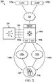
- FIG. 2 illustrates a block diagram of a system 200 comprising a service appliance 104 and a network element 108a having multiple virtual device contexts (VDCs) 140 each having at least one path to one or more destination servers 116 in accordance with certain embodiments.
- Network element 108a may have any of the characteristics described herein with respect to network element 108 and vice versa.
- VDCs 140a and 140b allow the network element 108 to be virtualized at the device level, presenting the physical network element as multiple logical devices. Each configured VDC 140 presents itself as a unique device to connected users within the framework of the physical network element.
- a VDC 140 may run as a separate logical entity within the network element, maintaining its own unique set of running software processes, having its own configuration, and being managed by a separate administrator in some situations.
- a VDC 140 may contain its own unique and independent set of VLANs and virtual route forwarding instances (VRFs).
- VRF virtual route forwarding instances
- Each VDC 140 may have physical ports allocated to it, thus allowing for the hardware data plane to be virtualized as well.
- the physical switch ports of network element 108 are resources that cannot be shared between VDC 140s.
- a separate management domain can manage the VDC 140 itself, thus allowing the management plane itself to also be virtualized.
- a network element capable of being configured with VDCs has a default setting where all physical ports on the network element are assigned to a default VDC 140 (e.g. VDC 140a).
- VDC 140a e.g. VDC 140a
- an administrator may be required to assign a set of physical ports from the default VDC 140a to the newly created VDC 140b, providing the new VDC 140b with a means to communicate with other devices on the network.
- a physical port is assigned to a particular VDC 140, it is bound exclusively to that VDC 140, and no other VDC 140 has access to that port.
- inter-VDC communication is not facilitated from within the network element 108, but a discrete external connection must be made between ports of different VDC 140s to allow communication between them.
- a client device 120 may communicate with the server 116 through any of multiple VDCs 140 of a network element 108.
- client device 120a might send a request to the server via network path 144a using VDC 140a, but receive a response from the server 116 through network path 144b using VDC 140b.
- traffic may be sent from the client to the server using a first VLAN associated with VDC 140a while return traffic may be sent from the server to the client using a second VLAN associated with VDC 140b.
- Each VDC 140 may be associated with its own instance of an ISCM. However, each ISCM instance is local to its particular VDC and does not manage the operation of other VDCs or their physical ports.
- a network element 108 may include or provide access to a global database that is accessible by each VDC (e.g., via its ISCM) of the network element 108.
- One ISCM may create a forwarding policy, store the policy in the shared database, and notify the other ISCMs of the network element that a policy has been added to the shared database.
- Each other ISCM on the network element 108 may then access the new policy from the shared database and determine whether the VDC is able to reach the server 116 and the service appliance 104.
- the forwarding policy is applied to all of the physical ports of the VDC that are able to reach the server 116.
- the global shared database is consulted to determine all the VDCs in which the policy is applied and delete requests are sent out accordingly.
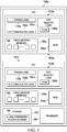
- FIG. 3 illustrates a block diagram of a network element 108a in accordance with certain embodiments.
- the network element 108a is configured to include two VDCs 140a and 140b, though a network element 108 may be configured with any suitable number of VDCs including zero (in which case the components illustrated inside of a VDC 140 may be associated with the entire network element 108 rather than a VDC 140 of the network element).
- the network element 108a also includes processor 148 and storage 152.
- network element 108a includes a computer system to facilitate performance of its operations.
- a computer system may include a processor, storage, and one or more communication interfaces, among other components.
- network element 108a comprises a computer system that includes one or more processors 148, storage 152, and one or more communication interfaces 156 that are virtualized through VDC 140a and 140b. These components may work together in order to provide functionality described herein.
- a communication interface 156 may be used for the communication of signaling and/or data between network element 108 and one or more networks (e.g., 124, 132a, or 132b) and/or network nodes (e.g., servers 116, service appliance 104) coupled to a network or other communication channel.
- communication interface 156 may be used to send and receive network traffic such as data packets.
- Each communication interface 156 may send and receive data and/or signals according to any suitable standard such as Asynchronous Transfer Mode (ATM), Frame Relay, or Gigabit Ethernet (or other IEEE 802.3 standard).
- communication interface 156 comprises one or more physical ports 160 that may each function as an ingress and/or egress port.
- communication interface 156 may comprise a plurality of Ethernet ports.
- Processor 148 may be a microprocessor, controller, or any other suitable computing device, resource, or combination of hardware, stored software and/or encoded logic operable to provide, either alone or in conjunction with other components of network element 108, network element functionality.
- network element 108 may utilize multiple processors to perform the functions described herein.
- the processor can execute any type of instructions to achieve the operations detailed herein in this Specification.
- the processor could transform an element or an article (e.g., data) from one state or thing to another state or thing.
- the activities outlined herein may be implemented with fixed logic or programmable logic (e.g., software/computer instructions executed by the processor) and the elements identified herein could be some type of a programmable processor, programmable digital logic (e.g., a field programmable gate array (FPGA), an erasable programmable read only memory (EPROM), an electrically erasable programmable ROM (EEPROM)) or an ASIC that includes digital logic, software, code, electronic instructions, or any suitable combination thereof.
- FPGA field programmable gate array
- EPROM erasable programmable read only memory
- EEPROM electrically erasable programmable ROM
- Storage 152 may comprise any form of volatile or non-volatile memory including, without limitation, magnetic media (e.g., one or more tape drives), optical media, random access memory (RAM), read-only memory (ROM), flash memory, removable media, or any other suitable local or remote memory component or components.
- Storage 152 may store any suitable data or information utilized by network element 108, including software embedded in a computer readable medium, and/or encoded logic incorporated in hardware or otherwise stored (e.g., firmware).
- Storage 152 may also store the results and/or intermediate results of the various calculations and determinations performed by processor 148.
- software to perform the functions of the ISCMs 164 when executed by a processor may be stored in storage 152.
- storage 152 also includes global forwarding policies database 168 which may be accessible by all of the ISCMs 164 of the various VDCs 140 as described earlier.
- each VDC 140 includes its own instance of an ISCM 164, a communication interface 156 with one or more physical ports 160, and forwarding logic 172.
- the ISCM may be capable of communicating the forwarding policies received from a service appliance 104, another ISCM 164, (e.g., of the same or a different network element 108), or a network administrator to other portions of network element 108 (e.g., to forwarding logic 172).
- ISCM 164 may also offer various functionalities such as handling (i.e., accommodating, managing, processing, etc.) messages between a network element 108 or a VDC 140 of a network element and one or more service appliances 104.
- handling i.e., accommodating, managing, processing, etc.
- functions in association with such messages may concern high availability activities, timer events, packet switch stream, American Standard Code for Information Interchange (ASCII) generation, logging, event handling, health monitoring, debugging, etc.
- ASCII American Standard Code for Information Interchange
- ISCM 164 and a corresponding ISCC of service appliance 104 may perform auto-discovery and bootstrap to establish an appropriate control channel.
- applications in service appliance 104 may send control messages (e.g., using the UDP socket interface) to the ISCC through an application control plane.
- the application control plane generally encompasses one or more software components for performing workflow management, self-management, and other application control layer processes.
- the ISCC may forward the control messages to an ISCM 164 of network element 108a over communication channel 136.
- ISCM 164 and the ISCC may communicate via UDP packets; however, various other protocols and formats may be accommodated by the teachings of the present disclosure.
- ISCM 164 may use processor 148 and storage 152 to perform functions associated with the service appliance 104 in network element 108.
- service appliance 104 may be provisioned with (or have access to) a processor and similar storage, which the ISCC may use to perform functions described herein in service appliance 104.
- Forwarding logic 172 may be operable to apply forwarding policies indicated by APBR requests (e.g., policies that may be automatically distributed to and implemented by the necessary network elements in a network without manual configuration at each network element) or user-specified traffic forwarding policies to traffic received via communication interface 156 and send the traffic processed by the policies to communication interface 156 for forwarding out of the appropriate port 160 of network element 108.
- forwarding logic 172 includes parsing logic 176, key construction logic 180, and port selection logic 184.
- forwarding logic 172 may comprise programmable logic (e.g., software/computer instructions executed by a processor), fixed logic, programmable digital logic (e.g., an FPGA, an EPROM, an EEPROM, or other device), an ASIC that includes digital logic, software, code, electronic instructions, or any suitable combination thereof.
- forwarding logic 172 comprises an ASIC or other device that is operable to perform customized traffic forwarding in hardware by utilizing logic (e.g., one or more memories such as TCAM 188) that is reprogrammable by an entity (e.g., ISCM 164) based on traffic customization information (e.g., APBR requests or traffic forwarding policies received from a network administrator).
- parsing logic 176 the functions of parsing logic 176, key construction logic 180, and port selection logic 184 are performed in hardware by such logic (in contrast to an implementation where such functions may be performed through software instructions executed by a network processor).
- Reconfiguration of the logic may be performed by storing different values in memory of the forwarding logic 172 such as TCAM 188 or other memory element while the rest of the forwarding logic 172 remains fixed.
- the values stored in the memory may provide control inputs to forwarding logic 172, but are not typical instructions that are part of an instruction set executed by a processor.
- the network element 108 may process incoming traffic (e.g., switch/bridge or route the traffic) at much higher speeds (e.g., at line rate) than a device that utilizes a network processor to process incoming network traffic.
- any of the operations of the various forwarding logic elements may be performed in software (e.g., with the use of a processor 148).
- Parsing logic 176 may be operable to receive packets from a port 160 of network element 108.
- the parsing logic 176 may be configured to parse information from a received packet.
- Parsing logic 176 may be configured to parse any suitable information, such as one or more protocols associated with (e.g., included within) the packet (such as an L3 or L4 protocol), a source address (e.g., IP address, MAC address, or other address) of the packet, a destination address (e.g., IP address, MAC address, or other address) of the packet, one or more ports (e.g., source or destination L4 port) associated with the packet, a VLAN identifier, a QoS value, or other suitable information from the header or body of a packet.
- protocols associated with e.g., included within
- a source address e.g., IP address, MAC address, or other address
- a destination address e.g., IP address, MAC address, or other
- the information to be parsed by parsing logic 176 is based on the information included within various forwarding policies implemented by network element 108 or a VDC thereof (which could include forwarding policies associated with various different ports of network element 108). In some embodiments, the parsing logic 176 is configured on a port-by-port basis, such that packets from each port may be parsed based on the forwarding policies associated with that port.
- the information parsed by parsing logic 176 is passed to key construction logic 180.
- Key construction logic constructs a key from the output of the parsing logic 176.
- the key may contain all or a portion of the information parsed from a packet.
- the key is then passed to the port selection logic 184.
- forwarding logic 172 may receive forwarding policies from ISCM 164 and configure itself to implement the forwarding policies. For example, forwarding logic 172 may store forwarding policies associated with a particular port 160 in a content addressable memory, such as a TCAM 188.
- a TCAM is a species of memory that is addressed by memory contents rather than address, and which provides very fast searching.
- a TCAM is a species of CAM in which the search can include "don't care" values that require only part of a search tag to be matched.
- the key generated by key construction logic 180 may be passed to the port selection logic 184.
- the port selection logic 184 uses the key to perform a lookup in the TCAM 188.
- Port selection logic 184 will then forward the traffic through the appropriate port 160 of network element 108 based on a forwarding policy that that matches the information in the key from the packet (and has the highest priority if multiple forwarding policies match the key).
- a forwarding policy may indicate that an incoming packet should be forwarded to the service appliance 104.
- the forwarding policy may indicate that the next hop IP address for the packet should be an IP address of the service appliance 104.
- a routing table associated with the network element 108 (or the appropriate VDC 140) may be modified accordingly, such that the packet may be routed from the network element 108 to the IP address of the service appliance 104 via a port 160 facing the service appliance 104.
- the routing table is stored in a separate memory (e.g., static random access memory) from the forwarding policies (e.g., TCAM 188).
- ISCM 164 receives forwarding policies (e.g., via APBR requests) and converts the forwarding policies into a format suitable for use by forwarding logic 208 before communicating these policies to forwarding logic 208.
- the forwarding policies may be used to generate one or more Access Control Lists (ACLs) and routemaps.
- ACLs Access Control Lists
- FIG. 4 illustrates a block diagram of a system 400 having multiple L3 network hops between a service appliance 104 and one or more destination servers 116 in accordance with certain embodiments.
- system 400 includes a network element 108b coupled to client 120 via network 124 and to service appliance 104 via communication channel 136.
- Network element 108b may be coupled to server farm 128 through another network element 108c.
- Network elements 108b and 108c may have any suitable characteristics described herein in connection with network elements 108 and 108a.
- Each network element 108 may be an L3 hop in the path from the service appliance 104 to the server farm 128.
- the forwarding policy to send return traffic from the servers 116 to the service appliance 104 should be implemented by each L3 hop (i.e., network element 108) to redirect the return traffic to the port through which the appliance can be reached.
- each L3 hop i.e., network element 108
- return traffic from server 116 to client device 120 might be routed from network element 108c to a network node in the network 124, thus bypassing network element 108b and service appliance 104.
- a network operation such as ping or traceroute may be used to determine the route a packet will take from the network element to the server 116.
- a network operation such as ping or traceroute may be used to determine the route a packet will take from the network element to the server 116.
- multiple UDP, Internet Control Message Protocol Echo Request, or TCP SYN packets may be addressed to the server 116.
- Time-to-live (TTL) values of the packets also known as hop limits
- network element 108b may determine a port through which the destination server 116 may be reached (i.e., the port through which the next hop may be reached). The forwarding policy will be applied on this port.
- the policy will be entered in the global forwarding policies database 168 and will also be sent to the network element that is the next hop (e.g., network element 108c) in the route to the destination server 116.
- the network element 108c at the next hop receives the forwarding policy, it will look up the port on which it can reach the destination server 116, apply the policy on that port (e.g., by setting the next hop for return traffic received at the port to the IP address of the network element 108 that it received the forwarding policy from), and store the policy in its own database 168. This process may be repeated for each network element 108 in the route to the destination server 116.
- FIG. 5 illustrates a block diagram of a system 500 having multiple L2 nodes and/or L3 network hops between a service appliance 104 and one or more destination servers 116 in accordance with certain embodiments.
- any particular network element 108 (or VDC thereof) between client 120 and a destination server may function as a router (e.g., as an L3 network hop) and/or as a switch (e.g., as an L2 node).
- a discovery protocol may be run by the ISCM instances of the network elements 108 to facilitate application of forwarding policies on the appropriate network elements 108 (or VDCs thereof) in order to direct return traffic from a destination server 116 back to the service appliance 104 that sent the traffic.
- the discovery protocol may result in one of the ISCM instances being selected to host a communication server. All other ISCM instances may communicate with the communication server (e.g., the host ISCM) using a client/server model. Thus, ISCM instances do not communicate network configuration information (e.g., forwarding policies) to each other directly, but would communicate the configuration information to the communication server, which would then communicate the configuration information to the other ISCM instances.
- any suitable L2 or L3 multicast protocol may be used by the ISCM instances 164 to discover each other ISCM instance 164 in the network.
- the discovery procedure may be performed at any suitable time such as on startup, when a new IMSC comes online, or when a host IMSC goes offline.
- Any suitable parameters of the ISCM instances may be shared with the other ISCM instances to facilitate selection of the host ISCM instance.
- each ISCM may multicast an identifier that is unique to the ISCM.
- each ISCM instance may multicast an ISCM identifier comprising a number unique to the network element 108 that is running the ISCM instance (e.g., a chassis serial number of the network element) concatenated with an identifier of a VDC associated with the ISCM instance (or a default value if no VDC instances are running on the network element 108 running the ISCM).
- an ISCM identifier comprising a number unique to the network element 108 that is running the ISCM instance (e.g., a chassis serial number of the network element) concatenated with an identifier of a VDC associated with the ISCM instance (or a default value if no VDC instances are running on the network element 108 running the ISCM).
- Each ISCM may be configured to determine whether it should host the communication server based on the parameters received from the other ISCM instances. Similarly, each ISCM may determine which ISCM is hosting the communication server based on the received parameters. In one example, the ISCM having the lowest valued ISCM identifier is selected as the host, though other suitable methods may be used to select the host ISCM (e.g., the highest valued ISCM identifier, etc.).
- the ISCM acting as the host may send out parameters that the other ISCMs (acting as clients) may use to communicate with the communication server hosted by the host ISCM.
- Any suitable communication protocol may be used to communicate between the client ISCMs and the communication server.
- the Extensible Messaging and Presence Protocol (XMPP) is used and the host ISCM will configure the communication server to be an XMPP server and send out parameters associated with the XMPP server to the other ISCMs.
- XMPP Extensible Messaging and Presence Protocol
- an L2 multicast mechanism or an L3 multicast or broadcast mechanism may be used instead of XMPP.
- the parameters associated with the communication server may be sent out by each ISCM during the discovery phase.
- each ISCM may send parameters that would be needed by the other ISCMs if that ISCM were to host the communication server.
- the parameters sent by one or more of the ISCMs may include (in addition to the aforementioned ISCM ID), an IP address associated with the ISCM (i.e., the IP address of the VDC or network element 108 running the ISCM), a port to be used to communicate with the other network elements (e.g., an XMPP server port), and any other parameters needed to communicate from or with the communication server.
- the IP addresses associated with the ISCMs are exchanged after the ISCMs are discovered.
- All of the other ISCMs may connect to the communication server via the host ISCM.
- the forwarding policy may be programmed on the appropriate ports of the network element 108 hosting the ISCM (e.g., via the methods described herein with respect to FIGs. 1 and 2 ).
- the ISCM may also send the forwarding policy to the other ISCMs via the communication server.
- the communication server may broadcast the forwarding policy to all the other ISCMs.
- the communication server may withhold the forwarding policy from one or more of the ISCMs in the network based on information that indicates that the policy should not be applied by the particular ISCM (e.g., the communication server might not send the forwarding policy to an ISCM of a network element that does not transport traffic for a VLAN associated with the forwarding policy).
- the receiving ISCMs may apply this policy to one or more ports through which the destination server is reachable if the policy matches particular parameters (e.g., VLAN parameters, route parameters). If the parameters of the ISCM don't match the forwarding policy (e.g., if the destination server is not reachable from the network element associated with the ISCM or if the policy is associated with a VLAN not transported by the network element), the ISCM may store the policy in memory (e.g., database 168) without programming any ports of the network element 108. If the network configuration later changes such that the parameters do match, the policy may then be applied to the appropriate ports of the network element 108.
- parameters e.g., VLAN parameters, route parameters.
- the communication server may exchange heartbeat messages with the other ISCMs via the communication protocol in use (e.g., XMPP). If it is determined that the communication server has gone offline (e.g., if a heartbeat message is not received within a predetermined timespan), a new host ISCM is selected based on the information shared during the discovery phase and the new host ISCM will configure a communication server and share the associated communication parameters with the other ISCMs.
- the communication protocol in use e.g., XMPP
- the ISCM(s) of the network element participates in the discovery protocol by sending the necessary information to the other ISCMs in the network. If the new ISCM has parameters that make it suitable to host the communication server, then it will configure itself accordingly and the other ISCMs will transition to communicate with the new communication server. If the new ISCM is not suitable to host the communication server, then at least one of the other ISCMs will notify the new ISCM of the necessary details of the communication server so that it can receive the existing forwarding policies from the communication server.
- the communication scheme may be used to communicate any suitable configuration information (e.g., any suitable network policies) among ISCMs.
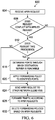
- FIG. 6 illustrates an example method 600 for configuring one or more network elements 108 for APBR in accordance with certain embodiments.
- an APBR request is received.
- the APBR request may be received from service appliance 104.
- the APBR request may include information indicating one or more forwarding policies to be applied at one or more network elements.
- a control channel of network element 108 is used to automate the task of creating the forwarding policies.
- Service appliance 104 as a function of its configuration, knows the IP address of the servers 116 in server farm 128, and may send this information to network element 108 in an APBR request.
- the APBR request may specify an IP address, port, and protocol of the destination server.
- step 608 it is determined whether the APBR request conflicts with any other APBR requests applied by the network element (or VDC thereof). For example, if an APBR request specifies the same destination server IP address, port, and protocol as an applied APBR request, then it may be considered to conflict with that APBR request. If there are no conflicting APBR requests, then the method moves to step 616. If there is a conflicting APBR request, then it is determined at step 612 whether the received APBR request takes precedence over the applied APBR request. Any suitable method may be used to determine which APBR request should take precedence.
- an APBR request received at a network element from a service appliance that is attached to that network element takes precedence over an APBR request received from another network element. If the received APBR request takes precedence, the method moves to step 616, otherwise the method will move to step 624.
- the ports through which the destination server 116 is reachable are determined.
- an ISCM of each VDC of a network element 108 may determine which of its ports may reach the destination server 116.
- a forwarding policy based on the APBR request is applied to each of the ports identified at step 616.
- this may involve creating an Access Control List (ACL) and an associated routemap.
- the ACL may have matching criteria comprising the protocol used by the server 116 to send packets, the IP address of the server 116, and the port of the server 116.
- the ACL will permit all traffic matching the criteria (such that it is not blocked by network element 108).
- the specified protocol in the ACL may include, by way of nonlimiting example, any L4 protocol such as TCP, UDP, or both TCP and UDP.
- a routemap may be associated with the ACL so as to set the nexthop IP for traffic matching the ACL criteria. This association may be stored in any suitable location, such as database 168.
- the next hop IP address is set to the IP address of the service appliance 104.
- the next hop IP address may be set to the IP address of an ISCM upstream from the second ISCM (e.g., the IP address of the first ISCM or a different ISCM between the first ISCM and the second ISCM).
- the routemap is then applied to all the ports of the network element 108 that are identified as being able to reach the destination server 116.
- the routemap is applied on each of the nexthop interfaces.
- the nexthop interface already has a route map assigned to it, a sequence to an existing routemap may be appended.
- the APBR request is forwarded to one or more other network elements 108 on the possible network paths to the destination server 116.
- These network elements may perform steps similar to those described above.
- data packets from the server 116 to client 120 are forwarded by the network element 108 at which the APBR request was implemented to the service appliance 104, which modifies the source address of the packets to match the address of the service appliance 104 and then sends the packets back through the network element 108 to the client 120.
- forwarding policies based on the APBR requests are deleted.
- various events may trigger an automatic purge of forwarding policies.
- forwarding policies may be purged in response to a server 116 becoming unavailable or in response to events associated with the service appliance, such as health monitoring failure, service appliance reboot, forced CLI or user-triggered shutdown of the service, or other suitable events.
- the routemap may be removed from the ports and the routemap and the ACL are deleted.
- the network element 108 may also instruct downstream network elements 108 to delete their forwarding policies associated with the service appliance and/or server 116.
- steps illustrated in FIG. 6 may be repeated, combined, modified or deleted where appropriate, and additional steps may also be included. Additionally, steps may be performed in any suitable order without departing from the scope of particular embodiments.
- FIG. 7 illustrates an example method 700 for configuring a communication server for a network in accordance with certain embodiments.
- ISCM instance identifiers are multicast among the ISCM instances of the network.
- a host ISCM instance is selected to host a communication server.
- the host ISCM share the configuration parameters of the communication server with the other ISCM instances. In alternative embodiments, this information may be shared during step 704 along with the ISCM instance identifiers.
- network configuration data may be communicated amongst the ISCMs via the communication server.
- APBR requests may be communicated from an ISCM coupled to a service appliance 104 to one or more of the other ISCMs in the network.
- heartbeat messages may be exchanged by the communication server at step 720. Based on these messages it may be determined at step 724 whether the communication server is still online. If the communication server is still online, the ISCMs may continue to communicate through the communication server to other ISCMs. If the communication server has gone offline, a different ISCM is selected to the host the communications server at step 708. Communications may then resume at step 716 through the new communications server.
- steps illustrated in FIG. 7 may be repeated, combined, modified or deleted where appropriate, and additional steps may also be included. Additionally, steps may be performed in any suitable order without departing from the scope of particular embodiments.
Landscapes
- Engineering & Computer Science (AREA)
- Computer Networks & Wireless Communication (AREA)
- Signal Processing (AREA)
- Data Exchanges In Wide-Area Networks (AREA)
Claims (12)
- Verfahren, das Folgendes umfasst:Empfangen, an einem Netzwerkelement, eines ersten Netzwerkverkehrs, der an eine erste Adresse gerichtet ist, die mit einem ersten Netzwerkknoten assoziiert ist;Weiterleiten des ersten Netzwerkverkehrs an den ersten Netzwerkknoten;Empfangen von dem ersten Netzwerkknoten des ersten Netzwerkverkehrs, der an eine zweite Adresse gerichtet ist, die mit einem zweiten Netzwerkknoten assoziiert ist, der mit dem Netzwerkelement gekoppelt ist, und einer Weiterleitungsrichtlinie für einen zweiten Netzwerkverkehr, wobei der zweite Netzwerkverkehr von dem zweiten Netzwerkknoten stammt;Identifizieren einer Vielzahl von Ports des Netzwerkelements, wobei der zweite Netzwerkknoten von dem Netzwerkelement durch jeden der Vielzahl von Ports zugreifbar ist;Weiterleiten des ersten Netzwerkverkehrs an den zweiten Netzwerkknoten über einen der Vielzahl von Ports;Konfigurieren der Vielzahl von Ports des Netzwerkelements, um die Weiterleitungsrichtlinie anzuwenden;Empfangen des zweiten Netzwerkverkehrs von dem zweiten Netzwerkknoten an einem der Vielzahl von Ports; undAnwenden der Weiterleitungsrichtlinie durch Weiterleiten des zweiten Netzwerkverkehrs an den ersten Netzwerkknoten.
- Verfahren nach Anspruch 1, wobei der erste Netzwerkknoten eine Service-Appliance ist, die zum Lastausgleich von Netzwerkverkehr unter einer Vielzahl von Servern betriebsfähig ist, und wobei der zweite Netzwerkknoten einer der Vielzahl von Servern ist.
- Verfahren nach Anspruch 1, wobei das Konfigurieren der Vielzahl von Ports des Netzwerkelements, um die Weiterleitungsrichtlinie anzuwenden, das Konfigurieren des Netzwerkelements umfasst, um eine Internetprotokolladresse der nächsten Teilstrecke zur ersten Adresse des ersten Netzwerkknotens zur Netzwerkverkehrszusammenpassung der Weiterleitungsrichtlinie festzulegen.
- Verfahren nach Anspruch 1, wobei ein erster Port der Vielzahl von Ports mit einem ersten virtuellen Gerätekontext des Netzwerkelements assoziiert ist und ein zweiter Port der Vielzahl von Ports mit einem zweiten virtuellen Gerätekontext des Netzwerkelements assoziiert ist.
- Verfahren nach Anspruch 4, das ferner das Speichern der Weiterleitungsrichtlinie in einer Datenbank umfasst, die von dem ersten virtuellen Gerätekontext des Netzwerkelements und dem zweiten virtuellen Gerätekontext des Netzwerkelements geteilt wird.
- Verfahren nach Anspruch 1, das ferner Folgendes umfasst:Bestimmen von mindestens einem zusätzlichen Netzwerkelement in einem Netzwerkpfad von dem Netzwerkelement zu dem zweiten Netzwerkknoten; undKommunizieren der Weiterleitungsrichtlinie an das mindestens eine zusätzliche Netzwerkelement.
- Verfahren nach Anspruch 6, wobei der zweite Netzwerkverkehr von dem mindestens einen zusätzlichen Netzwerkelement empfangen wird.
- Verfahren nach Anspruch 6, wobei das Kommunizieren der Weiterleitungsrichtlinie an das mindestens eine zusätzliche Netzwerkelement das Kommunizieren der Weiterleitungsrichtlinie an einen Kommunikationsserver umfasst, der von einem zweiten Netzwerkelement gehostet wird, zur Übertragung an das mindestens eine zusätzliche Netzwerkelement.
- Verfahren nach Anspruch 1, das ferner das Senden des ersten Netzwerkverkehrs von dem ersten Netzwerkknoten an den zweiten Netzwerkknoten von einem ersten Port der Vielzahl von Ports und das Empfangen des zweiten Netzwerkverkehrs an einem zweiten Port der Vielzahl von Ports umfasst.
- Verfahren nach Anspruch 1, wobei das Netzwerkelement ein Netzwerkschalter ist, der zum Überbrücken und Leitweglenken von Datenpaketen fähig ist.
- Vorrichtung, die Folgendes umfasst:
einen Prozessor, der konfiguriert ist, um ein Verfahren gemäß einem vorhergehenden Anspruch durchzuführen. - Mindestens ein computerlesbares, nicht transitorisches Medium, das eine oder mehrere Anweisungen umfasst, die, wenn sie von einem Prozessor ausgeführt werden, den Prozessor konfigurieren, um die Durchführung von Operationen zu bewirken, die ein Verfahren gemäß einem der Ansprüche 1 bis 10 umfassen.
Applications Claiming Priority (3)
| Application Number | Priority Date | Filing Date | Title |
|---|---|---|---|
| US201562161004P | 2015-05-13 | 2015-05-13 | |
| US14/835,435 US9935882B2 (en) | 2015-05-13 | 2015-08-25 | Configuration of network elements for automated policy-based routing |
| PCT/US2016/031652 WO2016183085A1 (en) | 2015-05-13 | 2016-05-10 | Configuration of network elements for automated policy-based routing |
Publications (2)
| Publication Number | Publication Date |
|---|---|
| EP3295654A1 EP3295654A1 (de) | 2018-03-21 |
| EP3295654B1 true EP3295654B1 (de) | 2020-07-08 |
Family
ID=56072437
Family Applications (1)
| Application Number | Title | Priority Date | Filing Date |
|---|---|---|---|
| EP16724790.7A Active EP3295654B1 (de) | 2015-05-13 | 2016-05-10 | Konfiguration von netzwerkelementen zur automatisierten richtlinienbasierten leitweglenkung |
Country Status (4)
| Country | Link |
|---|---|
| US (1) | US9935882B2 (de) |
| EP (1) | EP3295654B1 (de) |
| CN (1) | CN107624240B (de) |
| WO (1) | WO2016183085A1 (de) |
Families Citing this family (25)
| Publication number | Priority date | Publication date | Assignee | Title |
|---|---|---|---|---|
| CN104021069B (zh) * | 2013-02-28 | 2017-07-11 | 国际商业机器公司 | 基于分布式虚拟机系统的软件性能测试的管理方法和系统 |
| US9935834B1 (en) | 2015-03-13 | 2018-04-03 | Cisco Technology, Inc. | Automated configuration of virtual port channels |
| US10110668B1 (en) | 2015-03-31 | 2018-10-23 | Cisco Technology, Inc. | System and method for monitoring service nodes |
| US10305816B1 (en) | 2015-03-31 | 2019-05-28 | Cisco Technology, Inc. | Adjustable bit mask for high-speed native load balancing on a switch |
| US9954783B1 (en) | 2015-03-31 | 2018-04-24 | Cisco Technology, Inc. | System and method for minimizing disruption from failed service nodes |
| US10079725B1 (en) | 2015-04-01 | 2018-09-18 | Cisco Technology, Inc. | Route map policies for network switches |
| US9985894B1 (en) | 2015-04-01 | 2018-05-29 | Cisco Technology, Inc. | Exclude filter for load balancing switch |
| US10103995B1 (en) | 2015-04-01 | 2018-10-16 | Cisco Technology, Inc. | System and method for automated policy-based routing |
| US10075377B1 (en) | 2015-04-23 | 2018-09-11 | Cisco Technology, Inc. | Statistical collection in a network switch natively configured as a load balancer |
| US10033631B1 (en) | 2015-04-23 | 2018-07-24 | Cisco Technology, Inc. | Route distribution for service appliances |
| US10469389B1 (en) | 2015-04-23 | 2019-11-05 | Cisco Technology, Inc. | TCAM-based load balancing on a switch |
| CN105099789B (zh) * | 2015-09-02 | 2018-03-16 | 华为技术有限公司 | 一种网元升级方法及设备 |
| US10986039B2 (en) * | 2015-11-11 | 2021-04-20 | Gigamon Inc. | Traffic broker for routing data packets through sequences of in-line tools |
| US10848432B2 (en) | 2016-12-18 | 2020-11-24 | Cisco Technology, Inc. | Switch fabric based load balancing |
| US11082312B2 (en) | 2017-10-04 | 2021-08-03 | Cisco Technology, Inc. | Service chaining segmentation analytics |
| US10965596B2 (en) | 2017-10-04 | 2021-03-30 | Cisco Technology, Inc. | Hybrid services insertion |
| US10965598B1 (en) | 2017-10-04 | 2021-03-30 | Cisco Technology, Inc. | Load balancing in a service chain |
| US10778723B2 (en) | 2018-03-26 | 2020-09-15 | Forescout Technologies, Inc. | Device visibility and scanning including network segments |
| GB201905835D0 (en) * | 2019-04-26 | 2019-06-12 | Ibm | On-premise and off-premise debugging |
| CN110233713B (zh) * | 2019-06-26 | 2022-08-09 | 广东九博科技股份有限公司 | 一种基于lldp报文的多链路通信方法及系统 |
| US11683262B2 (en) | 2019-11-26 | 2023-06-20 | Cisco Technology, Inc. | Group-based policies for inter-domain traffic |
| US11528299B2 (en) * | 2020-05-06 | 2022-12-13 | Hewlett Packard Enterprise Development Lp | Method device and system for policy based packet processing |
| EP4173238B1 (de) * | 2020-06-24 | 2024-03-13 | Juniper Networks, Inc. | Punkt-zu-mehrpunkt-schicht-2-netzwerkerweiterung über ein schicht-3-netzwerk |
| US20250338047A1 (en) * | 2024-04-26 | 2025-10-30 | Dell Products L.P. | Managing network congestion using an optical link |
| CN119109659B (zh) * | 2024-09-05 | 2025-10-31 | 浪潮云信息技术股份公司 | 一种安全组的不连续端口规则的创建方法、装置及系统 |
Family Cites Families (49)
| Publication number | Priority date | Publication date | Assignee | Title |
|---|---|---|---|---|
| US6601084B1 (en) | 1997-12-19 | 2003-07-29 | Avaya Technology Corp. | Dynamic load balancer for multiple network servers |
| US6779039B1 (en) | 2000-03-31 | 2004-08-17 | Avaya Technology Corp. | System and method for routing message traffic using a cluster of routers sharing a single logical IP address distinct from unique IP addresses of the routers |
| US6996615B1 (en) | 2000-09-29 | 2006-02-07 | Cisco Technology, Inc. | Highly scalable least connections load balancing |
| US7184403B1 (en) | 2001-03-16 | 2007-02-27 | Cisco Technology, Inc. | Hardware load balancing through a single fabric |
| EP1315349B1 (de) | 2001-11-21 | 2008-03-19 | Sun Microsystems, Inc. | Verfahren um einen Lastverteiler in ein Client- Server- System zu integrieren |
| US7191235B1 (en) | 2002-11-26 | 2007-03-13 | Cisco Technology, Inc. | System and method for communicating data in a loadbalancing environment |
| US8239942B2 (en) | 2002-12-30 | 2012-08-07 | Cisco Technology, Inc. | Parallel intrusion detection sensors with load balancing for high speed networks |
| US7284053B1 (en) | 2003-03-31 | 2007-10-16 | Cisco Technology, Inc. | System and method for loadbalancing in a network environment |
| JP4336625B2 (ja) | 2004-06-17 | 2009-09-30 | 株式会社日立製作所 | パケット転送装置 |
| US7020090B2 (en) | 2004-06-21 | 2006-03-28 | Cisco Technology, Inc. | System and method for loadbalancing in a network environment using feedback information |
| US20060098573A1 (en) | 2004-11-08 | 2006-05-11 | Beer John C | System and method for the virtual aggregation of network links |
| US7623455B2 (en) | 2005-04-02 | 2009-11-24 | Cisco Technology, Inc. | Method and apparatus for dynamic load balancing over a network link bundle |
| US7340744B2 (en) | 2005-04-08 | 2008-03-04 | Cisco Technology, Inc. | System and method for optimizing sessions and network resources in a loadbalancing environment |
| US7694011B2 (en) | 2006-01-17 | 2010-04-06 | Cisco Technology, Inc. | Techniques for load balancing over a cluster of subscriber-aware application servers |
| US8004973B2 (en) * | 2006-04-25 | 2011-08-23 | Citrix Systems, Inc. | Virtual inline configuration for a network device |
| US8194664B2 (en) | 2006-10-10 | 2012-06-05 | Cisco Technology, Inc. | Two-level load-balancing of network traffic over an MPLS network |
| US8116310B2 (en) | 2007-11-24 | 2012-02-14 | Cisco Technology, Inc. | Reducing packet flooding by a packet switch |
| US7852774B2 (en) | 2007-11-28 | 2010-12-14 | Cisco Technology, Inc. | User datagram protocol traceroute probe extension |
| US8259722B1 (en) | 2008-05-19 | 2012-09-04 | Juniper Networks, Inc. | Integrated packet inspection and modification system and network device for internet service provider market research and influence |
| US9309539B2 (en) | 2009-04-10 | 2016-04-12 | Poet Research, Inc. | System for recycling water to facilitate the production of ethanol |
| CN101795235B (zh) * | 2010-03-18 | 2014-03-19 | 中兴通讯股份有限公司 | 一种路由映射的处理方法及运营商边界设备 |
| EP2553901B1 (de) | 2010-03-26 | 2016-04-27 | Citrix Systems, Inc. | System und verfahren zum linklastenausgleich in einer mehrkernvorrichtung |
| US8243598B2 (en) * | 2010-04-26 | 2012-08-14 | International Business Machines Corporation | Load-balancing via modulus distribution and TCP flow redirection due to server overload |
| US8937942B1 (en) | 2010-04-29 | 2015-01-20 | Juniper Networks, Inc. | Storing session information in network devices |
| US8499093B2 (en) | 2010-05-14 | 2013-07-30 | Extreme Networks, Inc. | Methods, systems, and computer readable media for stateless load balancing of network traffic flows |
| US8868726B1 (en) | 2010-07-02 | 2014-10-21 | Symantec Corporation | Systems and methods for performing backups |
| US20120163164A1 (en) | 2010-12-27 | 2012-06-28 | Brocade Communications Systems, Inc. | Method and system for remote load balancing in high-availability networks |
| CN103384989B (zh) | 2010-12-28 | 2016-06-22 | 思杰系统有限公司 | 用于对多个下一跳进行策略路由的系统和方法 |
| EP2482492A1 (de) | 2011-01-25 | 2012-08-01 | TeliaSonera AB | Messen der Dienstqualität |
| US8676980B2 (en) | 2011-03-22 | 2014-03-18 | Cisco Technology, Inc. | Distributed load balancer in a virtual machine environment |
| US20120303809A1 (en) | 2011-05-25 | 2012-11-29 | Microsoft Corporation | Offloading load balancing packet modification |
| CN107071088B (zh) | 2011-08-17 | 2020-06-05 | Nicira股份有限公司 | 逻辑l3路由 |
| CN102404229B (zh) * | 2011-12-14 | 2013-03-13 | 华为技术有限公司 | 负载均衡系统、装置及方法 |
| US8553552B2 (en) | 2012-02-08 | 2013-10-08 | Radisys Corporation | Stateless load balancer in a multi-node system for transparent processing with packet preservation |
| CN103259739A (zh) * | 2012-02-15 | 2013-08-21 | 株式会社日立制作所 | 负载均衡设备以及负载均衡方法 |
| US9648133B2 (en) | 2012-03-12 | 2017-05-09 | Telefonaktiebolaget L M Ericsson | Optimizing traffic load in a communications network |
| US10097452B2 (en) | 2012-04-16 | 2018-10-09 | Telefonaktiebolaget Lm Ericsson (Publ) | Chaining of inline services using software defined networking |
| CN102783099B (zh) * | 2012-05-15 | 2016-05-25 | 华为技术有限公司 | 控制业务传输的方法和装置 |
| US8848741B2 (en) | 2012-06-21 | 2014-09-30 | Breakingpoint Systems, Inc. | High-speed CLD-based TCP segmentation offload |
| US8805990B2 (en) | 2012-07-12 | 2014-08-12 | Microsoft Corporation | Load balancing for single-address tenants |
| US8904224B2 (en) | 2012-07-20 | 2014-12-02 | International Business Machines Corporation | Providing replication and fail-over as a network service in data centers |
| US9246998B2 (en) | 2012-10-16 | 2016-01-26 | Microsoft Technology Licensing, Llc | Load balancer bypass |
| US10547505B2 (en) * | 2013-03-01 | 2020-01-28 | Nokia Solutions And Networks Oy | Software defined networking for edge nodes |
| US9137156B2 (en) | 2013-04-24 | 2015-09-15 | Brocade Communications Systems, Inc. | Scalable and efficient flow-aware packet distribution |
| US9264400B1 (en) * | 2013-12-02 | 2016-02-16 | Trend Micro Incorporated | Software defined networking pipe for network traffic inspection |
| US20150188731A1 (en) * | 2013-12-27 | 2015-07-02 | Daniel P. Daly | Programmable Distributed Networking |
| CN103929368B (zh) * | 2014-05-05 | 2017-04-26 | 华为技术有限公司 | 多业务单元负载均衡方法及装置 |
| US20150326473A1 (en) * | 2014-05-09 | 2015-11-12 | Futurewei Technologies, Inc. | Service Chain Path Route Reservations |
| US9882815B2 (en) | 2014-12-22 | 2018-01-30 | Telefonaktiebolaget Lm Ericsson (Publ) | Adaptive load balancing in packet processing |
-
2015
- 2015-08-25 US US14/835,435 patent/US9935882B2/en active Active
-
2016
- 2016-05-10 CN CN201680027510.5A patent/CN107624240B/zh active Active
- 2016-05-10 EP EP16724790.7A patent/EP3295654B1/de active Active
- 2016-05-10 WO PCT/US2016/031652 patent/WO2016183085A1/en not_active Ceased
Non-Patent Citations (1)
| Title |
|---|
| None * |
Also Published As
| Publication number | Publication date |
|---|---|
| EP3295654A1 (de) | 2018-03-21 |
| US9935882B2 (en) | 2018-04-03 |
| US20160337244A1 (en) | 2016-11-17 |
| CN107624240B (zh) | 2020-10-16 |
| WO2016183085A1 (en) | 2016-11-17 |
| CN107624240A (zh) | 2018-01-23 |
Similar Documents
| Publication | Publication Date | Title |
|---|---|---|
| EP3295654B1 (de) | Konfiguration von netzwerkelementen zur automatisierten richtlinienbasierten leitweglenkung | |
| EP3222062B1 (de) | System und vorrichtung für kettenverteilte anwendungen in einer netzwerkumgebung | |
| EP3692685B1 (de) | Fernsteuerung von netzwerkslices in einem netzwerk | |
| US10397049B2 (en) | Auto-provisioning edge devices in a communication network using control plane communications | |
| US10116559B2 (en) | Operations, administration and management (OAM) in overlay data center environments | |
| US9331941B2 (en) | Traffic flow redirection between border routers using routing encapsulation | |
| EP3072264B1 (de) | Verfahren zur durchführung eines netzwerkdiensteinsatzes | |
| US11956141B2 (en) | Service chaining with physical network functions and virtualized network functions | |
| US9930149B2 (en) | Multicast traffic distribution in a multi-pod network environment | |
| US11792119B2 (en) | Multi-protocol service chaining among devices of interconnected topology | |
| US20220417323A1 (en) | In-band protocol-based in-network computation offload framework | |
| EP3917095A1 (de) | Verkettung von mehrfachprotokolldienst unter vorrichtung mit verbundener topologie | |
| US8675669B2 (en) | Policy homomorphic network extension | |
| US20210111925A1 (en) | Systems and methods for providing network connectors | |
| WO2019229760A1 (en) | Method and apparatus for optimized dissemination of layer 3 forwarding information in software defined networking (sdn) networks | |
| WO2018020447A1 (en) | Extending an mpls network using commodity network devices | |
| US12363030B2 (en) | Multi-protocol service chaining among devices of interconnected topology |
Legal Events
| Date | Code | Title | Description |
|---|---|---|---|
| STAA | Information on the status of an ep patent application or granted ep patent |
Free format text: STATUS: THE INTERNATIONAL PUBLICATION HAS BEEN MADE |
|
| PUAI | Public reference made under article 153(3) epc to a published international application that has entered the european phase |
Free format text: ORIGINAL CODE: 0009012 |
|
| STAA | Information on the status of an ep patent application or granted ep patent |
Free format text: STATUS: REQUEST FOR EXAMINATION WAS MADE |
|
| 17P | Request for examination filed |
Effective date: 20170831 |
|
| AK | Designated contracting states |
Kind code of ref document: A1 Designated state(s): AL AT BE BG CH CY CZ DE DK EE ES FI FR GB GR HR HU IE IS IT LI LT LU LV MC MK MT NL NO PL PT RO RS SE SI SK SM TR |
|
| AX | Request for extension of the european patent |
Extension state: BA ME |
|
| DAV | Request for validation of the european patent (deleted) | ||
| DAX | Request for extension of the european patent (deleted) | ||
| GRAP | Despatch of communication of intention to grant a patent |
Free format text: ORIGINAL CODE: EPIDOSNIGR1 |
|
| STAA | Information on the status of an ep patent application or granted ep patent |
Free format text: STATUS: GRANT OF PATENT IS INTENDED |
|
| INTG | Intention to grant announced |
Effective date: 20200107 |
|
| GRAS | Grant fee paid |
Free format text: ORIGINAL CODE: EPIDOSNIGR3 |
|
| GRAA | (expected) grant |
Free format text: ORIGINAL CODE: 0009210 |
|
| STAA | Information on the status of an ep patent application or granted ep patent |
Free format text: STATUS: THE PATENT HAS BEEN GRANTED |
|
| RAP1 | Party data changed (applicant data changed or rights of an application transferred) |
Owner name: CISCO TECHNOLOGY, INC. |
|
| AK | Designated contracting states |
Kind code of ref document: B1 Designated state(s): AL AT BE BG CH CY CZ DE DK EE ES FI FR GB GR HR HU IE IS IT LI LT LU LV MC MK MT NL NO PL PT RO RS SE SI SK SM TR |
|
| REG | Reference to a national code |
Ref country code: CH Ref legal event code: EP Ref country code: AT Ref legal event code: REF Ref document number: 1289715 Country of ref document: AT Kind code of ref document: T Effective date: 20200715 |
|
| REG | Reference to a national code |
Ref country code: DE Ref legal event code: R096 Ref document number: 602016039501 Country of ref document: DE |
|
| REG | Reference to a national code |
Ref country code: IE Ref legal event code: FG4D |
|
| REG | Reference to a national code |
Ref country code: LT Ref legal event code: MG4D |
|
| REG | Reference to a national code |
Ref country code: AT Ref legal event code: MK05 Ref document number: 1289715 Country of ref document: AT Kind code of ref document: T Effective date: 20200708 |
|
| REG | Reference to a national code |
Ref country code: NL Ref legal event code: MP Effective date: 20200708 |
|
| PG25 | Lapsed in a contracting state [announced via postgrant information from national office to epo] |
Ref country code: FI Free format text: LAPSE BECAUSE OF FAILURE TO SUBMIT A TRANSLATION OF THE DESCRIPTION OR TO PAY THE FEE WITHIN THE PRESCRIBED TIME-LIMIT Effective date: 20200708 Ref country code: HR Free format text: LAPSE BECAUSE OF FAILURE TO SUBMIT A TRANSLATION OF THE DESCRIPTION OR TO PAY THE FEE WITHIN THE PRESCRIBED TIME-LIMIT Effective date: 20200708 Ref country code: PT Free format text: LAPSE BECAUSE OF FAILURE TO SUBMIT A TRANSLATION OF THE DESCRIPTION OR TO PAY THE FEE WITHIN THE PRESCRIBED TIME-LIMIT Effective date: 20201109 Ref country code: ES Free format text: LAPSE BECAUSE OF FAILURE TO SUBMIT A TRANSLATION OF THE DESCRIPTION OR TO PAY THE FEE WITHIN THE PRESCRIBED TIME-LIMIT Effective date: 20200708 Ref country code: LT Free format text: LAPSE BECAUSE OF FAILURE TO SUBMIT A TRANSLATION OF THE DESCRIPTION OR TO PAY THE FEE WITHIN THE PRESCRIBED TIME-LIMIT Effective date: 20200708 Ref country code: GR Free format text: LAPSE BECAUSE OF FAILURE TO SUBMIT A TRANSLATION OF THE DESCRIPTION OR TO PAY THE FEE WITHIN THE PRESCRIBED TIME-LIMIT Effective date: 20201009 Ref country code: NO Free format text: LAPSE BECAUSE OF FAILURE TO SUBMIT A TRANSLATION OF THE DESCRIPTION OR TO PAY THE FEE WITHIN THE PRESCRIBED TIME-LIMIT Effective date: 20201008 Ref country code: BG Free format text: LAPSE BECAUSE OF FAILURE TO SUBMIT A TRANSLATION OF THE DESCRIPTION OR TO PAY THE FEE WITHIN THE PRESCRIBED TIME-LIMIT Effective date: 20201008 Ref country code: SE Free format text: LAPSE BECAUSE OF FAILURE TO SUBMIT A TRANSLATION OF THE DESCRIPTION OR TO PAY THE FEE WITHIN THE PRESCRIBED TIME-LIMIT Effective date: 20200708 Ref country code: AT Free format text: LAPSE BECAUSE OF FAILURE TO SUBMIT A TRANSLATION OF THE DESCRIPTION OR TO PAY THE FEE WITHIN THE PRESCRIBED TIME-LIMIT Effective date: 20200708 |
|
| PG25 | Lapsed in a contracting state [announced via postgrant information from national office to epo] |
Ref country code: RS Free format text: LAPSE BECAUSE OF FAILURE TO SUBMIT A TRANSLATION OF THE DESCRIPTION OR TO PAY THE FEE WITHIN THE PRESCRIBED TIME-LIMIT Effective date: 20200708 Ref country code: LV Free format text: LAPSE BECAUSE OF FAILURE TO SUBMIT A TRANSLATION OF THE DESCRIPTION OR TO PAY THE FEE WITHIN THE PRESCRIBED TIME-LIMIT Effective date: 20200708 Ref country code: PL Free format text: LAPSE BECAUSE OF FAILURE TO SUBMIT A TRANSLATION OF THE DESCRIPTION OR TO PAY THE FEE WITHIN THE PRESCRIBED TIME-LIMIT Effective date: 20200708 Ref country code: IS Free format text: LAPSE BECAUSE OF FAILURE TO SUBMIT A TRANSLATION OF THE DESCRIPTION OR TO PAY THE FEE WITHIN THE PRESCRIBED TIME-LIMIT Effective date: 20201108 |
|
| PG25 | Lapsed in a contracting state [announced via postgrant information from national office to epo] |
Ref country code: NL Free format text: LAPSE BECAUSE OF FAILURE TO SUBMIT A TRANSLATION OF THE DESCRIPTION OR TO PAY THE FEE WITHIN THE PRESCRIBED TIME-LIMIT Effective date: 20200708 |
|
| REG | Reference to a national code |
Ref country code: DE Ref legal event code: R097 Ref document number: 602016039501 Country of ref document: DE |
|
| PG25 | Lapsed in a contracting state [announced via postgrant information from national office to epo] |
Ref country code: CZ Free format text: LAPSE BECAUSE OF FAILURE TO SUBMIT A TRANSLATION OF THE DESCRIPTION OR TO PAY THE FEE WITHIN THE PRESCRIBED TIME-LIMIT Effective date: 20200708 Ref country code: DK Free format text: LAPSE BECAUSE OF FAILURE TO SUBMIT A TRANSLATION OF THE DESCRIPTION OR TO PAY THE FEE WITHIN THE PRESCRIBED TIME-LIMIT Effective date: 20200708 Ref country code: SM Free format text: LAPSE BECAUSE OF FAILURE TO SUBMIT A TRANSLATION OF THE DESCRIPTION OR TO PAY THE FEE WITHIN THE PRESCRIBED TIME-LIMIT Effective date: 20200708 Ref country code: RO Free format text: LAPSE BECAUSE OF FAILURE TO SUBMIT A TRANSLATION OF THE DESCRIPTION OR TO PAY THE FEE WITHIN THE PRESCRIBED TIME-LIMIT Effective date: 20200708 Ref country code: IT Free format text: LAPSE BECAUSE OF FAILURE TO SUBMIT A TRANSLATION OF THE DESCRIPTION OR TO PAY THE FEE WITHIN THE PRESCRIBED TIME-LIMIT Effective date: 20200708 Ref country code: EE Free format text: LAPSE BECAUSE OF FAILURE TO SUBMIT A TRANSLATION OF THE DESCRIPTION OR TO PAY THE FEE WITHIN THE PRESCRIBED TIME-LIMIT Effective date: 20200708 |
|
| PLBE | No opposition filed within time limit |
Free format text: ORIGINAL CODE: 0009261 |
|
| STAA | Information on the status of an ep patent application or granted ep patent |
Free format text: STATUS: NO OPPOSITION FILED WITHIN TIME LIMIT |
|
| PG25 | Lapsed in a contracting state [announced via postgrant information from national office to epo] |
Ref country code: AL Free format text: LAPSE BECAUSE OF FAILURE TO SUBMIT A TRANSLATION OF THE DESCRIPTION OR TO PAY THE FEE WITHIN THE PRESCRIBED TIME-LIMIT Effective date: 20200708 |
|
| 26N | No opposition filed |
Effective date: 20210409 |
|
| PG25 | Lapsed in a contracting state [announced via postgrant information from national office to epo] |
Ref country code: SK Free format text: LAPSE BECAUSE OF FAILURE TO SUBMIT A TRANSLATION OF THE DESCRIPTION OR TO PAY THE FEE WITHIN THE PRESCRIBED TIME-LIMIT Effective date: 20200708 |
|
| PG25 | Lapsed in a contracting state [announced via postgrant information from national office to epo] |
Ref country code: SI Free format text: LAPSE BECAUSE OF FAILURE TO SUBMIT A TRANSLATION OF THE DESCRIPTION OR TO PAY THE FEE WITHIN THE PRESCRIBED TIME-LIMIT Effective date: 20200708 |
|
| REG | Reference to a national code |
Ref country code: DE Ref legal event code: R079 Ref document number: 602016039501 Country of ref document: DE Free format text: PREVIOUS MAIN CLASS: H04L0029080000 Ipc: H04L0065000000 |
|
| REG | Reference to a national code |
Ref country code: CH Ref legal event code: PL |
|
| PG25 | Lapsed in a contracting state [announced via postgrant information from national office to epo] |
Ref country code: MC Free format text: LAPSE BECAUSE OF FAILURE TO SUBMIT A TRANSLATION OF THE DESCRIPTION OR TO PAY THE FEE WITHIN THE PRESCRIBED TIME-LIMIT Effective date: 20200708 Ref country code: LI Free format text: LAPSE BECAUSE OF NON-PAYMENT OF DUE FEES Effective date: 20210531 Ref country code: LU Free format text: LAPSE BECAUSE OF NON-PAYMENT OF DUE FEES Effective date: 20210510 Ref country code: CH Free format text: LAPSE BECAUSE OF NON-PAYMENT OF DUE FEES Effective date: 20210531 |
|
| REG | Reference to a national code |
Ref country code: BE Ref legal event code: MM Effective date: 20210531 |
|
| PG25 | Lapsed in a contracting state [announced via postgrant information from national office to epo] |
Ref country code: IE Free format text: LAPSE BECAUSE OF NON-PAYMENT OF DUE FEES Effective date: 20210510 |
|
| PG25 | Lapsed in a contracting state [announced via postgrant information from national office to epo] |
Ref country code: BE Free format text: LAPSE BECAUSE OF NON-PAYMENT OF DUE FEES Effective date: 20210531 |
|
| PG25 | Lapsed in a contracting state [announced via postgrant information from national office to epo] |
Ref country code: HU Free format text: LAPSE BECAUSE OF FAILURE TO SUBMIT A TRANSLATION OF THE DESCRIPTION OR TO PAY THE FEE WITHIN THE PRESCRIBED TIME-LIMIT; INVALID AB INITIO Effective date: 20160510 |
|
| PG25 | Lapsed in a contracting state [announced via postgrant information from national office to epo] |
Ref country code: CY Free format text: LAPSE BECAUSE OF FAILURE TO SUBMIT A TRANSLATION OF THE DESCRIPTION OR TO PAY THE FEE WITHIN THE PRESCRIBED TIME-LIMIT Effective date: 20200708 |
|
| P01 | Opt-out of the competence of the unified patent court (upc) registered |
Effective date: 20230525 |
|
| PG25 | Lapsed in a contracting state [announced via postgrant information from national office to epo] |
Ref country code: MK Free format text: LAPSE BECAUSE OF FAILURE TO SUBMIT A TRANSLATION OF THE DESCRIPTION OR TO PAY THE FEE WITHIN THE PRESCRIBED TIME-LIMIT Effective date: 20200708 |
|
| PG25 | Lapsed in a contracting state [announced via postgrant information from national office to epo] |
Ref country code: MT Free format text: LAPSE BECAUSE OF FAILURE TO SUBMIT A TRANSLATION OF THE DESCRIPTION OR TO PAY THE FEE WITHIN THE PRESCRIBED TIME-LIMIT Effective date: 20200708 |
|
| PGFP | Annual fee paid to national office [announced via postgrant information from national office to epo] |
Ref country code: DE Payment date: 20250422 Year of fee payment: 10 |
|
| PGFP | Annual fee paid to national office [announced via postgrant information from national office to epo] |
Ref country code: GB Payment date: 20250507 Year of fee payment: 10 |
|
| PGFP | Annual fee paid to national office [announced via postgrant information from national office to epo] |
Ref country code: FR Payment date: 20250505 Year of fee payment: 10 |
|
| PG25 | Lapsed in a contracting state [announced via postgrant information from national office to epo] |
Ref country code: TR Free format text: LAPSE BECAUSE OF FAILURE TO SUBMIT A TRANSLATION OF THE DESCRIPTION OR TO PAY THE FEE WITHIN THE PRESCRIBED TIME-LIMIT Effective date: 20200708 |