EP3295683B1 - Ensemble transducteur acoustique composé de transducteurs acoustiques mems - Google Patents
Ensemble transducteur acoustique composé de transducteurs acoustiques mems Download PDFInfo
- Publication number
- EP3295683B1 EP3295683B1 EP16721805.6A EP16721805A EP3295683B1 EP 3295683 B1 EP3295683 B1 EP 3295683B1 EP 16721805 A EP16721805 A EP 16721805A EP 3295683 B1 EP3295683 B1 EP 3295683B1
- Authority
- EP
- European Patent Office
- Prior art keywords
- substrate
- sound transducer
- mems
- cavity
- sound
- Prior art date
- Legal status (The legal status is an assumption and is not a legal conclusion. Google has not performed a legal analysis and makes no representation as to the accuracy of the status listed.)
- Active
Links
Images










Classifications
-
- H—ELECTRICITY
- H04—ELECTRIC COMMUNICATION TECHNIQUE
- H04R—LOUDSPEAKERS, MICROPHONES, GRAMOPHONE PICK-UPS OR LIKE ACOUSTIC ELECTROMECHANICAL TRANSDUCERS; ELECTRIC HEARING AIDS; PUBLIC ADDRESS SYSTEMS
- H04R19/00—Electrostatic transducers
- H04R19/04—Microphones
-
- H—ELECTRICITY
- H04—ELECTRIC COMMUNICATION TECHNIQUE
- H04R—LOUDSPEAKERS, MICROPHONES, GRAMOPHONE PICK-UPS OR LIKE ACOUSTIC ELECTROMECHANICAL TRANSDUCERS; ELECTRIC HEARING AIDS; PUBLIC ADDRESS SYSTEMS
- H04R1/00—Details of transducers, loudspeakers or microphones
- H04R1/02—Casings; Cabinets ; Supports therefor; Mountings therein
- H04R1/04—Structural association of microphone with electric circuitry therefor
-
- H—ELECTRICITY
- H04—ELECTRIC COMMUNICATION TECHNIQUE
- H04R—LOUDSPEAKERS, MICROPHONES, GRAMOPHONE PICK-UPS OR LIKE ACOUSTIC ELECTROMECHANICAL TRANSDUCERS; ELECTRIC HEARING AIDS; PUBLIC ADDRESS SYSTEMS
- H04R1/00—Details of transducers, loudspeakers or microphones
- H04R1/20—Arrangements for obtaining desired frequency or directional characteristics
- H04R1/22—Arrangements for obtaining desired frequency or directional characteristics for obtaining desired frequency characteristic only
- H04R1/24—Structural combinations of separate transducers or of two parts of the same transducer and responsive respectively to two or more frequency ranges
-
- H—ELECTRICITY
- H04—ELECTRIC COMMUNICATION TECHNIQUE
- H04R—LOUDSPEAKERS, MICROPHONES, GRAMOPHONE PICK-UPS OR LIKE ACOUSTIC ELECTROMECHANICAL TRANSDUCERS; ELECTRIC HEARING AIDS; PUBLIC ADDRESS SYSTEMS
- H04R1/00—Details of transducers, loudspeakers or microphones
- H04R1/20—Arrangements for obtaining desired frequency or directional characteristics
- H04R1/22—Arrangements for obtaining desired frequency or directional characteristics for obtaining desired frequency characteristic only
- H04R1/28—Transducer mountings or enclosures modified by provision of mechanical or acoustic impedances, e.g. resonator, damping means
-
- H—ELECTRICITY
- H04—ELECTRIC COMMUNICATION TECHNIQUE
- H04R—LOUDSPEAKERS, MICROPHONES, GRAMOPHONE PICK-UPS OR LIKE ACOUSTIC ELECTROMECHANICAL TRANSDUCERS; ELECTRIC HEARING AIDS; PUBLIC ADDRESS SYSTEMS
- H04R17/00—Piezoelectric transducers; Electrostrictive transducers
-
- H—ELECTRICITY
- H04—ELECTRIC COMMUNICATION TECHNIQUE
- H04R—LOUDSPEAKERS, MICROPHONES, GRAMOPHONE PICK-UPS OR LIKE ACOUSTIC ELECTROMECHANICAL TRANSDUCERS; ELECTRIC HEARING AIDS; PUBLIC ADDRESS SYSTEMS
- H04R19/00—Electrostatic transducers
-
- H—ELECTRICITY
- H04—ELECTRIC COMMUNICATION TECHNIQUE
- H04R—LOUDSPEAKERS, MICROPHONES, GRAMOPHONE PICK-UPS OR LIKE ACOUSTIC ELECTROMECHANICAL TRANSDUCERS; ELECTRIC HEARING AIDS; PUBLIC ADDRESS SYSTEMS
- H04R19/00—Electrostatic transducers
- H04R19/005—Electrostatic transducers using semiconductor materials
-
- H—ELECTRICITY
- H04—ELECTRIC COMMUNICATION TECHNIQUE
- H04R—LOUDSPEAKERS, MICROPHONES, GRAMOPHONE PICK-UPS OR LIKE ACOUSTIC ELECTROMECHANICAL TRANSDUCERS; ELECTRIC HEARING AIDS; PUBLIC ADDRESS SYSTEMS
- H04R1/00—Details of transducers, loudspeakers or microphones
- H04R1/20—Arrangements for obtaining desired frequency or directional characteristics
- H04R1/22—Arrangements for obtaining desired frequency or directional characteristics for obtaining desired frequency characteristic only
- H04R1/28—Transducer mountings or enclosures modified by provision of mechanical or acoustic impedances, e.g. resonator, damping means
- H04R1/2869—Reduction of undesired resonances, i.e. standing waves within enclosure, or of undesired vibrations, i.e. of the enclosure itself
- H04R1/2876—Reduction of undesired resonances, i.e. standing waves within enclosure, or of undesired vibrations, i.e. of the enclosure itself by means of damping material, e.g. as cladding
-
- H—ELECTRICITY
- H04—ELECTRIC COMMUNICATION TECHNIQUE
- H04R—LOUDSPEAKERS, MICROPHONES, GRAMOPHONE PICK-UPS OR LIKE ACOUSTIC ELECTROMECHANICAL TRANSDUCERS; ELECTRIC HEARING AIDS; PUBLIC ADDRESS SYSTEMS
- H04R1/00—Details of transducers, loudspeakers or microphones
- H04R1/20—Arrangements for obtaining desired frequency or directional characteristics
- H04R1/22—Arrangements for obtaining desired frequency or directional characteristics for obtaining desired frequency characteristic only
- H04R1/28—Transducer mountings or enclosures modified by provision of mechanical or acoustic impedances, e.g. resonator, damping means
- H04R1/2869—Reduction of undesired resonances, i.e. standing waves within enclosure, or of undesired vibrations, i.e. of the enclosure itself
- H04R1/2884—Reduction of undesired resonances, i.e. standing waves within enclosure, or of undesired vibrations, i.e. of the enclosure itself by means of the enclosure structure, i.e. strengthening or shape of the enclosure
-
- H—ELECTRICITY
- H04—ELECTRIC COMMUNICATION TECHNIQUE
- H04R—LOUDSPEAKERS, MICROPHONES, GRAMOPHONE PICK-UPS OR LIKE ACOUSTIC ELECTROMECHANICAL TRANSDUCERS; ELECTRIC HEARING AIDS; PUBLIC ADDRESS SYSTEMS
- H04R2201/00—Details of transducers, loudspeakers or microphones covered by H04R1/00 but not provided for in any of its subgroups
- H04R2201/003—Mems transducers or their use
Definitions
- the present invention relates to a sound transducer arrangement having a first and a second MEMS sound transducer for generating and/or detecting sound waves in the audible wavelength spectrum, each comprising a cavity, and having an ASIC electrically connected to the first MEMS sound transducer.
- Such sound transducer arrangements can have very small dimensions and are therefore installed as loudspeakers and/or microphones, for example, in hearing aids, in-ear headphones, mobile phones, tablet computers and other electronic devices that only offer little installation space.
- MEMS microelectromechanical systems.
- a MEMS transducer for sound generation or a MEMS speaker is for example from DE 10 2012 220 819 A1 famous. The sound is generated via an oscillating membrane of the MEMS loudspeaker.
- Such sound transducer arrangements are constructed specifically according to the acoustic and other requirements of the respective area of application and consist of a large number of different elements.
- a major disadvantage of such sound transducer arrangements is that their manufacture is correspondingly complex, time-consuming and costly.
- a sound transducer arrangement which comprises a first substrate with a switching element and a second substrate with a microphone chip.
- the two substrates are connected to one another in an electrically conductive manner.
- a surface mount microphone package that includes a first microphone and a second microphone. Furthermore, the surface-mount microphone package includes a first opening for the first microphone and a second opening for the second microphone. The first opening and the second opening are located on opposite sides of the surface mount microphone package.
- An acoustic transducer arrangement is proposed with a first MEMS acoustic transducer, which includes a first cavity, and with an ASIC that is electrically connected to the first MEMS acoustic transducer.
- the MEMS sound transducer is a microelectromechanical system for generating and/or detecting sound waves in the audible wavelength spectrum.
- the MEMS sound transducer is preferably driven electromechanically, electrostatically and/or piezoelectrically.
- the ASIC is an electronic application-specific integrated circuit suitable for operating the MEMS transducer.
- cavity is to be understood as meaning a cavity by means of which the sound pressure of the MEMS sound transducer can be amplified.
- the ASIC is embedded in a first substrate while the first MEMS transducer is disposed on a second substrate.
- the first substrate with the integrated ASIC and the second substrate with the at least partially integrated MEMS sound transducer thus represent two separate components, ie components manufactured separately from one another.
- the first and the second substrate are connected to one another. They thus have a common connection area in which they are in direct contact with one another.
- the connection between the two substrates is preferably by material connection produced, these are preferably glued together. In addition or as an alternative, however, the connection can also be made by means of a form fit and/or force fit.
- the two substrates are connected to one another in such a way that the ASIC and the first MEMS sound transducer are electrically conductively coupled or connected to one another.
- a certain amount of rejects is inevitable in the production of sound transducer arrangements.
- the additional costs arising from rejects can be reduced by initially producing the substrates separately from one another. Thereafter, the functionality of their respective at least one electronic component, i.e. the ASIC or the MEMS sound transducer, is checked. Only after a positive check of their functionality - i.e. when it is ensured that the ASIC and/or the MEMS sound transducer has not been damaged during the respective integration or embedding process - are they connected to each other, in particular glued. In this way it can be ensured that only two functional substrates are connected to one another to form a sound transducer arrangement.
- the proposed sound transducer arrangement offers many advantages. If the ASIC is completely integrated into the first substrate and the first cavity is formed at least partially in the second substrate, the sound transducer arrangement can be formed in a very space-saving manner. It is advantageous if the first cavity is additionally formed in the first substrate.
- the sound transducer arrangement can be manufactured much more efficiently.
- the individual modules which either comprise a first substrate and an ASIC (hereinafter referred to as ASIC module for short) or a second substrate and a MEMS sound transducer (hereinafter referred to as MEMS module for short), can be produced, tested and tested independently of one another in respective sub-processes be temporarily stored if necessary. Each of these sub-processes can be specifically optimized.
- the design of the ASIC module and the MEMS module can also be specifically optimized.
- Connecting an ASIC module and a MEMS module can take place late in the manufacturing process.
- This connection can take place in particular by soldering, conductive adhesive and/or in another suitable manner, so that the first and the second substrate are at least electrically and preferably also positively, non-positively and/or cohesively connected to one another.
- the ASIC modules and/or the MEMS modules can also be manufactured in different variants and then combined to form different sound transducer arrangements, for example by combining different MEMS module variants with an ASIC module variant or a MEMS module variant can be combined with different ASIC module variants. This enables the flexible design of an extensive product family of different sound transducer arrangements while at the same time exploiting economies of scale.
- connection between the two modules or between the first and the second substrate are designed to be detachable, so that later in the event of repairs only the defective one of the two modules has to be replaced with a new module.
- the first cavity is at least partially formed in the second substrate. As a result, a particularly large volume of the cavity can be achieved. It is advantageous if the first cavity is additionally formed in the first substrate.
- a second MEMS sound transducer is arranged on a third substrate.
- the first substrate and the third substrate are electrically connected to one another.
- such an acoustic transducer arrangement comprises the first substrate with the ASIC, the second substrate with the first MEMS acoustic transducer and the third substrate with the second MEMS acoustic transducer.
- the first substrate is arranged between the second substrate and the third substrate.
- the second MEMS sound transducer also includes a cavity, this second cavity being formed at least partially in the third substrate and advantageously additionally in the first substrate.
- the modular design of the sound transducer arrangement thus advantageously enables the ASIC module to be connected to a further MEMS module, which comprises a third substrate and a second MEMS sound transducer.
- This connection can also take place in particular by soldering, conductive adhesive and/or in another suitable manner, so that the first and the second substrate are at least electrically and preferably also positively, non-positively and/or cohesively connected to one another.
- the two MEMS modules can essentially be designed with the same or different characteristic properties.
- the acoustic transducer arrangement equipped with two MEMS modules usually has a better performance, in particular in the form of a greater bandwidth and/or greater sound pressure, than if it were equipped with only a single MEMS module.
- the two cavities of the MEMS sound transducers are separated from one another by an intermediate wall of the first substrate, with the two cavities thus not influencing one another.
- the intermediate wall preferably has at least one connection opening extending from the first cavity to the second cavity, so that there is a flow connection between the two cavities and the volume of one cavity is increased by the volume of the other cavity.
- the partition wall has at least one stiffening element, in particular in the form of a rib, which stabilizes the partition wall and thus prevents, or at least significantly reduces, deformation and/or oscillation of the partition wall.
- the two cavities preferably have volumes of different sizes.
- the cavity volume can be a characteristic in which the MEMS modules differ.
- the substrates namely the first, second and third substrate, are each designed as a circuit board or PCB (printed circuit board) and/or are produced using PCB technology.
- PCB printed circuit board
- the first, second and third substrates are each a PCB substrate, ie a printed circuit board that is made up of one or preferably multiple layers, the multiple layers being arranged on top of one another in the manner of a sandwich and/or being connected to one another, preferably with a material bond.
- the first substrate can have a recess for the integrative accommodation of the ASIC, which is designed, for example, as a printed circuit board cavity with a sufficiently large volume that the ASIC can be arranged or embedded therein.
- further components in particular passive components such as electrical resistors and/or I/O contacts, can also be embedded in and/or arranged on the first substrate.
- the housing part and/or the sound-conducting element preferably consist of a material that is different from the substrate, in particular a plastic and/or metal.
- the substrates are manufactured separately from one another.
- the ASIC is embedded or encapsulated in the production of the first substrate.
- the ASIC and/or additional active and/or passive electronic components are fully integrated in the first substrate.
- the second substrate is manufactured separately together with the MEMS sound transducer.
- the MEMS sound transducer can be fastened, for example, on one side of the second substrate, in particular in a materially bonded manner.
- the MEMS sound transducer can also be connected to the second substrate in a form-fitting manner.
- a frame of the MEMS sound transducer is encompassed by the second substrate in a form-fitting manner.
- the membrane can vibrate freely.
- the first module comprising the ASIC and the first substrate and/or the second module comprising the MEMS sound transducer and the second substrate -
- they are connected to one another in a subsequent manufacturing step, in particular glued .
- the functionality the module can be checked before its final connection, so that the scrap and consequently the manufacturing costs can be reduced.
- the Figures 1 to 3 show a first exemplary embodiment of a sound transducer arrangement 1, which is not covered by the claimed invention, in different views.
- the sound transducer arrangement 1 essentially comprises a first substrate 10 designed as a printed circuit board with an ASIC 11 and a second substrate 20 designed as a printed circuit board with a MEMS sound transducer 21.
- the MEMS sound transducer 21 is provided with electrical contacts that are not shown in detail in the figures connected to the ASIC 11.
- the MEMS sound transducer 21 can thus be controlled or operated via the ASIC 11 .
- the sound transducer arrangement 1 has an essentially rectangular basic shape. Having a rectangular basic shape, the sound transducer arrangement can be produced easily and inexpensively and is suitable for numerous application purposes. Alternatively, however, the sound transducer arrangement can in principle also have a different basic shape, in particular a round shape.
- the MEMS sound transducer 21 is designed in such a way that it can generate and/or detect sound waves in the audible wavelength spectrum.
- the MEMS sound transducer 21 comprises, in addition to a MEMS actuator 22, as additional, in particular acoustic, components, a membrane 23, a membrane plate 24 and a membrane frame 25.
- the membrane 23, which is made of rubber, for example, is fixed in its edge area connected to the membrane frame 25, while it is firmly connected to the membrane plate 24, in particular in its middle region, the membrane plate 24 itself not being connected to the membrane frame 25.
- the membrane 23 thus spans the membrane frame 25 and is reinforced by the membrane plate 24 in particular in its central region. If the MEMS transducer 21 is to act as a speaker, for example, it can be excited via the ASIC 11 in such a way that the MEMS actuator 22, the membrane 23 for generating sound energy relative to the membrane frame 25 is vibrated.
- the second substrate 20 carries the MEMS actuator 22 and the membrane frame 25 with the membrane 23 attached thereto, the MEMS actuator 22 being arranged below the membrane 23, and the second substrate 20 below the membrane 23 and the MEMS actuator 22 has a cavity 29 .
- the cavity 29 is laterally surrounded or delimited by walls 27 of the second substrate 20, while it is closed at the top by the membrane 23.
- the cavity 29 is closed at the bottom by the first substrate 10 to which the second substrate 20 is connected.
- the cavity 29 thus forms the cavity 41 of the MEMS sound transducer 21, which is used in particular to increase the sound pressure of the MEMS sound transducer 21.
- the membrane frame 25 has essentially the same outer diameter as the second substrate 20, while the MEMS actuator 22 has a smaller outer diameter than the substrate 20.
- the essentially opposing wall sections 27a of the second substrate 20 are thicker than the wall sections 27b of the second substrate 20, the thicker wall sections 27a projecting into the cavity 29 compared to the wall sections 27b.
- the MEMS actuator 22 only rests on the projections 28 formed by the wall sections 27a, while the membrane frame 25 rests, in particular over the entire circumference, on both the wall sections 27a and 27b.
- the MEMS actuator 22 is surrounded by the membrane frame 25 on the side.
- the MEMS sound transducer 21 and in particular the MEMS actuator 22 and/or the membrane frame 25 can be glued to the second substrate 20 be. Furthermore, the second substrate 20 can be glued to the first substrate 10 .
- the sound transducer arrangement 1 has at least one pressure equalization channel 70, which in this exemplary embodiment comprises an equalization opening 26, which is preferably not on one of the thick wall sections 27, but on one of the thin wall portions 27 of the second substrate 20 is arranged.
- air can flow out of the cavity 41 formed by the hollow space 29 through the pressure equalization channel 70 when the membrane 23 is lowered. In an analogous manner, however, air can also flow into the cavity 41 via the pressure compensation channel 70 when the membrane 23 is lifted.
- the first substrate 10 has a cavity 13a which is essentially completely closed.
- the ASIC 11 is arranged in the cavity 13a.
- the ASIC 11 is thus completely embedded in the first substrate 10 .
- the sound transducer arrangement 1 has electrical, in particular passive, additional components 12a, 12b, such as electrical resistors and/or I/O contacts. These additional components 12a, 12b are also embedded in the first substrate 10, being arranged in the further cavity 13b of the substrate 10, which is also essentially completely closed.
- the additional electronic components 12a, 12b could also be arranged together with the ASIC 11 in the cavity 13a.
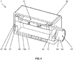
- the Figures 4 to 6 show a second embodiment of the sound transducer arrangement 1, which is not covered by the claimed invention, in different views.
- a housing part 50 is additionally provided in the second exemplary embodiment of the sound transducer arrangement 1 .
- this housing part 50 offers protection for the MEMS sound transducer 21.
- the housing part 50 has a cavity 53 in which the second substrate 20 and the MEMS sound transducer 21 are essentially completely received, and which extends downwards from the first substrate 10 is closed, with which the housing part 50 is connected.
- the housing part 50 also has an acoustic inlet/outlet opening 51 which is arranged laterally on the outer surface 55 of the housing part and thus also on the sound transducer arrangement.
- the housing part 50 is connected to the first substrate 10 and in particular also dimensioned such that at least a first section 62 of a sound-conducting channel 61 is formed between the housing part 50 and the second substrate 20 with the MEMS sound transducer 21 .
- a second section 63 of the sound-conducting channel 61 is formed in the housing part 50 itself.
- the housing part 50 has a tubular projection 52 in the area of the acoustic inlet/outlet opening 51 .
- the sound conduction channel 61 is at least partially formed in that the cavity 53 of the housing part 50 is not completely filled by the second substrate 20 and the MEMS sound transducer 21 .
- Sound can be directed and/or amplified by means of the sound conduction channel 61 from the MEMS sound transducer 21 to the acoustic entry/exit opening 51 and/or vice versa.
- the acoustic inlet/outlet opening 51 can be positioned essentially anywhere on the outer surface 55 or another outer surface of the sound transducer arrangement 1, in particular on an installation-oriented upper side and/or on a side surface.
- the housing part 50 also has an acoustic equalization opening 56 which is arranged laterally on the outer surface 58 of the housing part 50 .
- the equalization opening 56 corresponds to the equalization opening 26 and, like this, belongs to the pressure equalization channel 70 of the sound transducer arrangement 1.
- the equalization opening 56 has a larger diameter than the equalization opening 26. This means that no dirt and/or liquid can enter the cavity through the pressure equalization channel 70 41, the compensation opening 56 is covered with an elastic closure element 57 in this example.
- the pressure equalization functionality is nevertheless ensured since the elastic closure element 57 can deform according to the pressure prevailing in the cavity 41 .
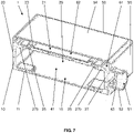
- the Figures 7 to 9 show a third exemplary embodiment of the sound transducer arrangement 1, which is not covered by the claimed invention, in different views.
- the cavity 41 is in each case partially formed by a hollow space in the first and second substrate 10, 20.
- the membrane frame 25 has essentially the same outer diameter as the MEMS actuator 22, with this outer diameter being smaller than the outer diameter of the second substrate 20.
- the second substrate 20 carries the MEMS actuator 22 and the membrane frame 25 with the membrane 23 attached thereto, with the MEMS actuator 22 being arranged below the membrane 23 and with the second substrate 20 below the membrane 23 and the MEMS actuator 22 has the cavity 29 which is closed at the top by the membrane 23.
- the cavity 29 of the second substrate 20 is open at the bottom and borders on the cavity 15 of the first substrate 10, which is open at the top.
- the cavities 15 and 29 have the same diameter and the lower free ends of the walls 27 correspond to the upper free ends of the walls 16.
- the walls 16 of the first substrate 10 are connected to the walls 27 of the second substrate 20 connected and in particular glued, the cavity 15 of the first substrate and the cavity 29 of the second substrate being arranged one above the other and then together forming the cavity 41 for the MEMS sound transducer 21 .
- a pressure compensation channel 70 is not shown in the figures for this example, but can preferably be provided.
- the housing part 50 is very economical in this example and, in addition to the outer surface 55 on which the acoustic inlet/outlet opening 51 with the tubular projection 52 is arranged, essentially only has one further outer surface 54, which in particular provides protection for the MEMS transducer 21 provides.
- the housing part 50 is nevertheless connected to the first substrate 10 and the second substrate 20 in such a way that at least a first section 62 of a sound duct 61 is formed between the housing part 50 and the second substrate 20 with the MEMS sound transducer 21 and the first substrate 10.
- the second section 63 of the sound-conducting channel 61 is formed in the housing part 50 itself and in particular by the tubular projection 52 .
- the sound-conducting element 64 is provided with a concave sound-conducting edge 65 in this example, which is arranged between the housing part 50 and the first and second substrate within the sound-conducting channel 61 . More precisely, the sound-conducting element 64 is arranged in the transition area between the first and second sections 62, 63 of the sound-conducting channel 61.
- the sound-conducting element is designed here as a single component. Alternatively, however, it can also be formed on the housing part 50 and/or on a substrate.
- the sound-conducting element 64 is particularly in the Figures 8 and 9 clearly visible.
- the figure 8 shows the sound transducer arrangement 1 of the third exemplary embodiment in an exploded view.
- the other components of the sound transducer arrangement 1 such as the ASIC 11, the substrates 10 and 20 and, above all, the MEMS actuator 22, the membrane 23 on the membrane frame 25 and the membrane plate 24 very recognizable.
- the housing part 50 is shown semi-transparent, so that the protected components of the sound transducer arrangement 1 located behind it can still be clearly seen.
- the figure 10 shows a fourth exemplary embodiment of the sound transducer arrangement 1, which is not covered by the claimed invention.
- the cavity 41 is at least approximately completely filled with a porous material 5.
- the figure 11 shows a fifth exemplary embodiment of the sound transducer arrangement 1 not covered by the claimed invention.
- the cavity 41 is at least almost completely filled with a porous material 5.
- the filling of the cavity 41 of the MEMS sound transducer 21 causes an effective increase in the surface area within the cavity and a virtual increase in the volume of the cavity, as a result of which greater sound pressure and better bass reproduction can be achieved.
- the figure 12 shows a sixth exemplary embodiment of the sound transducer arrangement 1 that is not covered by the claimed invention.
- This is a purely schematic representation of the sound transducer arrangement 1, which comprises a first substrate 10 with an ASIC 11 and a second substrate 20 with a MEMS sound transducer 21, however has no housing. Only the MEMS actuator 22 of the MEMS sound transducer 21 is shown here.
- Both the first substrate 10 and the second substrate 20 have conductor tracks 7 for electrically connecting the individual components, such as ASIC 11 and MEMS actuator 21 in particular.
- the conductor tracks 7 of the first substrate 10 are connected to the conductor tracks 7 of the second substrate 20 by means of soldered connections 8 or electrically conductive adhesive 8 .
- the two substrates 10, 20 can also be connected to one another in other ways in a form-fitting, force-fitting and/or cohesive manner.
- the second substrate 20 has a cavity 29 which is surrounded or delimited at the side by walls 27 of the second substrate 20 and is closed off at the bottom by the first substrate 10 .
- the walls 27 have wall sections 27a projecting into the cavity 29, which provide a support 28 for the MEMS actuator 22, which has a smaller outer diameter than the second substrate 20.
- the cavity 29 is closed at the top by the additional acoustic components of the MEMS sound transducer that belong to the MEMS actuator 22 but are not shown here.
- the cavity 29 thus forms the cavity 41 of the MEMS sound transducer.
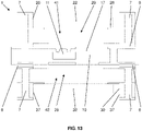
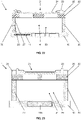
- the figure 13 shows a seventh embodiment of the sound transducer arrangement 1.
- the sound transducer arrangement 1 of this seventh exemplary embodiment also includes a third substrate 30 with a second MEMS sound transducer, of which here only the MEMS actuator 32 is shown.
- the first substrate 10 is arranged between the second substrate 20 and the third substrate 30 .
- the third substrate 30 with the second MEMS actuator 32 is constructed essentially like the second substrate 20 with the first MEMS actuator 22, but the third substrate 30 is arranged rotated by 180° compared to the second substrate 20.
- the third substrate 30 therefore also has conductor tracks 7 for the electrical connection of the individual components.
- the conductor tracks 7 of the third substrate 30 are also connected to the conductor tracks 7 of the first substrate by means of soldered connections 8 or electrically conductive adhesive 8 .
- the two substrates 10, 30 can also be connected to one another in another way in a form-fitting, force-fitting and/or cohesive manner.
- the third substrate 30 has a cavity 39 which is laterally surrounded or delimited by the walls 37 of the third substrate 30 and is closed at the top by the first substrate 10 .
- the hollow space 39 is closed at the bottom by the further acoustic components of the second MEMS sound transducer 31 which belong to the second MEMS actuator 32 but are not shown here.
- the cavity 39 thus forms the second cavity 42 of the second MEMS sound transducer.
- the first and the second cavity 41, 42 are formed separately, but essentially with the same characteristic properties such as, for example, dimensions and volume.
- the two cavities 41, 42 are separated from one another by an intermediate wall 17, which is provided by the first substrate 10, so that the two cavities 41, 42 do not affect one another.
- the intermediate wall can also have at least one connection opening extending from the first cavity 41 to the second cavity 42, which is not shown here, however. This connection opening then enables a flow connection between the two cavities, so that the volume of one cavity is increased by the volume of the other cavity in each case.
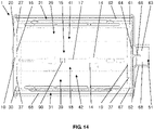
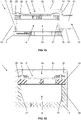
- the figure 14 shows an eighth exemplary embodiment of the sound transducer arrangement 1.
- the sound transducer arrangement 1 of this eighth exemplary embodiment additionally includes a third substrate 30 with a second MEMS sound transducer 31.
- the first substrate 10 is arranged between the second substrate 20 and the third substrate 30 .
- the third substrate 30 with the second MEMS sound transducer 31 is constructed essentially like the second substrate 20 with the first MEMS sound transducer 21, but the third substrate 30 is arranged turned by 180° compared to the second substrate 20.
- the first substrate 10 has a cavity 18 on its underside, which is delimited laterally by walls 19 of the first substrate and is closed at the top by the first substrate 10 .
- the cavity 18 is open at the bottom and borders on the cavity 39 of the third substrate 30, which is open at the top.
- the cavity 39 is laterally surrounded or delimited by the walls 37 of the third substrate 30 and at the bottom by the membrane 33 of the second MEMS sound transducer 31 closed.
- the cavities 18 and 39 have the same diameter and the lower free ends of the walls 19 correspond to the upper free ends of the walls 37.
- the walls 19 of the first substrate 10 are connected to the walls 37 of the third substrate 30 connected and in particular glued, the cavity 18 of the first substrate and the cavity 39 of the third substrate being arranged one above the other and then together forming the cavity 42 for the MEMS sound transducer 31 .
- the first and second cavities 41, 42 in this eighth exemplary embodiment have different characteristic properties and, in particular, different dimensions and different cavity volumes. This is essentially solely due to the fact that the walls 16 on the upper side of the first substrate 10 are higher than the walls 19 on the underside of the first substrate 10.
- the first and second MEMS sound transducers 21, 31 will already reveal a different sound behavior due to the differently designed cavities 41, 42, even under otherwise identical conditions.
- the sound behavior of the two MEMS sound transducers can also be influenced in a targeted manner, for example, by specifically designing the membranes 23, 33 and/or the MEMS actuators 22, 32.
- one of the MEMS transducers can act as a woofer and the other MEMS transducer can act as a tweeter, so that a sound transducer arrangement equipped in this way can generate sound in a larger bandwidth than, for example, a sound transducer arrangement according to the third exemplary embodiment.
- the intermediate wall 17 provided by the first substrate 10, which separates the two cavities 41, 42 from one another, has four stiffening elements 14, which are designed as ribs and serve to stabilize the intermediate wall 17. Deformation and/or vibration of the intermediate wall 17, in particular during operation of the sound transducer arrangement 1, can be significantly reduced or even prevented as a result.
- the intermediate wall 17 has at least one connection opening 90 .
- the connection opening 90 connects the two cavities 41, 42 to one another.
- the housing part 50 is designed very sparingly, as in the third exemplary embodiment, and in addition to the outer surface 55, on which the acoustic inlet/outlet opening 51 with the tubular projection 52 is arranged, essentially only has the other outer surfaces 54a and 54b, which offer protection for the first MEMS sound transducer 21 and the second MEMS sound transducer 31 in particular.
- the housing part 50 is also connected to the first substrate 10, the second substrate 20 and the third substrate 30 in such a way that a first and a second sound-conducting channel 61, 67 are formed. At least a first section 62 of the first sound-conducting channel 61 is located between the housing part 50 and in particular the second substrate 20 with the MEMS sound transducer 21, and at least a first section 68 of the second sound-conducting channel 67 is formed.
- acoustic inlet/outlet opening 51 is also provided in this sound transducer arrangement 1 .
- the second section 63 of the first sound-conducting channel 61 and the second section 69 of the second sound-conducting channel 67 are therefore formed as a common section, which in this example is also formed in the housing part 50 itself and in particular by the tubular projection 52 in the area of the acoustic inlet/outlet opening 51 is.
- the sound-conducting element 64 is also provided in this example to further improve the sound conduction and in particular to focus the sound.
- the sound-conducting element 64 is designed and arranged in such a way that it separates the first section 62 of the first sound-conducting channel 61 from the first section 68 of the second sound-conducting channel 67 .
- the sound-conducting element 64 has an extension 66 projecting into the common second section.
- the sound-conducting element 64 has two concave sound-conducting edges 65a and 65b in this example, with the sound-conducting edge 65a being assigned to the first sound-conducting channel 61 and the sound-conducting edge 65b being assigned to the second sound-conducting channel 67 .
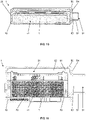
- the Figures 15 to 17 show a ninth exemplary embodiment of the sound transducer arrangement 1, which is not covered by the claimed invention, in different views.
- an additional substrate 80 is provided in the ninth exemplary embodiment of the sound transducer arrangement 1 .
- membrane frame 25 has essentially the same outside diameter as second substrate 20
- MEMS actuator 22 has a smaller outside diameter than substrate 20
- the walls 27 of the second substrate 20, which laterally delimit the cavity 29 of the second substrate 20 have no wall sections projecting into the cavity 29 that could serve as a support for the MEMS actuator 22.
- the additional substrate 80 which has essentially the same outer diameter as the second substrate 20.
- the additional substrate 80 has a cavity 89 which is delimited laterally by walls 87 of the substrate 80, the walls 87 having a significantly lower height than the walls 27 of the second substrate 20.
- the substantially opposing wall sections 87a of the substrate 80 are thicker than the wall sections 87b of the substrate 80, the thicker wall sections 87a projecting into the cavity 89 in relation to the wall sections 87b.
- the MEMS actuator 22 then rests on the projections 88 formed by the wall sections 87a, while the membrane frame 25 rests, in particular over the entire circumference, both on the wall sections 87a and 87b.
- the MEMS actuator 22 is arranged below the membrane 23 and surrounded by the membrane frame 25 on the side.
- the cavity 89 is thus closed by the membrane 23 at the top.
- the cavity 89 is open at the bottom and borders on the cavity 29 of the second substrate 20, which is open at the top and is closed by the first substrate 10 at the bottom.
- the cavities 29 and 89 arranged one above the other then together form the cavity 41 for the MEMS sound transducer 21. Since the walls 27 of the second substrate 20 do not have any wall sections projecting into the cavity 29, which would reduce the cavity 29, this contributes to increasing the through the cavity 29 with the cavity 41 formed.
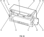
- the Figures 18 to 20 show a tenth exemplary embodiment of the sound transducer arrangement 1, which is not covered by the claimed invention, in different views.
- a housing part 50 is additionally provided in the tenth exemplary embodiment of the sound transducer arrangement 1, which is essentially as in FIG the second embodiment is formed.
- the additional substrate 80 is also accommodated in the cavity 53 of the housing part 50 in the tenth exemplary embodiment of the sound transducer arrangement 1 .
- the Figures 21 to 23 show an eleventh exemplary embodiment of the sound transducer arrangement 1, which is not covered by the claimed invention, in different views.
- the eleventh exemplary embodiment of the sound transducer arrangement 1 the second substrate 20, the MEMS actuator 22 and the membrane frame 25 of the first MEMS sound transducer 21 each have the same outside diameter.
- the walls 27 of the second substrate 20, which laterally delimit the cavity 29 of the second substrate 20, have no wall sections projecting into the cavity 29 that would have to serve as a support for the MEMS actuator 22. Rather, the MEMS actuator 22 preferably rests on the walls 27 of the second substrate 20 over its entire circumference, with the membrane frame 25 also resting on the outer edge region of the MEMS actuator 22 .
- the second substrate 20 carries the MEMS actuator 22 and the membrane frame 25 with the membrane 23 attached thereto, with the MEMS actuator 22 being arranged below the membrane 23, and with the second substrate 20 below the membrane 23 and of the MEMS actuator 22 has the cavity 29 which is closed at the top by the membrane 23.
- the cavity 29 of the second substrate 20 is closed by the first substrate 10 at the bottom.
- the cavity 41 of the MEMS sound transducer 21 formed by the hollow space 29 could be enlarged effectively and at the same time in a very space-saving manner.
- the Figures 24 to 26 show a twelfth exemplary embodiment of the sound transducer arrangement 1, which is not covered by the claimed invention, in different views.
- a housing part 50 is additionally provided in the twelfth exemplary embodiment of the sound transducer arrangement 1, which is designed essentially as in the second exemplary embodiment.
Landscapes
- Physics & Mathematics (AREA)
- Engineering & Computer Science (AREA)
- Acoustics & Sound (AREA)
- Signal Processing (AREA)
- Health & Medical Sciences (AREA)
- Otolaryngology (AREA)
- Electrostatic, Electromagnetic, Magneto- Strictive, And Variable-Resistance Transducers (AREA)
- Details Of Audible-Bandwidth Transducers (AREA)
Claims (5)
- Ensemble de transducteur acoustique (1),avec un premier substrat (10),avec un premier et un deuxième transducteurs acoustiques MEMS (21, 31) destinés à générer et/ou à détecter des ondes acoustiques dans le spectre de longueurs d'onde audibles, qui comprennent chacun une cavité (41, 42), etavec un circuit intégré à application spécifique (ASIC) (11) électriquement relié avec le premier transducteur acoustique MEMS (21),dans lequel les deux cavités (41, 42) des transducteurs acoustiques MEMS (21, 31) sont séparées l'une de l'autre par une paroi intermédiaire (17) du premier substrat (10),caractérisé en ce quel'ASIC (11) est incorporé dans le premier substrat (10) ;le premier transducteur acoustique MEMS (21) est disposé sur un deuxième substrat (20) de sorte que la cavité (41) du premier transducteur acoustique MEMS (21) est formée au moins partiellement dans le deuxième substrat (20), un espace creux (29) du deuxième substrat (20), formant cette cavité (41), étant entouré ou limité latéralement par des parois (27) du deuxième substrat (20), tandis qu'il est fermé vers le haut par une membrane (23) du premier transducteur acoustique MEMS (21) ;le premier substrat (10) et le deuxième substrat (20) sont reliés l'un à l'autre sorte que l'ASIC (11) du premier substrat (10) et le premier transducteur acoustique MEMS (21) du deuxième substrat (20) sont couplés électriquement l'un à l'autre ;le deuxième transducteur acoustique MEMS (31) est disposé sur un troisième substrat (30) de sorte que la cavité (42) du deuxième transducteur acoustique MEMS (31) est formée au moins partiellement dans le troisième substrat (30), un espace creux (39) du troisième substrat (30), formant cette cavité (42), étant entouré ou limité latéralement par des parois (37) du troisième substrat (30) et étant fermé vers le bas par une membrane (33) du deuxième transducteur acoustique MEMS (31) ;le premier substrat (10) et le troisième substrat (30) sont reliés l'un à l'autre de manière électroconductrice ;le premier substrat (10) est disposé entre le deuxième substrat (20) et le troisième substrat (30) ; etles substrats (10, 20, 30) sont réalisés chacun sous forme de carte imprimé ou PCB (carte de circuits imprimés).
- Ensemble de transducteur acoustique selon la revendication 1 précédente, caractérisé en ce que
la cavité (41, 42) du premier et/ou du deuxième transducteur acoustique MEMS (21, 31) est formée de surcroît dans le premier substrat (10). - Ensemble de transducteur acoustique selon l'une quelconque ou plusieurs des revendications précédentes, caractérisé en ce que la paroi intermédiaire (17) présente au moins une ouverture de communication (90) et/ou un canal de communication s'étendant de la cavité (41) du premier transducteur acoustique MEMS (21) à la cavité (42) du deuxième transducteur acoustique MEMS (31).
- Ensemble de transducteur acoustique selon l'une quelconque ou plusieurs des revendications précédentes, caractérisé en ce que la paroi intermédiaire (17) présente au moins un élément raidisseur (14), en particulier une nervure.
- Ensemble de transducteur acoustique selon l'une quelconque ou plusieurs des revendications précédentes, caractérisé en ce que les deux cavités (41, 42) de l'ensemble de transducteur acoustique (1 ) présentent des volumes différents.
Applications Claiming Priority (2)
| Application Number | Priority Date | Filing Date | Title |
|---|---|---|---|
| DE102015107560.1A DE102015107560A1 (de) | 2015-05-13 | 2015-05-13 | Schallwandleranordnung mit MEMS-Schallwandler |
| PCT/EP2016/060426 WO2016180820A1 (fr) | 2015-05-13 | 2016-05-10 | Ensemble transducteur acoustique composé d'un transducteur acoustique mems |
Publications (2)
| Publication Number | Publication Date |
|---|---|
| EP3295683A1 EP3295683A1 (fr) | 2018-03-21 |
| EP3295683B1 true EP3295683B1 (fr) | 2022-05-04 |
Family
ID=55963359
Family Applications (1)
| Application Number | Title | Priority Date | Filing Date |
|---|---|---|---|
| EP16721805.6A Active EP3295683B1 (fr) | 2015-05-13 | 2016-05-10 | Ensemble transducteur acoustique composé de transducteurs acoustiques mems |
Country Status (9)
| Country | Link |
|---|---|
| US (1) | US10412505B2 (fr) |
| EP (1) | EP3295683B1 (fr) |
| KR (1) | KR20180014726A (fr) |
| CN (1) | CN107864696B (fr) |
| AU (1) | AU2016261293B2 (fr) |
| CA (1) | CA2985721A1 (fr) |
| DE (1) | DE102015107560A1 (fr) |
| SG (2) | SG11201709249VA (fr) |
| WO (1) | WO2016180820A1 (fr) |
Families Citing this family (20)
| Publication number | Priority date | Publication date | Assignee | Title |
|---|---|---|---|---|
| DK3279621T4 (da) | 2016-08-26 | 2025-04-28 | Sonion Nederland Bv | Vibrationssensor med lavfrekvent roll-off-responskurve |
| DE102017108594A1 (de) * | 2017-04-21 | 2018-10-25 | USound GmbH | Lautsprechereinheit mit einem elektrodynamischen und einem MEMS-Lautsprecher |
| DE102017114008A1 (de) | 2017-06-23 | 2018-12-27 | USound GmbH | In-Ohr Hörer |
| DE102017114142A1 (de) | 2017-06-26 | 2018-12-27 | USound GmbH | Schallwandleranordnung mit einer MEMS-Einheit |
| JP7410935B2 (ja) | 2018-05-24 | 2024-01-10 | ザ リサーチ ファウンデーション フォー ザ ステイト ユニバーシティー オブ ニューヨーク | 容量性センサ |
| EP3651479B1 (fr) * | 2018-11-08 | 2022-06-01 | Usound GmbH | Procédé de fabrication d'au moins une unité membrane d'un transducteur mems |
| DE102019101325A1 (de) * | 2019-01-17 | 2020-07-23 | USound GmbH | Herstellungsverfahren für mehrere MEMS-Schallwandler |
| US11805342B2 (en) | 2019-09-22 | 2023-10-31 | xMEMS Labs, Inc. | Sound producing package structure and manufacturing method thereof |
| CN110677788B (zh) * | 2019-09-24 | 2021-01-15 | 维沃移动通信有限公司 | 一种发声模组及电子设备 |
| JP6857271B1 (ja) * | 2019-10-14 | 2021-04-14 | シャープ株式会社 | スピーカ装置及び表示装置 |
| US11395073B2 (en) * | 2020-04-18 | 2022-07-19 | xMEMS Labs, Inc. | Sound producing package structure and method for packaging sound producing package structure |
| CN121099230A (zh) | 2020-03-31 | 2025-12-09 | 深圳市韶音科技有限公司 | 声学输出设备 |
| WO2021223886A1 (fr) * | 2020-05-08 | 2021-11-11 | Fraunhofer-Gesellschaft zur Förderung der angewandten Forschung e.V. | Microsystème électromécanique (mems) destiné à interagir avec un flux volumétrique de façon hautement efficace |
| CN111918188B (zh) * | 2020-07-10 | 2021-12-14 | 瑞声科技(南京)有限公司 | 一种mems扬声器及其制造工艺 |
| US20230403513A1 (en) * | 2020-10-26 | 2023-12-14 | Tohoku University | Electrostatic transducer and method of manufacturing electrostatic transducer |
| DE102021133329A1 (de) | 2021-12-03 | 2023-06-07 | USound GmbH | MEMS-Schallwandler mit einer Dämpfungsschicht aus Klebstoff |
| CN116233710A (zh) | 2021-12-03 | 2023-06-06 | 悠声股份有限公司 | 具有由胶粘剂制成的阻尼层的mems音频转换器 |
| CN114125675A (zh) * | 2021-12-21 | 2022-03-01 | 歌尔微电子股份有限公司 | Mems器件、麦克风及电子产品 |
| JP2024158341A (ja) | 2023-04-27 | 2024-11-08 | ミツミ電機株式会社 | 振動デバイス、スピーカユニット、及び振動デバイスの製造方法 |
| SE548176C2 (en) * | 2023-06-22 | 2026-04-13 | Myvox Ab | A mems-based sound producing device and system and a method of manufacturing a mems-based sound producing device |
Citations (3)
| Publication number | Priority date | Publication date | Assignee | Title |
|---|---|---|---|---|
| US20050018864A1 (en) * | 2000-11-28 | 2005-01-27 | Knowles Electronics, Llc | Silicon condenser microphone and manufacturing method |
| US20070047746A1 (en) * | 2005-08-23 | 2007-03-01 | Analog Devices, Inc. | Multi-Microphone System |
| DE102014214153A1 (de) * | 2013-07-22 | 2015-02-26 | Infineon Technologies Ag | oberflächenmontierbares Mikrofonpackage, Mikrofonanordnung, Mobiltelefon und Verfahren zum Aufzeichnen von Mikrofonsignalen |
Family Cites Families (25)
| Publication number | Priority date | Publication date | Assignee | Title |
|---|---|---|---|---|
| US3953675A (en) * | 1972-05-08 | 1976-04-27 | Babbco, Ltd. | Audio speaker system |
| DE10053326A1 (de) * | 2000-10-27 | 2002-05-08 | Bosch Gmbh Robert | Mikromechanisches Bauelement und Herstellungsverfahren |
| US6675932B2 (en) * | 2001-07-02 | 2004-01-13 | Harman International Industries, Inc. | Speaker housing configured to minimize standing waves and resonate above the frequency range of transducers |
| US6588544B2 (en) * | 2001-08-06 | 2003-07-08 | Joseph C. Fox | Speaker box with molded plastic end caps |
| WO2009014015A1 (fr) * | 2007-07-20 | 2009-01-29 | Kuraray Chemical Co., Ltd. | Matériau pour dispositif haut-parleur et dispositif haut-parleur l'utilisant |
| JP2010187076A (ja) * | 2009-02-10 | 2010-08-26 | Funai Electric Co Ltd | マイクロホンユニット |
| US8292023B2 (en) * | 2009-02-13 | 2012-10-23 | Nokia Corporation | Enclosing adsorbent material |
| US8885863B2 (en) | 2009-05-19 | 2014-11-11 | Visionarist Co., Ltd. | Loudspeaker device |
| JP5691181B2 (ja) * | 2010-01-27 | 2015-04-01 | 船井電機株式会社 | マイクロホンユニット、及び、それを備えた音声入力装置 |
| US8577063B2 (en) * | 2010-02-18 | 2013-11-05 | Analog Devices, Inc. | Packages and methods for packaging MEMS microphone devices |
| JP5029727B2 (ja) * | 2010-06-01 | 2012-09-19 | オムロン株式会社 | 半導体装置及びマイクロフォン |
| US9407997B2 (en) * | 2010-10-12 | 2016-08-02 | Invensense, Inc. | Microphone package with embedded ASIC |
| JP4893860B1 (ja) * | 2011-02-21 | 2012-03-07 | オムロン株式会社 | マイクロフォン |
| US8804982B2 (en) * | 2011-04-02 | 2014-08-12 | Harman International Industries, Inc. | Dual cell MEMS assembly |
| US8969980B2 (en) * | 2011-09-23 | 2015-03-03 | Knowles Electronics, Llc | Vented MEMS apparatus and method of manufacture |
| US9402137B2 (en) | 2011-11-14 | 2016-07-26 | Infineon Technologies Ag | Sound transducer with interdigitated first and second sets of comb fingers |
| DE102011086722A1 (de) | 2011-11-21 | 2013-05-23 | Robert Bosch Gmbh | Mikromechanische Funktionsvorrichtung, insbesondere Lautsprechervorrichtung, und entsprechendes Herstellungsverfahren |
| US8995694B2 (en) * | 2012-02-01 | 2015-03-31 | Knowles Electronics, Llc | Embedded circuit in a MEMS device |
| DE102012020819A1 (de) | 2012-10-23 | 2014-05-08 | Liebherr-Werk Biberach Gmbh | Kran |
| US9006845B2 (en) | 2013-01-16 | 2015-04-14 | Infineon Technologies, A.G. | MEMS device with polymer layer, system of a MEMS device with a polymer layer, method of making a MEMS device with a polymer layer |
| US9332330B2 (en) | 2013-07-22 | 2016-05-03 | Infineon Technologies Ag | Surface mountable microphone package, a microphone arrangement, a mobile phone and a method for recording microphone signals |
| DE102013214823A1 (de) * | 2013-07-30 | 2015-02-05 | Robert Bosch Gmbh | Mikrofonbauteil mit mindestens zwei MEMS-Mikrofonbauelementen |
| DE102014203881A1 (de) * | 2014-03-04 | 2015-09-10 | Robert Bosch Gmbh | Bauteil mit Mikrofon- und Mediensensorfunktion |
| DE102014105754B4 (de) | 2014-04-24 | 2022-02-10 | USound GmbH | Lautsprecheranordnung mit leiterplattenintegriertem ASIC |
| DE102014211190A1 (de) * | 2014-06-12 | 2015-12-17 | Robert Bosch Gmbh | Mikromechanische Schallwandleranordnung und ein entsprechendes Herstellungsverfahren |
-
2015
- 2015-05-13 DE DE102015107560.1A patent/DE102015107560A1/de not_active Withdrawn
-
2016
- 2016-05-10 SG SG11201709249VA patent/SG11201709249VA/en unknown
- 2016-05-10 CN CN201680027830.0A patent/CN107864696B/zh active Active
- 2016-05-10 SG SG10201909786Q patent/SG10201909786QA/en unknown
- 2016-05-10 KR KR1020177035938A patent/KR20180014726A/ko not_active Ceased
- 2016-05-10 CA CA2985721A patent/CA2985721A1/fr not_active Abandoned
- 2016-05-10 AU AU2016261293A patent/AU2016261293B2/en not_active Ceased
- 2016-05-10 EP EP16721805.6A patent/EP3295683B1/fr active Active
- 2016-05-10 WO PCT/EP2016/060426 patent/WO2016180820A1/fr not_active Ceased
- 2016-05-10 US US15/572,825 patent/US10412505B2/en active Active
Patent Citations (3)
| Publication number | Priority date | Publication date | Assignee | Title |
|---|---|---|---|---|
| US20050018864A1 (en) * | 2000-11-28 | 2005-01-27 | Knowles Electronics, Llc | Silicon condenser microphone and manufacturing method |
| US20070047746A1 (en) * | 2005-08-23 | 2007-03-01 | Analog Devices, Inc. | Multi-Microphone System |
| DE102014214153A1 (de) * | 2013-07-22 | 2015-02-26 | Infineon Technologies Ag | oberflächenmontierbares Mikrofonpackage, Mikrofonanordnung, Mobiltelefon und Verfahren zum Aufzeichnen von Mikrofonsignalen |
Also Published As
| Publication number | Publication date |
|---|---|
| DE102015107560A1 (de) | 2016-11-17 |
| HK1247015A1 (zh) | 2018-09-14 |
| KR20180014726A (ko) | 2018-02-09 |
| SG11201709249VA (en) | 2017-12-28 |
| AU2016261293A1 (en) | 2017-12-14 |
| CN107864696B (zh) | 2021-02-02 |
| CA2985721A1 (fr) | 2016-11-17 |
| EP3295683A1 (fr) | 2018-03-21 |
| US10412505B2 (en) | 2019-09-10 |
| WO2016180820A1 (fr) | 2016-11-17 |
| CN107864696A (zh) | 2018-03-30 |
| SG10201909786QA (en) | 2019-11-28 |
| US20180139543A1 (en) | 2018-05-17 |
| AU2016261293B2 (en) | 2020-12-10 |
Similar Documents
| Publication | Publication Date | Title |
|---|---|---|
| EP3295683B1 (fr) | Ensemble transducteur acoustique composé de transducteurs acoustiques mems | |
| EP3143778B1 (fr) | Transducteur acoustique mems ainsi que système de transducteur acoustique équipé d'un mécanisme d'arrêt | |
| EP3381202B1 (fr) | Unité carte de circuit imprimé mems souple et ensemble transducteur acoustique | |
| DE102014105754B4 (de) | Lautsprecheranordnung mit leiterplattenintegriertem ASIC | |
| EP2282558B1 (fr) | Dispositif auditif et procédé | |
| EP3590271A1 (fr) | Unité haut-parleur dotée d'un haut-parleur électrodynamique et d'un haut-parleur mems | |
| DE102014100464B4 (de) | Multi-MEMS-Modul | |
| DE102010040370B4 (de) | MEMS-Mikrofon-Package | |
| EP3320694A1 (fr) | Module à carte de circuit imprimé mems à structure piézoélectrique intégrée et ensemble transducteur acoustique | |
| DE102008053327A1 (de) | Anordnung mit einem Mikrofon | |
| DE3525724A1 (de) | Piezoelektrischer elektroakustischer wandler | |
| DE102010062149A1 (de) | MEMS-Mikrophonhäusung und MEMS-Mikrophonmodul | |
| WO2007054071A1 (fr) | Microphone a systeme mecanique microelectrique (mems), procede de production correspondant et procede de montage approprie | |
| DE19839978A1 (de) | Tonmeßgeber und dessen Herstellverfahren sowie Halbleiter-Elektret-Kondensatorenmikrophon mit dem drin eingebauten Tonmeßgeber | |
| DE102019125815A1 (de) | Schallwandlereinheit zum Erzeugen und/oder Erfassen von Schallwellen im hörbaren Wellenlängenbereich und/oder im Ultraschallbereich | |
| DE102015107557A1 (de) | Leiterplattenmodul mit durchgehender Aussparung sowie diesbezügliche Schallwandleranordnung sowie Herstellungsverfahren | |
| WO2015161940A1 (fr) | Microphone à volume arrière majoré et procédé de fabrication | |
| EP1259095A2 (fr) | Microphone électrostatique | |
| EP3739904B1 (fr) | Système de transducteur acoustique et dispositif acoustique | |
| DE112010006098T5 (de) | Package mit einem unter einem MEMS-Chip angeordneten CMOS-Chip | |
| WO2019001930A1 (fr) | Ensemble transducteur acoustique comprenant une unité mems | |
| DE102005031601B4 (de) | Kapazitives, mikromechanisches Mikrofon | |
| DE202022100478U1 (de) | MEMS-Schallwandler mit Elektronikeinheit | |
| DE102015226483A1 (de) | Mikrofon und Verfahren zum Herstellen desselben | |
| DE202022100037U1 (de) | MEMS-Schallwandler mit einer verstärkten Membran |
Legal Events
| Date | Code | Title | Description |
|---|---|---|---|
| STAA | Information on the status of an ep patent application or granted ep patent |
Free format text: STATUS: THE INTERNATIONAL PUBLICATION HAS BEEN MADE |
|
| PUAI | Public reference made under article 153(3) epc to a published international application that has entered the european phase |
Free format text: ORIGINAL CODE: 0009012 |
|
| STAA | Information on the status of an ep patent application or granted ep patent |
Free format text: STATUS: REQUEST FOR EXAMINATION WAS MADE |
|
| 17P | Request for examination filed |
Effective date: 20171114 |
|
| AK | Designated contracting states |
Kind code of ref document: A1 Designated state(s): AL AT BE BG CH CY CZ DE DK EE ES FI FR GB GR HR HU IE IS IT LI LT LU LV MC MK MT NL NO PL PT RO RS SE SI SK SM TR |
|
| AX | Request for extension of the european patent |
Extension state: BA ME |
|
| DAV | Request for validation of the european patent (deleted) | ||
| DAX | Request for extension of the european patent (deleted) | ||
| RIN1 | Information on inventor provided before grant (corrected) |
Inventor name: RUSCONI CLERICI BELTRAMI, ANDREA Inventor name: BOTTONI, FERRUCCIO |
|
| STAA | Information on the status of an ep patent application or granted ep patent |
Free format text: STATUS: EXAMINATION IS IN PROGRESS |
|
| 17Q | First examination report despatched |
Effective date: 20190618 |
|
| GRAP | Despatch of communication of intention to grant a patent |
Free format text: ORIGINAL CODE: EPIDOSNIGR1 |
|
| STAA | Information on the status of an ep patent application or granted ep patent |
Free format text: STATUS: GRANT OF PATENT IS INTENDED |
|
| INTG | Intention to grant announced |
Effective date: 20211115 |
|
| GRAS | Grant fee paid |
Free format text: ORIGINAL CODE: EPIDOSNIGR3 |
|
| GRAA | (expected) grant |
Free format text: ORIGINAL CODE: 0009210 |
|
| STAA | Information on the status of an ep patent application or granted ep patent |
Free format text: STATUS: THE PATENT HAS BEEN GRANTED |
|
| AK | Designated contracting states |
Kind code of ref document: B1 Designated state(s): AL AT BE BG CH CY CZ DE DK EE ES FI FR GB GR HR HU IE IS IT LI LT LU LV MC MK MT NL NO PL PT RO RS SE SI SK SM TR |
|
| REG | Reference to a national code |
Ref country code: GB Ref legal event code: FG4D Free format text: NOT ENGLISH |
|
| REG | Reference to a national code |
Ref country code: CH Ref legal event code: EP |
|
| REG | Reference to a national code |
Ref country code: AT Ref legal event code: REF Ref document number: 1490430 Country of ref document: AT Kind code of ref document: T Effective date: 20220515 |
|
| REG | Reference to a national code |
Ref country code: DE Ref legal event code: R096 Ref document number: 502016014841 Country of ref document: DE |
|
| REG | Reference to a national code |
Ref country code: IE Ref legal event code: FG4D Free format text: LANGUAGE OF EP DOCUMENT: GERMAN |
|
| REG | Reference to a national code |
Ref country code: LT Ref legal event code: MG9D |
|
| REG | Reference to a national code |
Ref country code: NL Ref legal event code: MP Effective date: 20220504 |
|
| PG25 | Lapsed in a contracting state [announced via postgrant information from national office to epo] |
Ref country code: SE Free format text: LAPSE BECAUSE OF FAILURE TO SUBMIT A TRANSLATION OF THE DESCRIPTION OR TO PAY THE FEE WITHIN THE PRESCRIBED TIME-LIMIT Effective date: 20220504 Ref country code: PT Free format text: LAPSE BECAUSE OF FAILURE TO SUBMIT A TRANSLATION OF THE DESCRIPTION OR TO PAY THE FEE WITHIN THE PRESCRIBED TIME-LIMIT Effective date: 20220905 Ref country code: NO Free format text: LAPSE BECAUSE OF FAILURE TO SUBMIT A TRANSLATION OF THE DESCRIPTION OR TO PAY THE FEE WITHIN THE PRESCRIBED TIME-LIMIT Effective date: 20220804 Ref country code: NL Free format text: LAPSE BECAUSE OF FAILURE TO SUBMIT A TRANSLATION OF THE DESCRIPTION OR TO PAY THE FEE WITHIN THE PRESCRIBED TIME-LIMIT Effective date: 20220504 Ref country code: LT Free format text: LAPSE BECAUSE OF FAILURE TO SUBMIT A TRANSLATION OF THE DESCRIPTION OR TO PAY THE FEE WITHIN THE PRESCRIBED TIME-LIMIT Effective date: 20220504 Ref country code: HR Free format text: LAPSE BECAUSE OF FAILURE TO SUBMIT A TRANSLATION OF THE DESCRIPTION OR TO PAY THE FEE WITHIN THE PRESCRIBED TIME-LIMIT Effective date: 20220504 Ref country code: GR Free format text: LAPSE BECAUSE OF FAILURE TO SUBMIT A TRANSLATION OF THE DESCRIPTION OR TO PAY THE FEE WITHIN THE PRESCRIBED TIME-LIMIT Effective date: 20220805 Ref country code: FI Free format text: LAPSE BECAUSE OF FAILURE TO SUBMIT A TRANSLATION OF THE DESCRIPTION OR TO PAY THE FEE WITHIN THE PRESCRIBED TIME-LIMIT Effective date: 20220504 Ref country code: ES Free format text: LAPSE BECAUSE OF FAILURE TO SUBMIT A TRANSLATION OF THE DESCRIPTION OR TO PAY THE FEE WITHIN THE PRESCRIBED TIME-LIMIT Effective date: 20220504 Ref country code: BG Free format text: LAPSE BECAUSE OF FAILURE TO SUBMIT A TRANSLATION OF THE DESCRIPTION OR TO PAY THE FEE WITHIN THE PRESCRIBED TIME-LIMIT Effective date: 20220804 |
|
| PG25 | Lapsed in a contracting state [announced via postgrant information from national office to epo] |
Ref country code: RS Free format text: LAPSE BECAUSE OF FAILURE TO SUBMIT A TRANSLATION OF THE DESCRIPTION OR TO PAY THE FEE WITHIN THE PRESCRIBED TIME-LIMIT Effective date: 20220504 Ref country code: PL Free format text: LAPSE BECAUSE OF FAILURE TO SUBMIT A TRANSLATION OF THE DESCRIPTION OR TO PAY THE FEE WITHIN THE PRESCRIBED TIME-LIMIT Effective date: 20220504 Ref country code: LV Free format text: LAPSE BECAUSE OF FAILURE TO SUBMIT A TRANSLATION OF THE DESCRIPTION OR TO PAY THE FEE WITHIN THE PRESCRIBED TIME-LIMIT Effective date: 20220504 Ref country code: IS Free format text: LAPSE BECAUSE OF FAILURE TO SUBMIT A TRANSLATION OF THE DESCRIPTION OR TO PAY THE FEE WITHIN THE PRESCRIBED TIME-LIMIT Effective date: 20220904 |
|
| REG | Reference to a national code |
Ref country code: BE Ref legal event code: MM Effective date: 20220531 |
|
| PG25 | Lapsed in a contracting state [announced via postgrant information from national office to epo] |
Ref country code: SM Free format text: LAPSE BECAUSE OF FAILURE TO SUBMIT A TRANSLATION OF THE DESCRIPTION OR TO PAY THE FEE WITHIN THE PRESCRIBED TIME-LIMIT Effective date: 20220504 Ref country code: SK Free format text: LAPSE BECAUSE OF FAILURE TO SUBMIT A TRANSLATION OF THE DESCRIPTION OR TO PAY THE FEE WITHIN THE PRESCRIBED TIME-LIMIT Effective date: 20220504 Ref country code: RO Free format text: LAPSE BECAUSE OF FAILURE TO SUBMIT A TRANSLATION OF THE DESCRIPTION OR TO PAY THE FEE WITHIN THE PRESCRIBED TIME-LIMIT Effective date: 20220504 Ref country code: LU Free format text: LAPSE BECAUSE OF NON-PAYMENT OF DUE FEES Effective date: 20220510 Ref country code: EE Free format text: LAPSE BECAUSE OF FAILURE TO SUBMIT A TRANSLATION OF THE DESCRIPTION OR TO PAY THE FEE WITHIN THE PRESCRIBED TIME-LIMIT Effective date: 20220504 Ref country code: DK Free format text: LAPSE BECAUSE OF FAILURE TO SUBMIT A TRANSLATION OF THE DESCRIPTION OR TO PAY THE FEE WITHIN THE PRESCRIBED TIME-LIMIT Effective date: 20220504 Ref country code: CZ Free format text: LAPSE BECAUSE OF FAILURE TO SUBMIT A TRANSLATION OF THE DESCRIPTION OR TO PAY THE FEE WITHIN THE PRESCRIBED TIME-LIMIT Effective date: 20220504 |
|
| REG | Reference to a national code |
Ref country code: DE Ref legal event code: R097 Ref document number: 502016014841 Country of ref document: DE |
|
| PG25 | Lapsed in a contracting state [announced via postgrant information from national office to epo] |
Ref country code: MC Free format text: LAPSE BECAUSE OF FAILURE TO SUBMIT A TRANSLATION OF THE DESCRIPTION OR TO PAY THE FEE WITHIN THE PRESCRIBED TIME-LIMIT Effective date: 20220504 |
|
| PLBE | No opposition filed within time limit |
Free format text: ORIGINAL CODE: 0009261 |
|
| STAA | Information on the status of an ep patent application or granted ep patent |
Free format text: STATUS: NO OPPOSITION FILED WITHIN TIME LIMIT |
|
| PG25 | Lapsed in a contracting state [announced via postgrant information from national office to epo] |
Ref country code: AL Free format text: LAPSE BECAUSE OF FAILURE TO SUBMIT A TRANSLATION OF THE DESCRIPTION OR TO PAY THE FEE WITHIN THE PRESCRIBED TIME-LIMIT Effective date: 20220504 |
|
| 26N | No opposition filed |
Effective date: 20230207 |
|
| PG25 | Lapsed in a contracting state [announced via postgrant information from national office to epo] |
Ref country code: IE Free format text: LAPSE BECAUSE OF NON-PAYMENT OF DUE FEES Effective date: 20220510 |
|
| PG25 | Lapsed in a contracting state [announced via postgrant information from national office to epo] |
Ref country code: SI Free format text: LAPSE BECAUSE OF FAILURE TO SUBMIT A TRANSLATION OF THE DESCRIPTION OR TO PAY THE FEE WITHIN THE PRESCRIBED TIME-LIMIT Effective date: 20220504 Ref country code: BE Free format text: LAPSE BECAUSE OF NON-PAYMENT OF DUE FEES Effective date: 20220531 |
|
| P01 | Opt-out of the competence of the unified patent court (upc) registered |
Effective date: 20230417 |
|
| PGFP | Annual fee paid to national office [announced via postgrant information from national office to epo] |
Ref country code: FR Payment date: 20230523 Year of fee payment: 8 Ref country code: CH Payment date: 20230602 Year of fee payment: 8 |
|
| PGFP | Annual fee paid to national office [announced via postgrant information from national office to epo] |
Ref country code: AT Payment date: 20230524 Year of fee payment: 8 |
|
| PGFP | Annual fee paid to national office [announced via postgrant information from national office to epo] |
Ref country code: GB Payment date: 20230526 Year of fee payment: 8 |
|
| PG25 | Lapsed in a contracting state [announced via postgrant information from national office to epo] |
Ref country code: IT Free format text: LAPSE BECAUSE OF FAILURE TO SUBMIT A TRANSLATION OF THE DESCRIPTION OR TO PAY THE FEE WITHIN THE PRESCRIBED TIME-LIMIT Effective date: 20220504 |
|
| PG25 | Lapsed in a contracting state [announced via postgrant information from national office to epo] |
Ref country code: HU Free format text: LAPSE BECAUSE OF FAILURE TO SUBMIT A TRANSLATION OF THE DESCRIPTION OR TO PAY THE FEE WITHIN THE PRESCRIBED TIME-LIMIT; INVALID AB INITIO Effective date: 20160510 |
|
| PG25 | Lapsed in a contracting state [announced via postgrant information from national office to epo] |
Ref country code: MK Free format text: LAPSE BECAUSE OF FAILURE TO SUBMIT A TRANSLATION OF THE DESCRIPTION OR TO PAY THE FEE WITHIN THE PRESCRIBED TIME-LIMIT Effective date: 20220504 Ref country code: CY Free format text: LAPSE BECAUSE OF FAILURE TO SUBMIT A TRANSLATION OF THE DESCRIPTION OR TO PAY THE FEE WITHIN THE PRESCRIBED TIME-LIMIT Effective date: 20220504 |
|
| PG25 | Lapsed in a contracting state [announced via postgrant information from national office to epo] |
Ref country code: MT Free format text: LAPSE BECAUSE OF FAILURE TO SUBMIT A TRANSLATION OF THE DESCRIPTION OR TO PAY THE FEE WITHIN THE PRESCRIBED TIME-LIMIT Effective date: 20220504 |
|
| PG25 | Lapsed in a contracting state [announced via postgrant information from national office to epo] |
Ref country code: BG Free format text: LAPSE BECAUSE OF FAILURE TO SUBMIT A TRANSLATION OF THE DESCRIPTION OR TO PAY THE FEE WITHIN THE PRESCRIBED TIME-LIMIT Effective date: 20220504 |
|
| PG25 | Lapsed in a contracting state [announced via postgrant information from national office to epo] |
Ref country code: BG Free format text: LAPSE BECAUSE OF FAILURE TO SUBMIT A TRANSLATION OF THE DESCRIPTION OR TO PAY THE FEE WITHIN THE PRESCRIBED TIME-LIMIT Effective date: 20220504 |
|
| REG | Reference to a national code |
Ref country code: CH Ref legal event code: PL |
|
| REG | Reference to a national code |
Ref country code: AT Ref legal event code: MM01 Ref document number: 1490430 Country of ref document: AT Kind code of ref document: T Effective date: 20240510 |
|
| PG25 | Lapsed in a contracting state [announced via postgrant information from national office to epo] |
Ref country code: AT Free format text: LAPSE BECAUSE OF NON-PAYMENT OF DUE FEES Effective date: 20240510 |
|
| GBPC | Gb: european patent ceased through non-payment of renewal fee |
Effective date: 20240510 |
|
| PG25 | Lapsed in a contracting state [announced via postgrant information from national office to epo] |
Ref country code: AT Free format text: LAPSE BECAUSE OF NON-PAYMENT OF DUE FEES Effective date: 20240510 Ref country code: CH Free format text: LAPSE BECAUSE OF NON-PAYMENT OF DUE FEES Effective date: 20240531 |
|
| PG25 | Lapsed in a contracting state [announced via postgrant information from national office to epo] |
Ref country code: FR Free format text: LAPSE BECAUSE OF NON-PAYMENT OF DUE FEES Effective date: 20240531 |
|
| PG25 | Lapsed in a contracting state [announced via postgrant information from national office to epo] |
Ref country code: GB Free format text: LAPSE BECAUSE OF NON-PAYMENT OF DUE FEES Effective date: 20240510 |
|
| PGFP | Annual fee paid to national office [announced via postgrant information from national office to epo] |
Ref country code: DE Payment date: 20250424 Year of fee payment: 10 |
|
| PG25 | Lapsed in a contracting state [announced via postgrant information from national office to epo] |
Ref country code: TR Free format text: LAPSE BECAUSE OF FAILURE TO SUBMIT A TRANSLATION OF THE DESCRIPTION OR TO PAY THE FEE WITHIN THE PRESCRIBED TIME-LIMIT Effective date: 20220504 |