EP3295825A2 - Applikatoreinheit für kosmetikprodukt - Google Patents
Applikatoreinheit für kosmetikprodukt Download PDFInfo
- Publication number
- EP3295825A2 EP3295825A2 EP17176957.3A EP17176957A EP3295825A2 EP 3295825 A2 EP3295825 A2 EP 3295825A2 EP 17176957 A EP17176957 A EP 17176957A EP 3295825 A2 EP3295825 A2 EP 3295825A2
- Authority
- EP
- European Patent Office
- Prior art keywords
- wiper
- bottle
- applicator
- applicator assembly
- intended
- Prior art date
- Legal status (The legal status is an assumption and is not a legal conclusion. Google has not performed a legal analysis and makes no representation as to the accuracy of the status listed.)
- Withdrawn
Links
Images

Classifications
-
- A—HUMAN NECESSITIES
- A45—HAND OR TRAVELLING ARTICLES
- A45D—HAIRDRESSING OR SHAVING EQUIPMENT; EQUIPMENT FOR COSMETICS OR COSMETIC TREATMENTS, e.g. FOR MANICURING OR PEDICURING
- A45D40/00—Casings or accessories specially adapted for storing or handling solid or pasty toiletry or cosmetic substances, e.g. shaving soaps or lipsticks
- A45D40/26—Appliances specially adapted for applying pasty paint, e.g. using roller, using a ball
- A45D40/262—Appliances specially adapted for applying pasty paint, e.g. using roller, using a ball using a brush or the like
- A45D40/265—Appliances specially adapted for applying pasty paint, e.g. using roller, using a ball using a brush or the like connected to the cap of the container
- A45D40/267—Appliances specially adapted for applying pasty paint, e.g. using roller, using a ball using a brush or the like connected to the cap of the container comprising a wiper
-
- A—HUMAN NECESSITIES
- A45—HAND OR TRAVELLING ARTICLES
- A45D—HAIRDRESSING OR SHAVING EQUIPMENT; EQUIPMENT FOR COSMETICS OR COSMETIC TREATMENTS, e.g. FOR MANICURING OR PEDICURING
- A45D34/00—Containers or accessories specially adapted for handling liquid toiletry or cosmetic substances, e.g. perfumes
- A45D34/04—Appliances specially adapted for applying liquid, e.g. using roller or ball
- A45D34/042—Appliances specially adapted for applying liquid, e.g. using roller or ball using a brush or the like
- A45D34/045—Appliances specially adapted for applying liquid, e.g. using roller or ball using a brush or the like connected to the cap of the container
- A45D34/046—Appliances specially adapted for applying liquid, e.g. using roller or ball using a brush or the like connected to the cap of the container comprising a wiper
-
- A—HUMAN NECESSITIES
- A45—HAND OR TRAVELLING ARTICLES
- A45D—HAIRDRESSING OR SHAVING EQUIPMENT; EQUIPMENT FOR COSMETICS OR COSMETIC TREATMENTS, e.g. FOR MANICURING OR PEDICURING
- A45D40/00—Casings or accessories specially adapted for storing or handling solid or pasty toiletry or cosmetic substances, e.g. shaving soaps or lipsticks
- A45D40/26—Appliances specially adapted for applying pasty paint, e.g. using roller, using a ball
- A45D40/262—Appliances specially adapted for applying pasty paint, e.g. using roller, using a ball using a brush or the like
- A45D40/265—Appliances specially adapted for applying pasty paint, e.g. using roller, using a ball using a brush or the like connected to the cap of the container
-
- A—HUMAN NECESSITIES
- A46—BRUSHWARE
- A46B—BRUSHES
- A46B9/00—Arrangements of the bristles in the brush body
- A46B9/02—Position or arrangement of bristles in relation to surface of the brush body, e.g. inclined, in rows, in groups
- A46B9/021—Position or arrangement of bristles in relation to surface of the brush body, e.g. inclined, in rows, in groups arranged like in cosmetics brushes, e.g. mascara, nail polish, eye shadow
-
- A—HUMAN NECESSITIES
- A46—BRUSHWARE
- A46B—BRUSHES
- A46B2200/00—Brushes characterized by their functions, uses or applications
- A46B2200/10—For human or animal care
- A46B2200/1046—Brush used for applying cosmetics
-
- A—HUMAN NECESSITIES
- A46—BRUSHWARE
- A46B—BRUSHES
- A46B3/00—Brushes characterised by the way in which the bristles are fixed or joined in or on the brush body or carrier
- A46B3/005—Bristle carriers and bristles moulded as a unit
Definitions
- the invention relates to an applicator assembly for setting up and maintaining a wiper in a bottle without a neck, the bottle being intended to contain a cosmetic product. More particularly, the invention relates to an applicator assembly for a flexible wringer. The invention also relates to an applicator assembly comprising, in addition to the bottle without a neck and the wiper, a cover and an applicator of said cosmetic product.
- Cosmetic product applicator assemblies comprising an applicator adapted to be removably attached to a bottle containing the cosmetic product.
- Said bottle usually comprises a hood and a body.
- the cap is adapted to be fixed to the body of the bottle so as to ensure a tight closure of a cosmetic product reservoir located inside the body of the bottle.
- the body generally comprises two zones: a bottom zone and a neck zone.
- the bottom zone has walls defining a reservoir in which the cosmetic product is contained.
- the body is closed at a first end, said distal end, by a bottom wall, and open at a second end, said proximal end, opposite the first end.
- the body further includes a sidewall located between the distal and proximal ends to completely define the reservoir.
- the neck area defines an opening through which the cosmetic product can be extracted. Said opening of the body of the bottle is located at the neck area and therefore in the vicinity of the proximal end.
- This zone generally has opening and closing means, these means being adapted to be able to collaborate with complementary opening and closing means located at the hood, in order to fix and close the hood in a sealed manner on the body of the hood. the bottle.
- the neck area has smaller cross-sectional dimensions than the cross-sectional area of the bottom area of the vial body, it is referred to as a vial neck. In other words, there is a bottleneck when the neck area has a narrowing of its dimensions compared to the dimensions of the bottom area.
- the bottle further comprises a wiper, rigid or flexible, fixed at the neck and extending towards the inside of the reservoir.
- a wiper rigid or flexible, fixed at the neck and extending towards the inside of the reservoir.
- One of the objectives of the invention is therefore to position and maintain a wiper in place in a bottle without a neck.
- the inner surface of the wiper is designed to be in direct contact with the applicator when the applicator assembly moves from an open position to a closed position.
- the applicator assembly according to the invention makes it possible to position and maintain a wiper, more particularly a wiper of the standard type, on a bottle without a neck. This means that despite the absence of a neck on the bottles for cosmetic product, it is possible to position and maintain in place a standard wiper, so that it can take its role of wiper. applicator correctly, that is to say, scrape the excess cosmetic product present on the applicator at the time of its extraction from the tank of the bottle, without however leaving the bottle.
- the assembly means located on the wiper, including the means (s) for positioning and the means (s) for holding in position said wiper, used to position the wiper and hold it in place in a bottle without neck.
- the invention makes it possible to block a withdrawal movement of the wiper during the passage of the applicator in the bottle.
- the expression " located on the wiper” means that the assembly means, including the means (s) positioning and the means (s) for holding in position said wiper, do integral part of the wiper.
- said assembly means are integrated into the structure of the wiper itself and are only one piece with said wiper.
- the means assembly are from material with the wiper.
- said assembly means are not additional and separate parts of the wiper to be reported and / or glued to ensure the positioning and / or holding in position of the wiper in the empty vial bottleneck.
- the wiper comprises the assembly means.
- withdrawal of the wiper is meant that the entire wiper and assembly means is removed from the bottle during the passage of the applicator in the bottle. In other words, it is not a withdrawal only some of the structural elements of the wiper, including the fins originally oriented to the bottom of the bottle and which would be folded towards the opening of the bottle at moment of passage of the applicator.
- the applicator assembly is identified 100 on the figure 1b , 200 on the Fig. 2b , 300 on the Fig. 3b , and so on, for all structures and figures.
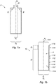
- the figure 1a illustrates a flask F of the prior art.
- this bottle F comprises a body intended to contain a cosmetic product.
- This body extends along a main direction of longitudinal extension X 1 and has a bottom wall at one of its ends, an opening (defined by what may be called a bottle neck) to the opposite end along the main direction and a side wall between said two ends.
- the body further comprises shoulders E, that is to say a narrowing of the dimensions of the body at its upper part, so as to allow the creation of a neck G on which will be fixed a hood (not shown ) by means of opening and closing means part on the neck G and secondly on the hood.
- the body of the bottle F of the prior art is provided in its upper part with a shoulder E thus making it possible to reduce the dimensions d 1 'of the opening of the bottle F with respect to the dimensions D 1 ' of the body to thereby create said neck G (d 1 ' ⁇ D 1 ').
- the invention relates to an applicator assembly 100 for cosmetic product P, adapted to occupy two positions, an open position and a closed position.
- open position is meant the position taken by the applicator assembly, when a cover 90 is detached from a body 112 of a bottle without a neck 110.
- closing position is meant the position taken by the applicator assembly when the cap 90 is fixed to the body 112 of the bottle without a neck 110.
- Said applicator assembly 100 comprises on the one hand a bottle without a neck 110.
- the dimension of the circular cross section of the neck 111 will be constant and not shrunken over the entire upper part of the body 112, also called collar zone Z c , of the bottle without a neck 110.
- the bottle according to the invention will, advantageously, without neck.
- said bottle without neck 110 comprises a body 112 intended generally to contain a cosmetic product P.
- the body 112 of the bottle without neck 110 extends along a main direction of longitudinal extension, said main direction and marked X 3 on the Figures 1b to 9b (The X axis 2 coincides with the axis X 3 in the mounted position of the wiper in the body of the bottle).
- the body 112 has a bottom wall at a first end, said distal end 113, an opening (defined by the neck 111 of the vial 110) at a second opposite end along the main direction, said proximal end 114, and a side wall 115 located between the distal end 113 and the proximal end 114, said side wall 115 having a surface external 116 and an inner surface 117.
- the body 112 is advantageously a rigid piece.
- the term " rigid" which is neither deformable under atmospheric pressure, nor under a force exerted by the fingers of a user.
- Its cross section can be of any shape, in particular polygonal or circular. Preferably, its cross section is circular.
- the body 112 is, for example, based on plastic material, in particular polypropylene. It is produced, in particular by injection or injection blow molding. It can be decorated, in particular by metallization or other.
- Two general zones can be defined on the body 112 of the bottle without neck 110: a neck zone Z c or upper part of the body or head, located closer to the proximal end of the body of the bottle and a bottom zone Z f or lower part of the body or trunk, located closer to the distal end of the body of the bottle.
- the neck zone Z c generally comprises opening and closing means 118 intended to cooperate with complementary means on a hood so as to open and close the bottle without a neck 110, as illustrated on FIG. figure 1 b.
- the opening and closing means 119 on the body 112 of the bottle without neck 110 may be located on the bottom zone Z f of said bottle or in other words, at a distance from the neck zone Z c .
- the neck zone Z c and the bottom zone Z f can come from one and the same piece of plastic material (see Fig. 2b, 3b, 4b , 5b and 6b ).
- the neck zone Z c and the bottom zone Z f may be formed by separate pieces and then assembled together by welding or by clipping with insertion of a seal between the two pieces (see FIG. Fig. 7b, 8b and 9b ).
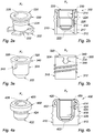
- the applicator assembly 100 also includes a wiper 120 (here shown by the wiper of the embodiment of Fig. 2a and 2b ) having a wiping orifice 122, said wiper 120 being intended to scrape the product cosmetic P excess on an applicator 80, via the wiper orifice 122, when the bottle passes from the closed position to the open position.
- the applicator assembly 100 comprises a wiper 120 attached to the proximal end 114 of the body 112 and extending inwardly of the reservoir.
- the applicator 80 slides through the wiper 120.
- the wiper via its wiper orifice 122, scrapes the cosmetic product P in excess on the applicator, c that is to say on a rod 82 and on an applicator tip 84 fixed on the latter.
- the wiper 120 thus makes it possible to adjust the amount of product present on the applicator tip 84 and avoids excessive application of cosmetic product P to the application surface.
- Said wiper 120 has an outer surface 124 and an inner surface 126.
- the inner surface of the wiper 120 is designed to be in direct contact with the applicator when the vial passes from the open position. at the closed position, or vice versa.
- the outer 124 and inner surfaces 126 are two faces of the same piece, which has a single thickness, that of the material that forms the wiper.
- the wiper 120 is a simple mechanical part, obtained in a single thickness of material.
- the wiper is " flexible ".
- flexible is meant that the wiper is rather malleable and may eventually bend and deform easily, either before insertion into the neck Z c area of the bottle, or at the time of insertion or at the time the passage of the applicator.
- the " rigid " wiper will be inserted into force in the neck Z c area of the bottle so as not to be deformed thereafter. Therefore, the " rigid " wiper, by its nature, will benefit less from the advantages of the present invention.
- the applicator assembly 100 also comprises assembly means comprising at least one positioning means and at least one holding means in position of said wiper 120 with the bottle 110, said connecting means being intended to cooperate with each other. at the proximal end 114 of the vial 110, to block a withdrawal movement of the wiper 120 during the passage of the applicator 80 in the vial 110.
- the assembly means in particular the positioning means (s) and the position holding means (s) of said wiper 120, are integral parts of the wiper 120.
- said means assembly are integrated into the structure of the wiper itself and are only one piece with said wiper.
- the assembly means are made of material with the wiper.
- said assembly means are not additional and separate parts of the wiper to be reported and / or glued to ensure the positioning and / or holding in position of the wiper in the bottle 110 without neck.
- the wiper comprises the assembly means.
- the assembly means being directly integrated with the wiper, this reduces the number of parts and the production cost of the applicator assembly.
- the positioning means and the holding means in position of the wiper may be distinct from each other.
- the positioning means is a flange 230 at the top of the wiper 220 intended to cooperate with the proximal end 214 of the bottle and wherein the position holding means is in the form of at least two fins 232 which protrude at the wiper orifice 222, the two fins 232 being intended to be folded between the outer surface 224 of the wiper and the inner surface 217 of the bottle to ensure the position in position wiper 220 in the bottle 210.
- the number of fins 232 may vary. This number can be between two and eight. More preferably, this number is five, as illustrated in FIG. figure 2a .
- the fins 232 extend radially relative to the main axis.
- the diameter formed by the fins 232 at rest is greater than that of the collar 230 of the wiper 220.
- the positioning means is a collar 340 at the top of the wiper 320 intended to cooperate with the proximal end 314 of the bottle and wherein the holding means in position has at least one technical form 342 protruding from the outer surface 324 of the wiper 320, this technical form 342 being complementary to at least one lumen 344 located on the top of the proximal end 314 of the body 312 of the vial 310.
- Technical form 342 is a bead of material. At the time of insertion of the wiper 320 into the bottle 310, the bead of material will be clipped forcefully into the lumen 344 located at the proximal end 314 of the body 312 of the bottle 310 so that wiper 320 is held in place and can not emerge from said light 344.
- the flange of the first and second embodiments has a circular shape.
- the positioning means and the means for holding the wiper in position may also be merged.
- the positioning means and the position holding means are a single piece.
- the same piece will be used both as a means of positioning and as a means of maintaining position.
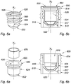
- the positioning means and the position holding means are in the form of a fin 450 which on the one hand rests in the upper part of the wiper 420 and on the other hand comprises a curved end 452, said curved end 452 being intended to cooperate with a complementary portion 454 provided at the outer surface 416 of the side wall of the body 412 of the vial 410.
- the curved end 452 is advantageously flexible so as to match the complementary portion 454 or groove provided at the outer surface 416 of the side wall of the body 412 of the vial 410.
- the assembly means is a thread / tapping assembly 560 so as to allow screwing of the wiper 520 at the proximal end 514 of the vial 510.
- the thread 562 is located on the outer surface 524 of the wiper 520 and is intended to cooperate with the tapping 564 located on the inner surface 517 of the side wall of the body of the vial 510.
- the holding means in the position is in the form of an intermediate piece 670 for pressing and trapping the wiper 620 against the inner surface 617 of the side wall of the body 612 of the vial 610.
- the wiper 620 is first positioned at the proximal end 614 of the body 612 of the vial 610 or in other words at the neck area Zc.
- a flange 630 makes it possible to seat the wiper 620 at the proximal end 614 of the body 612 of the vial 610. Once the wiper 620 has been put in place, it is held in position by being wedged against the surface. internal 617 of the bottle 610 with an intermediate part 670, the intermediate part being in contact with the inner surface 626 of the wiper 620.
- the intermediate piece 670 can be formed from any type of material having a rigidity such that it can trap the wiper 620 against the inner surface 617 of the vial 610. This material must also be compatible with the cosmetic product P, since at the time of the passage of the applicator 80 this material will be in contact with the cosmetic product P.
- the intermediate part 670 can be made of plastic such as polyoxymethylene (POM) or polypropylene (PP).
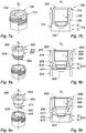
- the present invention can also be adapted to flasks whose body is configured in two parts. As illustrated on Figures 7b, 8b and 9b the body 712, 812, 912 of the vial 710, 810, 910 is in two parts; the two parts, a head Z c and a trunk Z f , are separate pieces.
- the two parts When the body of the bottle is in two parts, the two parts, a head and a trunk, can be obtained from different materials. Bi-injection can be used for the manufacture of vials with this type of two-part configuration.
- the two parts are assembled together by welding or by clipping.
- a seal (not shown) is present between the two parts, that is to say between the head Z c and the trunk Z f .
- the wiper 720, 820, 920 is located at the head Z c of the bottle.
- Figures 7a and 7b illustrate an applicator assembly 700 where the wiper 720 will be positioned and held in position at the head Z c of the vial 710 because it is obtained by overmolding or by bi-injection. Once overmoulding or bi-injection of the wiper 720 and the head Z c of the bottle made, the head Z c will be assembled on the trunk Z f of the bottle 710 by welding or clipping as described above.
- FIG. 8a and 8b illustrate, for their part, an applicator assembly 800 whose positioning means is a flange 873 in the upper part of the wiper 820 intended to cooperate with the proximal end 814 of the bottle and in which the holding means is provided in FIG. less a circular groove 874 dug in the outer surface 824 of the wiper 820, this groove 874 receiving a complementary circular godron 875 located on the inner surface 817 of the side wall 815 of the head Z c of the body 812 of the bottle, for thus ensuring that the wiper 820 is held in position in the bottle 810.
- the Figures 9a and 9b illustrate, an applicator assembly 900 whose positioning means is the collaboration of at least one longitudinal groove 976 and at least one technical form 977.
- the longitudinal groove 976 extends along the main direction X 3 on the inner surface 917 of the sidewall 915 of the head Z c of the body of the vial 910, while the technical form 977 protrudes from the outer surface 924 of the wiper 920.
- the groove 976 is adapted to cooperate with the technical form 977 for positioning the wiper 920 on the bottle.
- the means of maintenance position meanwhile, is at the end of the race of the technical form 977 in the groove 976. Indeed, at the end of said race, the wiper is manipulated to perform a rotation.
- Said wiper in particular rubber, is also configured to cooperate with the cover 90 to ensure a tight closure of the vial 110 in the closed position. More particularly, the tightness of the bottle is ensured by compression of the wiper between the proximal end 114 of the body 112 and the cap 90 in the closed position of the bottle 110.
- the invention also relates to an applicator assembly 100 of a cosmetic product P further comprising an applicator 80, and a cap 90, intended to hold the applicator 80 of cosmetic product inside the body 112 when the bottle 110 is in closing position (Fig. 10).
- the cap 90 may be manipulated by a user and is intended to maintain a cosmetic product applicator 80 inside the body 112, when the bottle 110 is in the closed position.
- the cover 90 is advantageously rigid. It has an inner surface 92, an outer surface 94 and a solid portion 96 in its interior. Its cross section can be of any shape, in particular polygonal or circular. Preferably, its cross section is circular.
- the cover 90 is, for example, based on plastic, in particular polypropylene. It is produced, in particular by injection or injection blow molding. It can be decorated, in particular by metallization or other.
- the bottle 110 further comprises opening and closing means 98, 118 located on the cover 90 on the one hand and on the body 112 of the bottle 110 on the other hand, the opening and closing means 98, 118 being configured so as to cooperate together so as to maintain the closed position of the vial 110.
- the opening and closing means 98, 118 are located on the inner surface 92 of the cap 90 on the one hand and on the side wall 115 of the body 112 of the vial 110 on the other hand. Even more particularly, the opening and closing means 118 are located on the outer surface 116 of the side wall 115 of the body 112 of the bottle 110.
- the opening and closing means 98, 118 comprise a screwing system, the screwing system comprising a threaded portion located on the inner surface 92 of the cover 90 and a threaded portion located on the outer surface 116 of the side wall 115 of the body 112 of the bottle 110.
- the opening and closing means 98, 118 comprise a bayonet system (not shown).
- Said cover 90 may in particular have a gadroon on its inner surface 92, which will be inserted in a cam path (with or without rotation) located on the outer surface 116 of the side wall 115 of the body 112 of the bottle 110.
- the godron and the cam path can be reversed, that is to say the godron will be found on the outer surface 116 of the side wall 115 of the body 112 of the bottle 110 and the cam path will be found on the surface internal 92 of the hood 90.
- the opening and closing means 98, 118 comprise a clipping system (not shown), that is to say latching.
- Said cover 90 may in particular have for this purpose an annular groove on its inner surface 92 in which will be inserted a ring located on the outer surface 116 of the side wall 115 of the body 112 of the bottle 110.
- it may be teeth and / or notches.
- the seal will also be ensured, on the one hand, by the cooperation of the closing means 118 positioned at the body 112 of the bottle with the complementary means located at the cap 90 of the bottle and of on the other hand, when the cover 90 has been fixed on the body 112 of the bottle via the aforementioned closing means, by the cooperation of the cover 90 and the wiper 120.
- the applicator 80 generally comprises an axial rod 82 on the one hand and an applicator tip 84 on the other hand.
- the axial rod 82 extends in a main direction of longitudinal extension, in this case the main direction X 3 and comprises two opposite ends.
- the axial rod 82 is designed to secure the applicator to the cover 90.
- the axial rod 82 is designed to be fixed to the applicator tip 84 As the applicator is generally secured to the cover 90, it forms with the latter a means for gripping said applicator.
- the cover 90 When the cover 90 is fixed on the body 112 of the bottle 110, that is to say when the bottle 110 is in the closed position, the axial rod 82 and the applicator tip 84 extend inside the body 112 of the bottle 110. The applicator is thus immersed in the cosmetic product P contained in the reservoir.
- the user detaches the cover 90 from the body 112 and extracts the applicator from the reservoir. This is called the opening position of the bottle.
- the rod 82 is advantageously rigid. It may be slightly deformed, especially curved, under the effect of efforts applied during makeup, this because of its elongated shape. Said rod 82 is, for example, based on plastic, in particular polypropylene.
- said applicator tip 84 may be a mascara brush, a brush for applying the eyeliner, a lip balm spatula or the like.
- the invention can also be used for any other type of cosmetic products, including lip balm.
- the materials used for the applicator tip 60 may be chosen from the group comprising vegetable fibers (for example: cotton, rayon, cellulose), fibers made of thermoplastic material (for example: polyamide, polyester, nylon), fibers made of material thermoplastic elastically deformable (for example: elastomers, thermoplastic elastomers, vulcanized elastomers), a "sintered” and a foam (for example: polyurethane, polyethylene, polyvinyl chloride, polyether, NBR (natural rubber), SBR (synthetic rubber)).
- a foam for example: polyurethane, polyethylene, polyvinyl chloride, polyether, NBR (natural rubber), SBR (synthetic rubber)
- sintered is meant a product obtained by consolidation by the action of heat of a granular agglomerate more or less compact, with or without fusion of one or more of its constituents.
- any type of applicator tip 84 forming a mascara brush may be used here, whether it is molded
Landscapes
- Closures For Containers (AREA)
- Containers And Packaging Bodies Having A Special Means To Remove Contents (AREA)
Applications Claiming Priority (1)
| Application Number | Priority Date | Filing Date | Title |
|---|---|---|---|
| FR1656055A FR3053220A1 (fr) | 2016-06-29 | 2016-06-29 | Ensemble applicateur pour produit cosmetique |
Publications (2)
| Publication Number | Publication Date |
|---|---|
| EP3295825A2 true EP3295825A2 (de) | 2018-03-21 |
| EP3295825A3 EP3295825A3 (de) | 2018-06-27 |
Family
ID=56855689
Family Applications (1)
| Application Number | Title | Priority Date | Filing Date |
|---|---|---|---|
| EP17176957.3A Withdrawn EP3295825A3 (de) | 2016-06-29 | 2017-06-20 | Applikatoreinheit für kosmetikprodukt |
Country Status (5)
| Country | Link |
|---|---|
| US (1) | US20180000227A1 (de) |
| EP (1) | EP3295825A3 (de) |
| CN (1) | CN107536237A (de) |
| BR (1) | BR102017013995A2 (de) |
| FR (1) | FR3053220A1 (de) |
Cited By (1)
| Publication number | Priority date | Publication date | Assignee | Title |
|---|---|---|---|---|
| FR3100115A1 (fr) | 2019-09-02 | 2021-03-05 | Ets BULLIER SAS | Dispositif de pinceau pour tous secteurs beaux-arts/cosmétique et loisirs créatifs, doté d’un manche rigide recevant un réservoir, ledit pinceau étant apte à distribuer à débit régulier des fluides à comportement non newtonien de type Bingham |
Families Citing this family (2)
| Publication number | Priority date | Publication date | Assignee | Title |
|---|---|---|---|---|
| EP4556393A3 (de) * | 2020-06-02 | 2025-07-02 | Seidel GmbH & Co. KG | Verschlusskappenanordnung |
| IT202000019549A1 (it) * | 2020-08-06 | 2022-02-06 | Tanklux Srl | Contenitore per prodotti cosmetici in genere, in particolare i prodotti cosmetici per gli occhi e per le labbra |
Citations (1)
| Publication number | Priority date | Publication date | Assignee | Title |
|---|---|---|---|---|
| US4332494A (en) | 1977-12-05 | 1982-06-01 | Plough, Inc. | Adjustable cosmetic wiper |
Family Cites Families (7)
| Publication number | Priority date | Publication date | Assignee | Title |
|---|---|---|---|---|
| US4627454A (en) * | 1974-01-08 | 1986-12-09 | Dahm Klaus Peter | Cosmetic stick with applicator |
| US5397193A (en) * | 1993-08-31 | 1995-03-14 | L'oreal S.A. | Applicator wiper |
| FR2745272B1 (fr) * | 1996-02-28 | 1998-04-24 | Oreal | Dispositif de conditionnement et d'application et element de recharge pour un tel dispositif |
| FR2771907B1 (fr) * | 1997-12-10 | 2000-02-18 | Oreal | Ensemble de conditionnement et d'application d'un produit, notamment cosmetique |
| FR2793218B1 (fr) * | 1999-05-07 | 2001-07-13 | Oreal | Dispositif de conditionnement et d'application d'un produit, notamment un produit cosmetique |
| FR2836031B1 (fr) * | 2002-02-19 | 2004-11-26 | Oreal | Applicateur comportant un element d'application configure pour appliquer un produit sur la peau |
| FR2933961B1 (fr) * | 2008-07-16 | 2013-06-21 | Valois Sas | Dispositif applicateur de produit fluide. |
-
2016
- 2016-06-29 FR FR1656055A patent/FR3053220A1/fr not_active Withdrawn
-
2017
- 2017-06-20 EP EP17176957.3A patent/EP3295825A3/de not_active Withdrawn
- 2017-06-28 CN CN201710508357.4A patent/CN107536237A/zh active Pending
- 2017-06-28 BR BR102017013995-6A patent/BR102017013995A2/pt not_active Application Discontinuation
- 2017-06-29 US US15/638,288 patent/US20180000227A1/en not_active Abandoned
Patent Citations (1)
| Publication number | Priority date | Publication date | Assignee | Title |
|---|---|---|---|---|
| US4332494A (en) | 1977-12-05 | 1982-06-01 | Plough, Inc. | Adjustable cosmetic wiper |
Cited By (1)
| Publication number | Priority date | Publication date | Assignee | Title |
|---|---|---|---|---|
| FR3100115A1 (fr) | 2019-09-02 | 2021-03-05 | Ets BULLIER SAS | Dispositif de pinceau pour tous secteurs beaux-arts/cosmétique et loisirs créatifs, doté d’un manche rigide recevant un réservoir, ledit pinceau étant apte à distribuer à débit régulier des fluides à comportement non newtonien de type Bingham |
Also Published As
| Publication number | Publication date |
|---|---|
| FR3053220A1 (fr) | 2018-01-05 |
| BR102017013995A2 (pt) | 2018-01-16 |
| EP3295825A3 (de) | 2018-06-27 |
| US20180000227A1 (en) | 2018-01-04 |
| CN107536237A (zh) | 2018-01-05 |
Similar Documents
| Publication | Publication Date | Title |
|---|---|---|
| CA2389875C (fr) | Essoreur a montage simplifie | |
| FR2968517A1 (fr) | Dispositif de conditionnement d'un produit cosmetique | |
| FR2968516A1 (fr) | Dispositif de conditionnement d'un produit cosmetique | |
| EP2974618B1 (de) | Abstreifer für einen kosmetikbehälter, behälter mit solch einem abstreifer und applikatoranordung mit solch einem behälter | |
| EP1050231A1 (de) | Vorrichtung zum Aufbewahren und Auftragen von kosmetischen Produkten | |
| WO2010106235A1 (fr) | Ensemble comprenant un systeme de conditionnement d'un produit a fermeture etanche. | |
| FR2798649A1 (fr) | Dispositif pour le conditionnement separe de deux composants , leur melange et la distribution du melange ainsi obtenu | |
| EP3248500B1 (de) | Flasche für ein kosmetisches produkt und applikatoranordnung mit einer flasche dieser art und einem applikator für das kosmetische produkt | |
| EP3295825A2 (de) | Applikatoreinheit für kosmetikprodukt | |
| FR3005835A1 (fr) | Dispositif d'essuyage pour produit pateux, procede de montage associe | |
| FR3016274A1 (fr) | Dispositif d'essorage avec levre d'essuyage a geometrie variable | |
| EP3166862B1 (de) | Wimperntusche-applikator, behälter, herstellungsverfahren und vorrichtung | |
| EP3285611B1 (de) | Behälter, insbesondere ein fläschchen zur aufnahme eines kosmetischen produktes | |
| EP1614367B1 (de) | Vorrichtung zum Aufbewahren und zum Auftragen eines Produktes | |
| FR2978738A1 (fr) | Dispositif de conditionnement muni d'un moyen d'etancheite | |
| EP3765206A1 (de) | Behälter für fluidpprodukt | |
| EP1444917B1 (de) | Vorrichtung zum Aufbewahren und Auftragen eines Produktes | |
| FR3142871A1 (fr) | Organe d’application de produit cosmétique, ensemble de conditionnement d’un produit cosmétique et procédé d’assemblage d’un organe d’application de produit cosmétique | |
| EP1690466A1 (de) | Vorrichtung zum Aufbewahren und Auftragen | |
| EP3731695B1 (de) | Wischvorrichtung für einen applikator für ein kosmetisches produkt | |
| EP1384415B1 (de) | Behälter mit einem Hals der zwei Teile mit verschiedenen Durchmessern aufweist | |
| FR3051642A1 (fr) | Applicateur de produit cosmetique articule et ensemble de conditionnement et d'application associe | |
| EP1347696B1 (de) | Versiegelte packung für kosmetikprodukt | |
| FR3068222A1 (fr) | Embout applicateur pour produit cosmetique, applicateur et ensemble applicateur associes | |
| FR2900803A1 (fr) | Article d'aide a l'application d'un produit cosmetique, notamment d'un vernis a ongles. |
Legal Events
| Date | Code | Title | Description |
|---|---|---|---|
| PUAI | Public reference made under article 153(3) epc to a published international application that has entered the european phase |
Free format text: ORIGINAL CODE: 0009012 |
|
| STAA | Information on the status of an ep patent application or granted ep patent |
Free format text: STATUS: THE APPLICATION HAS BEEN PUBLISHED |
|
| AK | Designated contracting states |
Kind code of ref document: A2 Designated state(s): AL AT BE BG CH CY CZ DE DK EE ES FI FR GB GR HR HU IE IS IT LI LT LU LV MC MK MT NL NO PL PT RO RS SE SI SK SM TR |
|
| AX | Request for extension of the european patent |
Extension state: BA ME |
|
| PUAL | Search report despatched |
Free format text: ORIGINAL CODE: 0009013 |
|
| TPAC | Observations by third parties |
Free format text: ORIGINAL CODE: EPIDOSNTIPA |
|
| AK | Designated contracting states |
Kind code of ref document: A3 Designated state(s): AL AT BE BG CH CY CZ DE DK EE ES FI FR GB GR HR HU IE IS IT LI LT LU LV MC MK MT NL NO PL PT RO RS SE SI SK SM TR |
|
| AX | Request for extension of the european patent |
Extension state: BA ME |
|
| RIC1 | Information provided on ipc code assigned before grant |
Ipc: A45D 40/26 20060101AFI20180524BHEP Ipc: A45D 34/04 20060101ALI20180524BHEP |
|
| STAA | Information on the status of an ep patent application or granted ep patent |
Free format text: STATUS: REQUEST FOR EXAMINATION WAS MADE |
|
| TPAC | Observations by third parties |
Free format text: ORIGINAL CODE: EPIDOSNTIPA |
|
| 17P | Request for examination filed |
Effective date: 20181206 |
|
| RBV | Designated contracting states (corrected) |
Designated state(s): AL AT BE BG CH CY CZ DE DK EE ES FI FR GB GR HR HU IE IS IT LI LT LU LV MC MK MT NL NO PL PT RO RS SE SI SK SM TR |
|
| STAA | Information on the status of an ep patent application or granted ep patent |
Free format text: STATUS: EXAMINATION IS IN PROGRESS |
|
| 17Q | First examination report despatched |
Effective date: 20190911 |
|
| STAA | Information on the status of an ep patent application or granted ep patent |
Free format text: STATUS: THE APPLICATION IS DEEMED TO BE WITHDRAWN |
|
| 18D | Application deemed to be withdrawn |
Effective date: 20200603 |