EP3295848A1 - Modul für die herstellung einer umlaufenden mauerhalterung für eine badewanne vom typ nicht selbsttragend, und kit aus mindestens vier modulen - Google Patents
Modul für die herstellung einer umlaufenden mauerhalterung für eine badewanne vom typ nicht selbsttragend, und kit aus mindestens vier modulen Download PDFInfo
- Publication number
- EP3295848A1 EP3295848A1 EP17191431.0A EP17191431A EP3295848A1 EP 3295848 A1 EP3295848 A1 EP 3295848A1 EP 17191431 A EP17191431 A EP 17191431A EP 3295848 A1 EP3295848 A1 EP 3295848A1
- Authority
- EP
- European Patent Office
- Prior art keywords
- module
- wall
- segments
- modules
- bath
- Prior art date
- Legal status (The legal status is an assumption and is not a legal conclusion. Google has not performed a legal analysis and makes no representation as to the accuracy of the status listed.)
- Withdrawn
Links
Images


Classifications
-
- A—HUMAN NECESSITIES
- A47—FURNITURE; DOMESTIC ARTICLES OR APPLIANCES; COFFEE MILLS; SPICE MILLS; SUCTION CLEANERS IN GENERAL
- A47K—SANITARY EQUIPMENT; ACCESSORIES THEREFOR, e.g. TOILET ACCESSORIES
- A47K3/00—Baths; Showers; Appurtenances therefor
- A47K3/16—Devices for fastening baths to floors or walls; Adjustable bath feet ; Lining panels or attachments therefor
-
- E—FIXED CONSTRUCTIONS
- E04—BUILDING
- E04C—STRUCTURAL ELEMENTS; BUILDING MATERIALS
- E04C3/00—Structural elongated elements designed for load-supporting
- E04C3/005—Girders or columns that are rollable, collapsible or otherwise adjustable in length or height
Definitions
- the invention relates to a module for the manufacture of a wall peripheral support for a non-self-supporting type bathtub, such as an acrylic bath or other synthetic materials.
- the invention also relates to a kit for manufacturing the peripheral support. This kit includes at least four modules.
- Baths of the non-self-supporting type are mostly used today because of their lightness. However, they have the disadvantage of having a low flexural strength. Thus, unlike cast iron tubs, the peripheral edge of acrylic or resin tubs must be supported over most of its periphery to avoid creating deformations when the user climbs into his bathtub. In addition, the bathtub is raised above the ground and rests on support feet.
- the bathtub is installed against a bathroom wall, often against two walls forming a right angle. Corner brackets are then fixed against the walls of the bathroom to support at least a portion of the peripheral edge of the bath.
- installers use metal angles or wooden cleats as a support. The installer must then adjust the length of the support and drill the holes for the passage of the fixing screws to the bathroom wall, which makes the installation relatively long.
- the use of wood in an area that may be exposed to water infiltration is not recommended.
- each module comprises several segments. Folding lines are provided between each segment. These fold lines are formed by slots and / or notches.
- a disadvantage of this module is that the segments are not intended to be detached from each other, for example by hand. So we can not easily adjust the length of the module.
- two modules can not be assembled together to form a continuous wall mount.
- the invention more particularly intends to remedy, by proposing a means for manufacturing and installing a peripheral wall-mounted bathtub support more quickly and more easily.
- the invention relates to a module for the manufacture of a wall-mounted peripheral support for a bathtub of the non-self-supporting type, this module being designed to be fixed against a bathroom wall and comprising at least two breakable segments.
- each longitudinal end of the module comprises assembly means with another identical module.
- the invention aims to provide a wall-mounted modular bathtub support device, which is assembled on site from modules.
- the length of each module can be adjusted by removing one or more segments of the module.
- the number of modules used to make the support is chosen according to the dimensions of the bathtub.
- the length of the support can therefore be adjusted as close as possible to the dimensions of the bath. Thanks to the invention, the installer does not have to cut manually, for example using a saw, a wooden battens or an angle to adjust its length. This saves time during installation.
- the invention also relates to a kit for manufacturing a tub wall peripheral support, comprising at least four modules as described above.
- a bathtub of the non-self-supporting type such as an acrylic bath or any other synthetic material, has the advantage of having a very low mass in comparison with cast iron baths for example.
- the disadvantage is its low flexural strength, which makes it necessary to fix a support to the wall to support the rim of the tub and thus to prevent the bathtub from deforming when a user goes up inside.
- the wall support S is intended to be fixed against a wall 3 of bathroom and to support at least a portion of a peripheral edge 10 of the bath 1, so it is referred to a wall peripheral support.
- the edge 10 is an edge bent at 90 ° downwards.
- the wall-mounted peripheral support S is modular: it is manufactured from several modules 2 assembled with each other. All these modules are grouped in a kit (not shown), which comprises at least four modules 2. Only one module 2 of this kit is described below in relation to the Figures 2 to 4 , the other modules of the kit being identical.
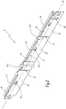
- the figure 2 represents the visible side of the module 2 when the latter is fixed against the wall 3 of the bathroom.
- the module 2 extends in a longitudinal direction X2 which is substantially horizontal when the module 2 is fixed to the wall.
- the longitudinal direction X2 represents the largest dimension of the module.
- the module 2 is shown partially in length on the Figures 2 to 4 .
- the module 2 comprises at least two breakable segments 20, in particular six breakable segments 20, separated by slots 22.
- Each slot 22 is an opening extending in a direction perpendicular to the longitudinal axis X2 of the module 2, that is to say in a vertical direction in fixed configuration of the module 2.
- Each slot 22 forms a break line of the module, corresponding to a line of weakness at break of the module. This is a line in which the module is cut when the two segments 20 located on either side of the slot 22 are folded towards each other.
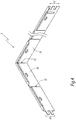
- module 2 is foldable. More specifically, the segments 20 of the module 2 can be folded towards each other, at the slots 22, to form a right angle.
- the slots 22 thus also form fold lines of the module 2.
- the slots 22 are configured so that the module 2 can be bent at 90 ° without breaking.
- the module 2 can thus be installed on two bathroom walls forming a right angle, that is to say at the corner of a room.
- the break between two segments 20 is obtained after repeated bending or by means of a cutting plier.
- the slots 22 are configured so that the segments 20 can not be folded without breaking. Module 2 is not foldable.
- Each segment 20 has a length, measured parallel to the axis X2, which is equal to 10 cm.
- the length of the module 2 is therefore in the example of the order of 60 cm.
- a kit comprising four modules thus makes it possible to form a wall support with a length of up to 240 cm.
- the kit may comprise more than four modules.
- the fact that the module 2 consists of breakable segments makes it possible to better adjust the length of the module according to its location. Take the example of a bathtub 160 cm long and 70 cm wide installed against two perpendicular walls. The length of the edge of the tub to support is therefore a total of 230 cm.
- the wall peripheral support is then made from four modules, namely three 60 cm modules (six segments) and one 50 cm module (five segments).
- a 60 cm module is used to make the angle of the wall.
- This module is bent at 90 ° and includes five segments that support part of the long side of the tub and a segment that supports part of a small side of the tub.
- This modularity prevents the installer from manually cutting, for example with the saw, a wooden angle to adjust the length.
- each segment 20 defines a passage opening 28 for a fixing screw (not shown) to the bathroom wall 3. This saves time during installation because the holes are already drilled in modules 2.
- Each segment 20 comprises a rim 24 for receiving the edge 10 of the bath.
- the flange 24 is flat and horizontal when the module 2 is fixed to the wall.
- a recess 26 is formed at the free end of the rim 24. This recess 26 is bent upwards when the module 2 is fixed to the wall. It allows to retain the edge 10 of the bath as the bath 1 is not completely immobilized. This prevents the edge 10 of the bath 1 can fall out of the peripheral support S, for example due to mishandling.
- a silicone support seal (not shown) is applied to the flange 24 for contact with the edge 10 of the bath.
- Each flange 24 comprises a large side 24.1, which extends parallel to the axis X2 and which forms the recess 26, and two small sides 24.2.
- one or each of the small sides 24.2 of each flange 24 extends obliquely with respect to the long side 24.1. More precisely, the two short sides 24.2 converge towards the long side 24.1.
- only one of the narrow sides 24.2 of the flange 24 may be angled, in particular that disposed on the side of the other segments 20 of the module.
- the module 2 delimits an oblong slot 30, which extends parallel to the slots 22.
- the light 30 is in the example delimited by an end segment of the module 2. This light 30 makes it possible to hang the modules 2 on standard media in sales outlets.
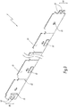
- the figure 3 represents the side of the module intended to be positioned against the wall 3 of the bathroom.
- the module 2 comprises, on this side, at least one double-sided adhesive strip 32 for temporarily immobilizing the module 2 against the wall 3 before tightening the screws.
- the module 2 comprises two double-sided adhesive strips 34, respectively disposed on the rear face of the second and fifth segments 20.
- each longitudinal end of the module 2 comprises assembly means with another identical module 2 '.
- the assembly means are of the tenon-mortise type.
- a first longitudinal end 40 of the module 2 comprises at least one pin 42, in particular two pins 42
- the second longitudinal end 50 of the module 2 comprises at least one corresponding mortise 52, in particular two mortises correspondingly 52.
- several modules 2 can be put end to end, as shown in FIG. figure 5 .
- the assembly means 42 and 52 have the advantage that when two modules are put end to end and assembled, then they are perfectly aligned in the longitudinal direction.
- Each module 2 of the support S is made from a sheet which is cut, pierced and folded to form the flanges 24 and the recesses 26.
- the number of breakable segments 20 may be different from 6, for example equal to 2, 3 or 4.
- At least one slot 22, or each slot 22, is replaced by a section narrowing, that is to say a portion of reduced thickness relative to the remainder of the module. This part extends over all or part of the height of the module, that is to say in a direction perpendicular to the axis X2.
- At least one slot 22, or each slot 22, is replaced by a plurality of disjointed slots aligned with each other.
Landscapes
- Engineering & Computer Science (AREA)
- Architecture (AREA)
- Health & Medical Sciences (AREA)
- Public Health (AREA)
- Civil Engineering (AREA)
- Structural Engineering (AREA)
- Epidemiology (AREA)
- General Health & Medical Sciences (AREA)
- Residential Or Office Buildings (AREA)
Applications Claiming Priority (1)
| Application Number | Priority Date | Filing Date | Title |
|---|---|---|---|
| FR1658692A FR3056092B1 (fr) | 2016-09-16 | 2016-09-16 | Module pour la fabrication d'un support peripherique mural pour une baignoire du type non autoportant et kit comprenant au moins quatre modules |
Publications (1)
| Publication Number | Publication Date |
|---|---|
| EP3295848A1 true EP3295848A1 (de) | 2018-03-21 |
Family
ID=57348960
Family Applications (1)
| Application Number | Title | Priority Date | Filing Date |
|---|---|---|---|
| EP17191431.0A Withdrawn EP3295848A1 (de) | 2016-09-16 | 2017-09-15 | Modul für die herstellung einer umlaufenden mauerhalterung für eine badewanne vom typ nicht selbsttragend, und kit aus mindestens vier modulen |
Country Status (2)
| Country | Link |
|---|---|
| EP (1) | EP3295848A1 (de) |
| FR (1) | FR3056092B1 (de) |
Citations (4)
| Publication number | Priority date | Publication date | Assignee | Title |
|---|---|---|---|---|
| US1955485A (en) * | 1931-10-09 | 1934-04-17 | Capra John | Bathtub support |
| US7070667B1 (en) * | 2004-03-19 | 2006-07-04 | Mark E Kirby | Method and tool for installing tile on a wall |
| DE202012011713U1 (de) * | 2012-12-07 | 2013-01-14 | Repabad Gmbh | Montageschiene |
| CA2820165A1 (en) * | 2013-06-17 | 2014-12-17 | John D. Jackman | Adjustable bathtub ledger strap and method of use |
-
2016
- 2016-09-16 FR FR1658692A patent/FR3056092B1/fr active Active
-
2017
- 2017-09-15 EP EP17191431.0A patent/EP3295848A1/de not_active Withdrawn
Patent Citations (4)
| Publication number | Priority date | Publication date | Assignee | Title |
|---|---|---|---|---|
| US1955485A (en) * | 1931-10-09 | 1934-04-17 | Capra John | Bathtub support |
| US7070667B1 (en) * | 2004-03-19 | 2006-07-04 | Mark E Kirby | Method and tool for installing tile on a wall |
| DE202012011713U1 (de) * | 2012-12-07 | 2013-01-14 | Repabad Gmbh | Montageschiene |
| CA2820165A1 (en) * | 2013-06-17 | 2014-12-17 | John D. Jackman | Adjustable bathtub ledger strap and method of use |
Also Published As
| Publication number | Publication date |
|---|---|
| FR3056092B1 (fr) | 2019-06-14 |
| FR3056092A1 (fr) | 2018-03-23 |
Similar Documents
| Publication | Publication Date | Title |
|---|---|---|
| EP1127394B1 (de) | Leitungshalterung auf einem trägerelement mit mindestens einer öffnung und tragender aufbau für kabelführung. | |
| FR3018843B1 (fr) | Cloture, kit et procede pour l'installation de ladite cloture | |
| CH631062A5 (fr) | Dispositif d'exposition mural. | |
| EP2841663A1 (de) | Vorrichtung zur abdeckung einer gebäudestruktur und mit einer solchen vorrichtung abgedeckte struktur | |
| CA2973677A1 (fr) | Dispositif de fixation de panneau solaire | |
| EP0774032A1 (de) | Variabel gestaltete treppe | |
| WO2007088301A1 (fr) | Dispositif de fixation pour pot de fleurs | |
| FR2694953A1 (fr) | Pièce de raccordement pour monter une traverse sur un raidisseur de mur-rideau. | |
| FR3056092B1 (fr) | Module pour la fabrication d'un support peripherique mural pour une baignoire du type non autoportant et kit comprenant au moins quatre modules | |
| FR2766905A1 (fr) | Profile a rainure(s) pour la mise en place d'au moins un accessoire | |
| EP2841664B1 (de) | System zur abdeckung eines metallblechs | |
| EP0010820B1 (de) | Kasten für elektrische Geräte | |
| EP2575182B1 (de) | Befestigungsvorrichtung für mindestens ein Photovoltaikmodul auf einer tragenden Struktur, Solarplatte und Baugruppe, die mindestens zwei Solarplatten umfasst, die jeweils mit einer solchen Vorrichtung ausgestattet sind | |
| EP1365492A1 (de) | Einbaugehäuse für elektrische Bauteile | |
| EP3167769B1 (de) | Universelle befestigungsvorrichtung für ausstellungsmodell eines duschsystems an einer ausstellwand | |
| FR2664633A1 (fr) | Plafond suspendu. | |
| EP2636816A1 (de) | Einheit zur Ummantelung einer Wand | |
| FR2970017A1 (fr) | Dispositif pour l'assemblage d'une marche sur un support | |
| WO2016108025A1 (fr) | Procédé d'isolation, suspente et ensemble associés | |
| FR2764361A1 (fr) | Double bride pour canalisations de surface | |
| WO2015086650A1 (fr) | Dispositif de maintien d'une presse contre un objet | |
| FR2769934A1 (fr) | Support pour gouttiere | |
| FR2815221A1 (fr) | Pot de fleurs a fixation sur plusieurs supports | |
| FR2618495A1 (fr) | Dispositif de fixation ponctuelle de plaques sur une structure support | |
| EP0032649A1 (de) | Vorrichtung zum Stabilisieren und Verteilen des Druckes eines Rahmenteils |
Legal Events
| Date | Code | Title | Description |
|---|---|---|---|
| PUAI | Public reference made under article 153(3) epc to a published international application that has entered the european phase |
Free format text: ORIGINAL CODE: 0009012 |
|
| AK | Designated contracting states |
Kind code of ref document: A1 Designated state(s): AL AT BE BG CH CY CZ DE DK EE ES FI FR GB GR HR HU IE IS IT LI LT LU LV MC MK MT NL NO PL PT RO RS SE SI SK SM TR |
|
| AX | Request for extension of the european patent |
Extension state: BA ME |
|
| 17P | Request for examination filed |
Effective date: 20180821 |
|
| RBV | Designated contracting states (corrected) |
Designated state(s): AL AT BE BG CH CY CZ DE DK EE ES FI FR GB GR HR HU IE IS IT LI LT LU LV MC MK MT NL NO PL PT RO RS SE SI SK SM TR |
|
| GRAP | Despatch of communication of intention to grant a patent |
Free format text: ORIGINAL CODE: EPIDOSNIGR1 |
|
| INTG | Intention to grant announced |
Effective date: 20191014 |
|
| STAA | Information on the status of an ep patent application or granted ep patent |
Free format text: STATUS: THE APPLICATION IS DEEMED TO BE WITHDRAWN |
|
| 18D | Application deemed to be withdrawn |
Effective date: 20200225 |