EP3295907B1 - Protection contre les chocs pour fil électrique implantable - Google Patents
Protection contre les chocs pour fil électrique implantable Download PDFInfo
- Publication number
- EP3295907B1 EP3295907B1 EP17192321.2A EP17192321A EP3295907B1 EP 3295907 B1 EP3295907 B1 EP 3295907B1 EP 17192321 A EP17192321 A EP 17192321A EP 3295907 B1 EP3295907 B1 EP 3295907B1
- Authority
- EP
- European Patent Office
- Prior art keywords
- lead
- radius
- wires
- core
- electric lead
- Prior art date
- Legal status (The legal status is an assumption and is not a legal conclusion. Google has not performed a legal analysis and makes no representation as to the accuracy of the status listed.)
- Active
Links
Images


Classifications
-
- A—HUMAN NECESSITIES
- A61—MEDICAL OR VETERINARY SCIENCE; HYGIENE
- A61N—ELECTROTHERAPY; MAGNETOTHERAPY; RADIATION THERAPY; ULTRASOUND THERAPY
- A61N1/00—Electrotherapy; Circuits therefor
- A61N1/02—Details
- A61N1/04—Electrodes
- A61N1/05—Electrodes for implantation or insertion into the body, e.g. heart electrode
- A61N1/0526—Head electrodes
- A61N1/0541—Cochlear electrodes
Definitions
- the present invention relates to medical implants, and more specifically to an implantable electrode arrangement used in medical implant systems such as middle ear implants (MEI), cochlear implants (CI) and vestibular implants (VI).
- MEI middle ear implants
- CI cochlear implants
- VI vestibular implants
- a normal ear transmits sounds as shown in Figure 1 through the outer ear 101 to the tympanic membrane (eardrum) 102, which moves the bones of the middle ear 103 (malleus, incus, and stapes) that vibrate the oval window and round window openings of the cochlea 104.
- the cochlea 104 is a long narrow duct wound spirally about its axis for approximately two and a half turns. It includes an upper channel known as the scala vestibuli and a lower channel known as the scala tympani, which are connected by the cochlear duct.
- the cochlea 104 forms an upright spiraling cone with a center called the modiolar where the spiral ganglion cells of the acoustic nerve 113 reside.
- the fluid-filled cochlea 104 functions as a transducer to generate electric pulses which are transmitted to the cochlear nerve 113, and ultimately to the brain.
- Hearing is impaired when there are problems in the ability to transduce external sounds into meaningful action potentials along the neural substrate of the cochlea 104.
- auditory prostheses have been developed.
- a conventional hearing aid may be used to provide acoustic-mechanical stimulation to the auditory system in the form of amplified sound.
- a cochlear implant with an implanted electrode contact can electrically stimulate auditory nerve tissue with small currents delivered by multiple electrode contacts distributed along the electrode.
- Figure 1 also shows some components of a typical cochlear implant system which includes an external microphone that provides an audio signal input to an external signal processor 111 where various signal processing schemes can be implemented.
- the processed signal is then converted into a digital data format, such as a sequence of data frames, for transmission into the implant 108.
- the implant 108 also performs additional signal processing such as error correction, pulse formation, etc., and produces a stimulation pattern (based on the extracted audio information) that is sent through an electrode lead 109 to an implanted electrode array 110.
- this electrode array 110 includes multiple stimulation contacts 112 on its surface that provide selective stimulation of the cochlea 104.
- the electrode array 110 contains multiple lead wires embedded in a soft silicone body referred to as the electrode carrier.
- the electrode array 110 needs to be mechanically robust, and yet flexible and of small size to be inserted into the cochlea 104.
- the material of the electrode array 110 needs to be soft and flexible in order to minimize trauma to neural structures of the cochlea 104. But an electrode array 110 that is too floppy tends to buckle too easily so that the electrode array 110 cannot be inserted into the cochlea 104 up to the desired insertion depth.
- U.S. Patent Publication 2010/0305676 (“Dadd”) describes winding the lead wires in the extra-cochlear segment of the electrode lead in a helical shape to make that portion of the electrode lead stronger. Dadd is quite clear that such a helical portion does not extend into the intra-cochlear electrode array which needs to be much more flexible than the extra-cochlear lead in order to minimize trauma to the cochlear tissues when the array is inserted.
- U.S. Patent Publication 2010/0204768 (“Jolly”) describes winding the individual lead wires in the intra-cochlear electrode array in an elongated helical shape where each wire is separate and independent.
- Electrode leads of active implantable medical devices including Middle Ear Implants (MEI's), Cochlear Implants (CI's), Brainstem Implants (BI's) and Vestibular Implants (VI's) need to be small in diameter but also they carry multiple lead wires. Electrode leads also need to be robust against external mechanical impacts, especially in locations where the electrode lead is placed on top of the skull bone only covered by the skin. In case of a mechanical impact on an unprotected electrode lead, the elastic silicone electrode carrier material is compressed and the electrode lead becomes temporarily locally thinner and elongated. Lead wires at the affected location experience local tensile forces and can even break. This is also the case for helically formed wires within a silicone electrode carrier since they are forced to expand nearly the same amount as the carrier material itself.
- Some implant designs arrange for the electrode lead to exits the implantable processor housing so that the electrode lead never lies superficially on top of bone.
- One disadvantage of such designs in the case of cochlear implants is that the implant housing must be placed in a very exactly defined position relative to the ear.
- the surgeon is recommended to drill an electrode channel into the bone, which is time consuming so that not every surgeon follows the recommendations.
- Some electrode lead design include a rigid impact protector that surrounds the electrode lead, but that approach reduces the flexibility of the electrode lead which in turn makes the surgical implantation procedure more difficult. And in case of a mechanical impact in the area of the electrode lead, a rigid impact protector may protect the electrode from damage but also may cause trauma in the surrounding tissue when it is pressed against the protector.
- US2010/0179360 describes an implantable lead for a medical device which includes an electrically conductive conductor coil extending between the proximal and the distal end of the lead body, the conductor coil wound in a first winding direction under tension.
- the lead body also includes a plastic ribbon wound around the conductor coil in a second winding direction opposite to the first winding direction without releasing the tension of the conductor coil.
- US2006/089691 discloses an implantable lead which has a lead body construction designed to accommodate loading forces exerted on the lead boy during patient movement.
- WO2012/154256 describes a method for forming a wire construct which includes forming a groove in a polymer having a mouth that is narrower than a width of a deeper portion of the groove and placing a substantial length of wire in the groove, the wire having a larger cross-sectional dimension that the mouth of the groove.
- the wire construct is to be used for implantable stimulation leads, such as cochlear stimulation lead of a neurostimulation lead.
- the present invention seeks to provide an implantable electric lead arrangement. While the following description uses the specific example of a cochlear implant electrode lead connected at one end to an implantable cochlear implant processor and connected at another end to an intracochlear electrode array, one of skill in the field will understand that the invention is not limited to that particular specific context and is more broadly understood as any sort of implantable electric lead for medical implant systems-such as middle ear implants (MEI), cochlear implants (CI), brainstem implants (BI), and vestibular implants (VI)-that connects different units of such an implant system such as an implantable microphone or other sensor with another device in the system.
- MMI middle ear implants
- CI cochlear implants
- BI brainstem implants
- VI vestibular implants
- the invention therefore provides an implantable electric lead arrangement for a medical implant system as set out in claim 1.
- the electric lead contains parallel lead wires wound in an elongated helix about a central longitudinal axis.
- a lead core is fixed and enclosed within the wire helix for providing impact strain relief to the lead wires by resisting radial and/or axial deformation from external impact force.
- the lead core may be made of a flexible polymer material, which may have an elastic module value and/or a shore-A hardness value greater than some given threshold value. Or the lead core may be made of a flexible metallic material, bundled fibers, or bundled wires.
- the lead core may have a rod shape or a conical shape.
- the lead core may have a diameter less than 0.7 times the diameter of the electric lead.
- the helix shape may have a diameter less than 1.5 times the diameter of the lead core.
- Some embodiments may also have support ribs that are perpendicular to the lead core and distributed along the length of the lead core.
- the electric lead may specifically be a cochlear implant electrode lead connected at one end to an implantable cochlear implant processor and connected at another end to an intracochlear electrode array
- the implantable electric lead arrangement for a medical implant system includes an electric lead that contains parallel lead wires wound in an elongated helix about a central longitudinal axis. At least one support wire is parallel to the lead wires and has a higher strain energy absorption capacity than the lead wires to mechanically strengthen the lead wires against external impact force.
- the at least one support wire and the lead wires of the helix may form a single integrated structural element.
- the at least one support wire and the lead wires may be structurally separate elements wound together in a helical ribbon.
- Figure 2 shows how longitudinal deformation of a cochlear implant electrode lead 109 occurs in response to radial and/or axial deformation caused by an external impact or exerted pressure onto the electrode lead 109 which thins and elongates the resilient material of the lead carrier 201 and creates a local tensile force on the lead wires 202.
- Such longitudinal deformation should be prevented or strongly suppressed.
- Reduced longitudinal deformation as a response to radially induced deformation is especially a challenge in electric leads 109 having helically wound lead wires 202 as in Fig. 2 .
- the examples are directed to an implantable electric lead, for example, a cochlear implant electric lead 109, which is more robust against radial and/or axial deformation to avoid wire breakage within the electric lead 109. This most often occurs relatively close to the stimulator housing where after implantation the electric lead 109 runs on top of the skull bone.
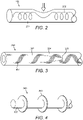
- Figure 3 shows one embodiment where an electric lead 300 which has an lead carrier material 304 that contains parallel embedded lead wires 301.
- the lead wires 301 are wound in an elongated helix about a central longitudinal axis of the electrode lead 300.
- the embedded lead wires 301 may also be arranged in other suitable forms than in an elongated helix.
- the lead wires 301 may be shaped in a substantially sinusoidal form about a central longitudinal axis of the electric lead 300.
- a conical lead core 302 is fixed and enclosed in the lead carrier 304 within the wire helix for providing impact strain relief to the lead wires 301 by resisting radial and/or axial deformation from external impact force.
- the lead core 302 may be made of a flexible polymer material that may have an elastic module value and/or a shore-A hardness value greater than some given threshold value.
- the lead carrier 304 material may be silicone of medium shore-A hardness (e.g. NUSIL MED-4244 or Applied Silicone LSR40), while the lead core 302 material may have a higher shore-A hardness (e.g. NUSIL MED-4770).
- the lead core 302 may be made of a flexible metallic material, for example, a shape memory alloy (SMA) such as Nitinol.
- the flexible metallic material may be a single wire having a thickness e.g. between 0.4 mm and 0.1 mm, or more preferably between 0.3 mm and 0.2 mm.
- the lead core 304 may be formed from bundled fibers or wires which may run in parallel or be braided.
- Lead core fibers may be made of inorganic materials such as carbon basalt (e.g. CBF - continuous basalt fibers) or glass, or from organic materials such as polypropylene, polyethylene, polyamide, aramide, spun liquid crystal polymer (e.g. Vectran) or other materials from these groups.
- they may be made from shape memory alloy such as Nitinol, e.g. having a bundle thickness between 0.4 mm and 0.1 mm, or more preferably between 0.3 mm and 0.2 mm.
- shape memory alloy such as Nitinol, e.g. having a bundle thickness between 0.4 mm and 0.1 mm, or more preferably between 0.3 mm and 0.2 mm.
- the material of the lead core 302 resists elongation of the electric lead 300 in case of a mechanical impact and also restricts diametric compression of the electric lead 300.
- the flexibility of the electric lead 300 should be preserved. It is important that the surgeon can be able to bend the electric lead 300 to properly implant it, for example, to insert the electric lead 300 through the holed drilled into the skull bone, preferably as easily as without this core element 302 being present.
- the ratio between the lead core 302 radius (rc) and the electric lead 300 radius (r L ) may be selected to be greater than 0.1 and less than 0.7: 0.1 ⁇ rc/r L ⁇ 0.7. In a preferred embodiment this ratio maybe between 0.33 ⁇ r C /r L ⁇ 0.66.
- the ratio between the radius of the helical shape of the lead wires 301 (r H ) and the lead core 302 radius (rc) should be selected to be between 1+x and 1.5, where x is the ratio between the radius of the lead wires 301 themselves (including isolation) and the lead core 302 (rc).
- x is the ratio between the radius of the lead wires 301 themselves (including isolation) and the lead core 302 (rc).
- a ratio between the radii of the wire helix (r H ) and the core (r C ) represents the value of 1+x when the lead wires 301 are directly wound around the lead core 302).
- the ratio r H /r C may be between 1+x and 1.3, or even more preferably between 1+x and 1.25.
- the conical end 303 of the lead core 302 ensures that there is not an abrupt transition of mechanical lead properties between the impact-protected part of the electric lead 300 and the unprotected part. Where the lead core 302 is made of individual wires or fibers, each of these may extend by different amounts towards the conical end 303 to provide a smooth transition.
- Figure 4 shows structural elements of an embodiment of a rod shaped lead core 302 with support ribs 305 that are perpendicular to the lead core 302 and distributed along the length of the lead core 302.
- the support ribs 305 help anchor the lead core 302 within the lead carrier 304 material and also help resist radial and/or axial deformation from external mechanical impacts on the electric lead 300.
- the lead core 302 element is securely fixed within the lead carrier 304 and remains as a structural element of the electric lead 300 after surgery to provide lasting post-surgical protection from external impacts.
- proper design of the lead core 302 and the electric lead 300 should maintain full flexibility of the electric lead 300 rather than making it stiffer for surgical handling as with the prior art schemes.
- the prior art intra-surgical stiffener element is designed to be placed at the cochleostomy opening (or other location where the lead may be buckled during insertion), whereas the lead core 302 is placed close to the basal end of the electric lead 300 near the implant housing where it runs relatively unprotected after surgery on top of skull bone. It is also worth noting that the prior art surgical stiffener element does not describe how to deal with lead wires 301 that wound in an elongated helical shape embedded within an lead carrier 304 as here.
- FIG. 5 show an implantable electric lead arrangement for a medical implant system where an electric lead 500 has a lead carrier 503 which contains parallel embedded lead wires 501.
- the lead wires 501 are wound in an elongated helix about a central longitudinal axis of the electric lead 500.
- the embedded lead wires 501 may also be arranged in other suitable forms than in an elongated helix, for example, the lead wires 501 may be shaped in a substantially sinusoidal form about a central longitudinal axis of the electric lead 500.
- At least one support wire 502 is parallel to the lead wires 501 and has a higher strain energy absorption capacity than the lead wires 501 to mechanically strengthen the lead wires 501 against external impact force.
- the at least one support wire 502 and the lead wires 501 of the helical ribbon may form a single integrated structural element, or they may be structurally separate elements wound together in a helical ribbon.
- the support wires 502 may be thicker and/or may be made of a different material (e.g. different metallic alloy, manufactured fiber or polymer) than the lead wires 501.
- the examples also include an implantable electric lead arrangement for a medical implant system such as the one shown in Figure 6 .
- An electric lead 600 has a lead carrier 603 that contains parallel embedded lead wires 601.
- the lead wires 601 are wound in an elongated helix about a central longitudinal axis of the electric lead 600.
- the embedded lead wires 601 may also be arranged in other suitable forms than in an elongated helix, for example, the lead wires 601 may be shaped in a substantially sinusoidal form about a central longitudinal axis of the electric lead 600.
- a impact protection ribbon 602 lies in a plane beneath the lead wires 601 acting as a wire support substrate that mechanically supports the lead wires 601 and protects the lead wires 601 from external impact force.
- the lead wires 601 and the impact protection ribbon 602 are wound together in an elongated helical ribbon about a central longitudinal axis of the electric lead 600.
- the impact protection ribbon 602 may be made of thermoplastic material, fluorinated ethylene propylene (FEP), polyethylene or poly-etheretherketone (PEEK) material, which may be molded around the lead wires 601 or glued to the lead wires 601 to form a wire support substrate.
- the impact protection ribbon 602 may not be fixed connected to the lead wires and thus does not act as a wire support substrate. Rather, the impact protection ribbon 602 may be wound coaxially but separately with the lead wires 601 in an elongated helical ribbon about a central longitudinal axis of the electric lead 600 and mechanically protects the lead wires 601 from external impact force. In such embodiments, the impact protection ribbon 602 may be coaxially outside or coaxially inside the lead wires 601 and may be made of fluorinated ethylene propylene (FEP), polyethylene, poly-etheretherketone (PEEK) material or superelastic Nitinol material.
- FEP fluorinated ethylene propylene
- PEEK poly-etheretherketone
- Figure 7 shows an embodiment similar to that of Figure 3 but without a hollow core element 700.
- the lead wires 701 are wound in an elongated helix about a central longitudinal axis of the electric lead and embedded in a hollow cylinder of core material 702.
- the embedded lead wires 701 may also be arranged in other suitable forms than in an elongated helix, for example, the lead wires 701 may be embedded in core material 702 and shaped in a substantially sinusoidal form about a central longitudinal axis of the electric lead.
- a hollow lead core 700 reduces the overall volume of silicone in the electric lead and so reduces the amount of silicone displaced in a longitudinal direction during an impact. As a result the longitudinal pulling forces on the lead wires 701 during an impact are reduced, leading to better impact resistance.
- Figure 7 shows the approximate relative proportions of a hollow core for an implant electrode. The ratio of hollow core to electrode lead diameter should be about the same as proposed above.
- Examples such as those described above provide protection of an implantable electric lead against mechanical impact with lower risk of lead wire breakage in case of such mechanical impacts. And despite the increased robustness of the electric lead against a mechanical impact, the elasticity and flexibility of the electric lead are less electric lead. Depending on the specific core material used, the electric lead can be elastic (to flip back after being bent), malleable (to retain the new shape when bent), or floppy. Although additional components and manufacturing steps are needed in comparison to an unprotected electric lead, the still uncomplicated electrode structures allow for easy manufacturing processes.
Landscapes
- Health & Medical Sciences (AREA)
- Otolaryngology (AREA)
- Cardiology (AREA)
- Heart & Thoracic Surgery (AREA)
- Engineering & Computer Science (AREA)
- Biomedical Technology (AREA)
- Nuclear Medicine, Radiotherapy & Molecular Imaging (AREA)
- Radiology & Medical Imaging (AREA)
- Life Sciences & Earth Sciences (AREA)
- Animal Behavior & Ethology (AREA)
- General Health & Medical Sciences (AREA)
- Public Health (AREA)
- Veterinary Medicine (AREA)
- Electrotherapy Devices (AREA)
- Prostheses (AREA)
Claims (8)
- Agencement de conducteur électrique implantable pour un système d'implant médical, l'agencement comprenant :un conducteur électrique implantable (300) ayant un rayon de conducteur rL et contenant une pluralité de fils conducteurs parallèles (301, 501) enroulés dans une hélice allongée autour d'un axe longitudinal central avec un rayon hélicoïdal rH ;une âme de conducteur de forme conique (302) fixée et renfermée à l'intérieur de l'hélice et ayant un rayon d'âme de conducteur rC, l'âme de conducteur étant configurée pour fournir un réduction de contrainte d'impact au conducteur électrique en résistant à une déformation radiale et/ou axiale due à une force d'impact externe ; etau moins un fil de support (502) parallèl'aux fils conducteurs et ayant une capacité d'absorption d'énergie de contrainte plus importante que celle des fils conducteurs pour renforcer mécaniquement les fils conducteurs contre une force d'impact externe ;dans lequel un rapport de rayon entre le rayon d'âme de conducteur rc et le rayon de conducteur rL est supérieur à 0,1 et inférieur à 0,7.
- Agencement de conducteur électrique implantable selon la revendication 1, dans lequel l'au moins un fil de support (502) comprend une pluralité de fils de support.
- Agencement de conducteur électrique implantable selon la revendication 2, dans lequel il y a des fils de support (502) le long de côtés externes de l'hélice de fils conducteurs.
- Agencement de conducteur électrique implantable selon l'une quelconque des revendications précédentes, dans lequel l'au moins un fil de support (502) et les fils conducteurs (501) de l'hélice forment un seul élément structurel intégré.
- Agencement de conducteur électrique implantable selon l'une quelconque des revendications 1 à 3, dans lequel l'au moins un fil de support (502) et les fils conducteurs (501) sont des éléments structurellement distincts enroulés ensemble dans un ruban hélicoïdal.
- Agencement de conducteur électrique implantable selon l'une quelconque des revendications précédentes, dans lequel le conducteur électrique (300) est un conducteur d'électrode d'implant cochléaire (109) raccordé au niveau d'une extrémité à un processeur d'implant cochléaire implantable et raccordé au niveau d'une autre extrémité à un réseau d'électrodes intracochléaires (110).
- Agencement de conducteur électrique implantable selon l'une quelconque des revendications précédentes, dans lequel le rapport de rayon entre le rayon d'âme de conducteur rC et le rayon de conducteur rL est supérieur à 0,33 et inférieur à 0,66.
- Agencement de conducteur électrique implantable selon l'une quelconque des revendications précédentes, dans lequel un rapport de rayon entre le rayon hélicoïdal rH et le rayon d'âme de conducteur rC est compris entre 1 + x et 1,5, où x est un rapport entre un rayon des fils conducteurs et le rayon d'âme de conducteur rc.
Applications Claiming Priority (3)
| Application Number | Priority Date | Filing Date | Title |
|---|---|---|---|
| US201361756502P | 2013-01-25 | 2013-01-25 | |
| PCT/US2014/012888 WO2014116912A1 (fr) | 2013-01-25 | 2014-01-24 | Protection contre les chocs pour conducteur électrique implantable |
| EP14743207.4A EP2948115B1 (fr) | 2013-01-25 | 2014-01-24 | Protection contre les chocs pour conducteur électrique implantable |
Related Parent Applications (1)
| Application Number | Title | Priority Date | Filing Date |
|---|---|---|---|
| EP14743207.4A Division EP2948115B1 (fr) | 2013-01-25 | 2014-01-24 | Protection contre les chocs pour conducteur électrique implantable |
Publications (2)
| Publication Number | Publication Date |
|---|---|
| EP3295907A1 EP3295907A1 (fr) | 2018-03-21 |
| EP3295907B1 true EP3295907B1 (fr) | 2022-11-23 |
Family
ID=51223763
Family Applications (2)
| Application Number | Title | Priority Date | Filing Date |
|---|---|---|---|
| EP17192321.2A Active EP3295907B1 (fr) | 2013-01-25 | 2014-01-24 | Protection contre les chocs pour fil électrique implantable |
| EP14743207.4A Active EP2948115B1 (fr) | 2013-01-25 | 2014-01-24 | Protection contre les chocs pour conducteur électrique implantable |
Family Applications After (1)
| Application Number | Title | Priority Date | Filing Date |
|---|---|---|---|
| EP14743207.4A Active EP2948115B1 (fr) | 2013-01-25 | 2014-01-24 | Protection contre les chocs pour conducteur électrique implantable |
Country Status (6)
| Country | Link |
|---|---|
| US (3) | US9174039B2 (fr) |
| EP (2) | EP3295907B1 (fr) |
| CN (1) | CN105073074B (fr) |
| AU (3) | AU2014209296B2 (fr) |
| PL (1) | PL2948115T3 (fr) |
| WO (1) | WO2014116912A1 (fr) |
Families Citing this family (6)
| Publication number | Priority date | Publication date | Assignee | Title |
|---|---|---|---|---|
| CN121371485A (zh) * | 2015-08-28 | 2026-01-23 | 科利耳有限公司 | 可植入刺激组件 |
| EP4503652A3 (fr) * | 2016-06-06 | 2025-04-02 | Mayo Foundation for Medical Education and Research | Dispositifs de traitement d'acouphènes à l'aide d'une stimulation électrique |
| JP7274412B2 (ja) * | 2016-09-01 | 2023-05-16 | イーピーアイ-マインダー・ピーティーワイ・リミテッド | 被検者における活動をモニタ及び/または刺激するための電極装置 |
| DK3323467T3 (da) * | 2016-11-22 | 2020-04-06 | Oticon Medical As | Binauralt cochlea implantatsystem |
| WO2019097495A1 (fr) * | 2017-11-20 | 2019-05-23 | Cochlear Limited | Fabrication de réseau d'électrodes |
| US11691003B2 (en) * | 2018-07-23 | 2023-07-04 | Advanced Bionics Ag | Reinforced electrode leads and methods for manufacturing the same |
Family Cites Families (26)
| Publication number | Priority date | Publication date | Assignee | Title |
|---|---|---|---|---|
| US5630839A (en) * | 1991-10-22 | 1997-05-20 | Pi Medical Corporation | Multi-electrode cochlear implant and method of manufacturing the same |
| US5800500A (en) * | 1995-08-18 | 1998-09-01 | Pi Medical Corporation | Cochlear implant with shape memory material and method for implanting the same |
| US5702437A (en) * | 1996-04-10 | 1997-12-30 | Medtronic Inc. | Implantable lead with wires carried by body |
| US6358281B1 (en) * | 1999-11-29 | 2002-03-19 | Epic Biosonics Inc. | Totally implantable cochlear prosthesis |
| AUPQ840200A0 (en) * | 2000-06-27 | 2000-07-20 | Neopraxis Pty Ltd | Stretchable conducting lead |
| US7231224B1 (en) * | 2001-11-13 | 2007-06-12 | Atheros Communications, Inc. | Cable having embedded access points |
| US7783365B2 (en) * | 2002-04-11 | 2010-08-24 | Medtronic, Inc. | Implantable medical device conductor insulation and process for forming |
| AU2002952146A0 (en) * | 2002-10-17 | 2002-10-31 | Cochlear Limited | Stretchable conducting lead |
| US7158838B2 (en) * | 2003-01-31 | 2007-01-02 | Medtronic, Inc. | Arrangement for implanting a miniaturized cardiac lead having a fixation helix |
| US7831311B2 (en) * | 2004-10-21 | 2010-11-09 | Medtronic, Inc. | Reduced axial stiffness implantable medical lead |
| US7761170B2 (en) * | 2004-10-21 | 2010-07-20 | Medtronic, Inc. | Implantable medical lead with axially oriented coiled wire conductors |
| US20100305676A1 (en) | 2007-11-16 | 2010-12-02 | Fysh Dadd | Cochlear implant electrode assembly |
| US9427575B2 (en) * | 2008-04-15 | 2016-08-30 | Medtronic, Inc. | Extendable implantable elongated member |
| CN101342405B (zh) * | 2008-08-22 | 2011-09-21 | 西安交通大学 | 一种植入式生物电极 |
| US8332042B2 (en) * | 2009-01-15 | 2012-12-11 | Medtronic, Inc. | Medical lead with stiffening coil |
| ES2435809T3 (es) | 2009-02-06 | 2013-12-23 | Med-El Elektromedizinische Geräte GmbH | Electrodo implantable con cableado de modulación mecánica variable |
| US8108053B2 (en) | 2009-02-12 | 2012-01-31 | Pacesetter, Inc. | Small caliber implantable biometric leads and cables for same |
| WO2010114429A1 (fr) * | 2009-03-31 | 2010-10-07 | St. Jude Medical Ab | Conducteur médical implantable et procédé de fabrication d'un tel conducteur |
| US8644952B2 (en) | 2009-09-02 | 2014-02-04 | Cardiac Pacemakers, Inc. | Medical devices including polyisobutylene based polymers and derivatives thereof |
| US20110288388A1 (en) * | 2009-11-20 | 2011-11-24 | Medtronic Minimed, Inc. | Multi-conductor lead configurations useful with medical device systems and methods for making and using them |
| CN102210901A (zh) * | 2010-04-02 | 2011-10-12 | 鼎迈医疗科技(苏州)有限公司 | 用于植入式神经电刺激系统的延伸导线 |
| US9037267B2 (en) | 2010-05-27 | 2015-05-19 | Advanced Bionics Llc | Cochlear lead |
| KR101911561B1 (ko) * | 2010-06-30 | 2018-10-24 | 메드-엘 엘렉트로메디지니쉐 게라에테 게엠베하 | 나선형 코어 귀 임플란트 전극 |
| US9263172B2 (en) * | 2011-02-17 | 2016-02-16 | Advanced Bionics Ag | Wire constructs |
| US8560084B2 (en) * | 2011-08-30 | 2013-10-15 | Greatbatch Ltd. | Lead body with inner and outer co-axial coils |
| US10328253B2 (en) * | 2011-11-30 | 2019-06-25 | Medtronic, Inc. | Medical electrical stimulation lead including expandable coiled fixation element |
-
2014
- 2014-01-24 PL PL14743207T patent/PL2948115T3/pl unknown
- 2014-01-24 EP EP17192321.2A patent/EP3295907B1/fr active Active
- 2014-01-24 US US14/163,002 patent/US9174039B2/en active Active
- 2014-01-24 CN CN201480006256.1A patent/CN105073074B/zh active Active
- 2014-01-24 AU AU2014209296A patent/AU2014209296B2/en active Active
- 2014-01-24 EP EP14743207.4A patent/EP2948115B1/fr active Active
- 2014-01-24 WO PCT/US2014/012888 patent/WO2014116912A1/fr not_active Ceased
-
2015
- 2015-08-03 US US14/816,118 patent/US9433777B2/en active Active
-
2016
- 2016-07-05 AU AU2016204644A patent/AU2016204644B2/en active Active
- 2016-08-02 US US15/225,989 patent/US9839778B2/en active Active
-
2017
- 2017-07-31 AU AU2017210502A patent/AU2017210502B2/en active Active
Also Published As
| Publication number | Publication date |
|---|---|
| CN105073074B (zh) | 2017-10-03 |
| WO2014116912A1 (fr) | 2014-07-31 |
| AU2014209296A1 (en) | 2015-09-17 |
| AU2016204644B2 (en) | 2017-07-27 |
| CN105073074A (zh) | 2015-11-18 |
| AU2017210502B2 (en) | 2019-05-16 |
| US20160339234A1 (en) | 2016-11-24 |
| EP2948115A1 (fr) | 2015-12-02 |
| US9433777B2 (en) | 2016-09-06 |
| AU2016204644A1 (en) | 2016-07-21 |
| US9174039B2 (en) | 2015-11-03 |
| EP2948115B1 (fr) | 2017-11-08 |
| US20150335880A1 (en) | 2015-11-26 |
| EP2948115A4 (fr) | 2016-09-28 |
| AU2017210502A1 (en) | 2017-08-17 |
| US20140214145A1 (en) | 2014-07-31 |
| US9839778B2 (en) | 2017-12-12 |
| EP3295907A1 (fr) | 2018-03-21 |
| PL2948115T3 (pl) | 2018-02-28 |
| AU2014209296B2 (en) | 2016-06-16 |
Similar Documents
| Publication | Publication Date | Title |
|---|---|---|
| AU2017210502B2 (en) | Impact protection for implantable electric lead | |
| US7894916B2 (en) | Insertion tool for a cochlear implant electrode array | |
| US7269461B2 (en) | Double stylet insertion tool for a cochlear implant electrode array | |
| US7272449B2 (en) | Cochlear implant electrode array | |
| CN102958562B (zh) | 耳植入体电极和制造方法 | |
| US20070073371A1 (en) | Combination stylet and sheath for an electrode array | |
| US20240148463A1 (en) | Cochlear implant electrode assembly insertion tool | |
| US10610682B2 (en) | Electrode lead with integrated attachment mechanism | |
| US20130238074A1 (en) | Ear Implant Electrode and Method of Manufacture | |
| US9295831B2 (en) | Electrode with anti-spring back component | |
| EP2981327B1 (fr) | Électrode atraumatique s'enroulant autour du modiolus | |
| AU779603B2 (en) | Insertion tool for a cochlear implant electrode array | |
| WO2025120577A1 (fr) | Ensemble implantable avec élément de renforcement | |
| CN120826254A (zh) | 具有抗扭转结构的可植入刺激组件 | |
| AU784836B2 (en) | Double stylet insertion tool for a cochlear implant electrode array |
Legal Events
| Date | Code | Title | Description |
|---|---|---|---|
| PUAI | Public reference made under article 153(3) epc to a published international application that has entered the european phase |
Free format text: ORIGINAL CODE: 0009012 |
|
| STAA | Information on the status of an ep patent application or granted ep patent |
Free format text: STATUS: THE APPLICATION HAS BEEN PUBLISHED |
|
| AC | Divisional application: reference to earlier application |
Ref document number: 2948115 Country of ref document: EP Kind code of ref document: P |
|
| AK | Designated contracting states |
Kind code of ref document: A1 Designated state(s): AL AT BE BG CH CY CZ DE DK EE ES FI FR GB GR HR HU IE IS IT LI LT LU LV MC MK MT NL NO PL PT RO RS SE SI SK SM TR |
|
| STAA | Information on the status of an ep patent application or granted ep patent |
Free format text: STATUS: REQUEST FOR EXAMINATION WAS MADE |
|
| 17P | Request for examination filed |
Effective date: 20180921 |
|
| RBV | Designated contracting states (corrected) |
Designated state(s): AL AT BE BG CH CY CZ DE DK EE ES FI FR GB GR HR HU IE IS IT LI LT LU LV MC MK MT NL NO PL PT RO RS SE SI SK SM TR |
|
| GRAP | Despatch of communication of intention to grant a patent |
Free format text: ORIGINAL CODE: EPIDOSNIGR1 |
|
| STAA | Information on the status of an ep patent application or granted ep patent |
Free format text: STATUS: GRANT OF PATENT IS INTENDED |
|
| INTG | Intention to grant announced |
Effective date: 20200827 |
|
| RIN1 | Information on inventor provided before grant (corrected) |
Inventor name: BEAL, FABRICE Inventor name: ZIMMERLING, MARTIN Inventor name: DE LUCA, DAVIDE Inventor name: HAMMERER, DOMINIK Inventor name: HOFER, STEFAN Inventor name: SCHINDLER, PHILIPP |
|
| GRAJ | Information related to disapproval of communication of intention to grant by the applicant or resumption of examination proceedings by the epo deleted |
Free format text: ORIGINAL CODE: EPIDOSDIGR1 |
|
| STAA | Information on the status of an ep patent application or granted ep patent |
Free format text: STATUS: REQUEST FOR EXAMINATION WAS MADE |
|
| INTC | Intention to grant announced (deleted) | ||
| GRAP | Despatch of communication of intention to grant a patent |
Free format text: ORIGINAL CODE: EPIDOSNIGR1 |
|
| STAA | Information on the status of an ep patent application or granted ep patent |
Free format text: STATUS: GRANT OF PATENT IS INTENDED |
|
| INTG | Intention to grant announced |
Effective date: 20201127 |
|
| GRAJ | Information related to disapproval of communication of intention to grant by the applicant or resumption of examination proceedings by the epo deleted |
Free format text: ORIGINAL CODE: EPIDOSDIGR1 |
|
| STAA | Information on the status of an ep patent application or granted ep patent |
Free format text: STATUS: REQUEST FOR EXAMINATION WAS MADE |
|
| GRAS | Grant fee paid |
Free format text: ORIGINAL CODE: EPIDOSNIGR3 |
|
| STAA | Information on the status of an ep patent application or granted ep patent |
Free format text: STATUS: GRANT OF PATENT IS INTENDED |
|
| GRAP | Despatch of communication of intention to grant a patent |
Free format text: ORIGINAL CODE: EPIDOSNIGR1 |
|
| GRAJ | Information related to disapproval of communication of intention to grant by the applicant or resumption of examination proceedings by the epo deleted |
Free format text: ORIGINAL CODE: EPIDOSDIGR1 |
|
| GRAL | Information related to payment of fee for publishing/printing deleted |
Free format text: ORIGINAL CODE: EPIDOSDIGR3 |
|
| STAA | Information on the status of an ep patent application or granted ep patent |
Free format text: STATUS: REQUEST FOR EXAMINATION WAS MADE |
|
| INTC | Intention to grant announced (deleted) | ||
| INTG | Intention to grant announced |
Effective date: 20210412 |
|
| INTC | Intention to grant announced (deleted) | ||
| GRAP | Despatch of communication of intention to grant a patent |
Free format text: ORIGINAL CODE: EPIDOSNIGR1 |
|
| STAA | Information on the status of an ep patent application or granted ep patent |
Free format text: STATUS: GRANT OF PATENT IS INTENDED |
|
| INTG | Intention to grant announced |
Effective date: 20220414 |
|
| GRAJ | Information related to disapproval of communication of intention to grant by the applicant or resumption of examination proceedings by the epo deleted |
Free format text: ORIGINAL CODE: EPIDOSDIGR1 |
|
| STAA | Information on the status of an ep patent application or granted ep patent |
Free format text: STATUS: REQUEST FOR EXAMINATION WAS MADE |
|
| INTC | Intention to grant announced (deleted) | ||
| GRAS | Grant fee paid |
Free format text: ORIGINAL CODE: EPIDOSNIGR3 |
|
| STAA | Information on the status of an ep patent application or granted ep patent |
Free format text: STATUS: GRANT OF PATENT IS INTENDED |
|
| GRAP | Despatch of communication of intention to grant a patent |
Free format text: ORIGINAL CODE: EPIDOSNIGR1 |
|
| INTG | Intention to grant announced |
Effective date: 20220713 |
|
| GRAA | (expected) grant |
Free format text: ORIGINAL CODE: 0009210 |
|
| STAA | Information on the status of an ep patent application or granted ep patent |
Free format text: STATUS: THE PATENT HAS BEEN GRANTED |
|
| AC | Divisional application: reference to earlier application |
Ref document number: 2948115 Country of ref document: EP Kind code of ref document: P |
|
| AK | Designated contracting states |
Kind code of ref document: B1 Designated state(s): AL AT BE BG CH CY CZ DE DK EE ES FI FR GB GR HR HU IE IS IT LI LT LU LV MC MK MT NL NO PL PT RO RS SE SI SK SM TR |
|
| REG | Reference to a national code |
Ref country code: GB Ref legal event code: FG4D |
|
| REG | Reference to a national code |
Ref country code: CH Ref legal event code: EP |
|
| REG | Reference to a national code |
Ref country code: AT Ref legal event code: REF Ref document number: 1532699 Country of ref document: AT Kind code of ref document: T Effective date: 20221215 Ref country code: DE Ref legal event code: R096 Ref document number: 602014085634 Country of ref document: DE |
|
| REG | Reference to a national code |
Ref country code: IE Ref legal event code: FG4D |
|
| REG | Reference to a national code |
Ref country code: LT Ref legal event code: MG9D |
|
| REG | Reference to a national code |
Ref country code: NL Ref legal event code: MP Effective date: 20221123 |
|
| REG | Reference to a national code |
Ref country code: AT Ref legal event code: MK05 Ref document number: 1532699 Country of ref document: AT Kind code of ref document: T Effective date: 20221123 |
|
| PG25 | Lapsed in a contracting state [announced via postgrant information from national office to epo] |
Ref country code: SE Free format text: LAPSE BECAUSE OF FAILURE TO SUBMIT A TRANSLATION OF THE DESCRIPTION OR TO PAY THE FEE WITHIN THE PRESCRIBED TIME-LIMIT Effective date: 20221123 Ref country code: PT Free format text: LAPSE BECAUSE OF FAILURE TO SUBMIT A TRANSLATION OF THE DESCRIPTION OR TO PAY THE FEE WITHIN THE PRESCRIBED TIME-LIMIT Effective date: 20230323 Ref country code: NO Free format text: LAPSE BECAUSE OF FAILURE TO SUBMIT A TRANSLATION OF THE DESCRIPTION OR TO PAY THE FEE WITHIN THE PRESCRIBED TIME-LIMIT Effective date: 20230223 Ref country code: LT Free format text: LAPSE BECAUSE OF FAILURE TO SUBMIT A TRANSLATION OF THE DESCRIPTION OR TO PAY THE FEE WITHIN THE PRESCRIBED TIME-LIMIT Effective date: 20221123 Ref country code: FI Free format text: LAPSE BECAUSE OF FAILURE TO SUBMIT A TRANSLATION OF THE DESCRIPTION OR TO PAY THE FEE WITHIN THE PRESCRIBED TIME-LIMIT Effective date: 20221123 Ref country code: ES Free format text: LAPSE BECAUSE OF FAILURE TO SUBMIT A TRANSLATION OF THE DESCRIPTION OR TO PAY THE FEE WITHIN THE PRESCRIBED TIME-LIMIT Effective date: 20221123 Ref country code: AT Free format text: LAPSE BECAUSE OF FAILURE TO SUBMIT A TRANSLATION OF THE DESCRIPTION OR TO PAY THE FEE WITHIN THE PRESCRIBED TIME-LIMIT Effective date: 20221123 |
|
| PG25 | Lapsed in a contracting state [announced via postgrant information from national office to epo] |
Ref country code: RS Free format text: LAPSE BECAUSE OF FAILURE TO SUBMIT A TRANSLATION OF THE DESCRIPTION OR TO PAY THE FEE WITHIN THE PRESCRIBED TIME-LIMIT Effective date: 20221123 Ref country code: PL Free format text: LAPSE BECAUSE OF FAILURE TO SUBMIT A TRANSLATION OF THE DESCRIPTION OR TO PAY THE FEE WITHIN THE PRESCRIBED TIME-LIMIT Effective date: 20221123 Ref country code: LV Free format text: LAPSE BECAUSE OF FAILURE TO SUBMIT A TRANSLATION OF THE DESCRIPTION OR TO PAY THE FEE WITHIN THE PRESCRIBED TIME-LIMIT Effective date: 20221123 Ref country code: IS Free format text: LAPSE BECAUSE OF FAILURE TO SUBMIT A TRANSLATION OF THE DESCRIPTION OR TO PAY THE FEE WITHIN THE PRESCRIBED TIME-LIMIT Effective date: 20230323 Ref country code: HR Free format text: LAPSE BECAUSE OF FAILURE TO SUBMIT A TRANSLATION OF THE DESCRIPTION OR TO PAY THE FEE WITHIN THE PRESCRIBED TIME-LIMIT Effective date: 20221123 Ref country code: GR Free format text: LAPSE BECAUSE OF FAILURE TO SUBMIT A TRANSLATION OF THE DESCRIPTION OR TO PAY THE FEE WITHIN THE PRESCRIBED TIME-LIMIT Effective date: 20230224 |
|
| PG25 | Lapsed in a contracting state [announced via postgrant information from national office to epo] |
Ref country code: NL Free format text: LAPSE BECAUSE OF FAILURE TO SUBMIT A TRANSLATION OF THE DESCRIPTION OR TO PAY THE FEE WITHIN THE PRESCRIBED TIME-LIMIT Effective date: 20221123 |
|
| PG25 | Lapsed in a contracting state [announced via postgrant information from national office to epo] |
Ref country code: SM Free format text: LAPSE BECAUSE OF FAILURE TO SUBMIT A TRANSLATION OF THE DESCRIPTION OR TO PAY THE FEE WITHIN THE PRESCRIBED TIME-LIMIT Effective date: 20221123 Ref country code: RO Free format text: LAPSE BECAUSE OF FAILURE TO SUBMIT A TRANSLATION OF THE DESCRIPTION OR TO PAY THE FEE WITHIN THE PRESCRIBED TIME-LIMIT Effective date: 20221123 Ref country code: EE Free format text: LAPSE BECAUSE OF FAILURE TO SUBMIT A TRANSLATION OF THE DESCRIPTION OR TO PAY THE FEE WITHIN THE PRESCRIBED TIME-LIMIT Effective date: 20221123 Ref country code: DK Free format text: LAPSE BECAUSE OF FAILURE TO SUBMIT A TRANSLATION OF THE DESCRIPTION OR TO PAY THE FEE WITHIN THE PRESCRIBED TIME-LIMIT Effective date: 20221123 Ref country code: CZ Free format text: LAPSE BECAUSE OF FAILURE TO SUBMIT A TRANSLATION OF THE DESCRIPTION OR TO PAY THE FEE WITHIN THE PRESCRIBED TIME-LIMIT Effective date: 20221123 |
|
| REG | Reference to a national code |
Ref country code: DE Ref legal event code: R097 Ref document number: 602014085634 Country of ref document: DE |
|
| PG25 | Lapsed in a contracting state [announced via postgrant information from national office to epo] |
Ref country code: SK Free format text: LAPSE BECAUSE OF FAILURE TO SUBMIT A TRANSLATION OF THE DESCRIPTION OR TO PAY THE FEE WITHIN THE PRESCRIBED TIME-LIMIT Effective date: 20221123 Ref country code: AL Free format text: LAPSE BECAUSE OF FAILURE TO SUBMIT A TRANSLATION OF THE DESCRIPTION OR TO PAY THE FEE WITHIN THE PRESCRIBED TIME-LIMIT Effective date: 20221123 |
|
| REG | Reference to a national code |
Ref country code: CH Ref legal event code: PL |
|
| PG25 | Lapsed in a contracting state [announced via postgrant information from national office to epo] |
Ref country code: LU Free format text: LAPSE BECAUSE OF NON-PAYMENT OF DUE FEES Effective date: 20230124 |
|
| PLBE | No opposition filed within time limit |
Free format text: ORIGINAL CODE: 0009261 |
|
| STAA | Information on the status of an ep patent application or granted ep patent |
Free format text: STATUS: NO OPPOSITION FILED WITHIN TIME LIMIT |
|
| REG | Reference to a national code |
Ref country code: BE Ref legal event code: MM Effective date: 20230131 |
|
| GBPC | Gb: european patent ceased through non-payment of renewal fee |
Effective date: 20230223 |
|
| PG25 | Lapsed in a contracting state [announced via postgrant information from national office to epo] |
Ref country code: LI Free format text: LAPSE BECAUSE OF NON-PAYMENT OF DUE FEES Effective date: 20230131 Ref country code: CH Free format text: LAPSE BECAUSE OF NON-PAYMENT OF DUE FEES Effective date: 20230131 |
|
| 26N | No opposition filed |
Effective date: 20230824 |
|
| PG25 | Lapsed in a contracting state [announced via postgrant information from national office to epo] |
Ref country code: SI Free format text: LAPSE BECAUSE OF FAILURE TO SUBMIT A TRANSLATION OF THE DESCRIPTION OR TO PAY THE FEE WITHIN THE PRESCRIBED TIME-LIMIT Effective date: 20221123 Ref country code: BE Free format text: LAPSE BECAUSE OF NON-PAYMENT OF DUE FEES Effective date: 20230131 |
|
| PG25 | Lapsed in a contracting state [announced via postgrant information from national office to epo] |
Ref country code: GB Free format text: LAPSE BECAUSE OF NON-PAYMENT OF DUE FEES Effective date: 20230223 |
|
| PG25 | Lapsed in a contracting state [announced via postgrant information from national office to epo] |
Ref country code: IE Free format text: LAPSE BECAUSE OF NON-PAYMENT OF DUE FEES Effective date: 20230124 Ref country code: GB Free format text: LAPSE BECAUSE OF NON-PAYMENT OF DUE FEES Effective date: 20230223 |
|
| PG25 | Lapsed in a contracting state [announced via postgrant information from national office to epo] |
Ref country code: IT Free format text: LAPSE BECAUSE OF FAILURE TO SUBMIT A TRANSLATION OF THE DESCRIPTION OR TO PAY THE FEE WITHIN THE PRESCRIBED TIME-LIMIT Effective date: 20221123 |
|
| PG25 | Lapsed in a contracting state [announced via postgrant information from national office to epo] |
Ref country code: MC Free format text: LAPSE BECAUSE OF FAILURE TO SUBMIT A TRANSLATION OF THE DESCRIPTION OR TO PAY THE FEE WITHIN THE PRESCRIBED TIME-LIMIT Effective date: 20221123 |
|
| PG25 | Lapsed in a contracting state [announced via postgrant information from national office to epo] |
Ref country code: MC Free format text: LAPSE BECAUSE OF FAILURE TO SUBMIT A TRANSLATION OF THE DESCRIPTION OR TO PAY THE FEE WITHIN THE PRESCRIBED TIME-LIMIT Effective date: 20221123 |
|
| PG25 | Lapsed in a contracting state [announced via postgrant information from national office to epo] |
Ref country code: BG Free format text: LAPSE BECAUSE OF FAILURE TO SUBMIT A TRANSLATION OF THE DESCRIPTION OR TO PAY THE FEE WITHIN THE PRESCRIBED TIME-LIMIT Effective date: 20221123 |
|
| PG25 | Lapsed in a contracting state [announced via postgrant information from national office to epo] |
Ref country code: BG Free format text: LAPSE BECAUSE OF FAILURE TO SUBMIT A TRANSLATION OF THE DESCRIPTION OR TO PAY THE FEE WITHIN THE PRESCRIBED TIME-LIMIT Effective date: 20221123 |
|
| PG25 | Lapsed in a contracting state [announced via postgrant information from national office to epo] |
Ref country code: CY Free format text: LAPSE BECAUSE OF FAILURE TO SUBMIT A TRANSLATION OF THE DESCRIPTION OR TO PAY THE FEE WITHIN THE PRESCRIBED TIME-LIMIT; INVALID AB INITIO Effective date: 20140124 |
|
| PG25 | Lapsed in a contracting state [announced via postgrant information from national office to epo] |
Ref country code: HU Free format text: LAPSE BECAUSE OF FAILURE TO SUBMIT A TRANSLATION OF THE DESCRIPTION OR TO PAY THE FEE WITHIN THE PRESCRIBED TIME-LIMIT; INVALID AB INITIO Effective date: 20140124 |
|
| PG25 | Lapsed in a contracting state [announced via postgrant information from national office to epo] |
Ref country code: TR Free format text: LAPSE BECAUSE OF FAILURE TO SUBMIT A TRANSLATION OF THE DESCRIPTION OR TO PAY THE FEE WITHIN THE PRESCRIBED TIME-LIMIT Effective date: 20221123 |
|
| PGFP | Annual fee paid to national office [announced via postgrant information from national office to epo] |
Ref country code: DE Payment date: 20260127 Year of fee payment: 13 |
|
| PGFP | Annual fee paid to national office [announced via postgrant information from national office to epo] |
Ref country code: FR Payment date: 20260126 Year of fee payment: 13 |