EP3296061A1 - Getriebeeinstellvorrichtung für elektroschlagbohrer - Google Patents
Getriebeeinstellvorrichtung für elektroschlagbohrer Download PDFInfo
- Publication number
- EP3296061A1 EP3296061A1 EP17174023.6A EP17174023A EP3296061A1 EP 3296061 A1 EP3296061 A1 EP 3296061A1 EP 17174023 A EP17174023 A EP 17174023A EP 3296061 A1 EP3296061 A1 EP 3296061A1
- Authority
- EP
- European Patent Office
- Prior art keywords
- cushion
- tripping
- adjusting
- impact
- adjusting ring
- Prior art date
- Legal status (The legal status is an assumption and is not a legal conclusion. Google has not performed a legal analysis and makes no representation as to the accuracy of the status listed.)
- Withdrawn
Links
Images

Classifications
-
- B—PERFORMING OPERATIONS; TRANSPORTING
- B25—HAND TOOLS; PORTABLE POWER-DRIVEN TOOLS; MANIPULATORS
- B25D—PERCUSSIVE TOOLS
- B25D16/00—Portable percussive machines with superimposed rotation, the rotational movement of the output shaft of a motor being modified to generate axial impacts on the tool bit
- B25D16/003—Clutches specially adapted therefor
-
- B—PERFORMING OPERATIONS; TRANSPORTING
- B25—HAND TOOLS; PORTABLE POWER-DRIVEN TOOLS; MANIPULATORS
- B25B—TOOLS OR BENCH DEVICES NOT OTHERWISE PROVIDED FOR, FOR FASTENING, CONNECTING, DISENGAGING, OR HOLDING
- B25B21/00—Portable power-driven screw or nut setting or loosening tools; Attachments for drilling apparatus serving the same purpose
- B25B21/02—Portable power-driven screw or nut setting or loosening tools; Attachments for drilling apparatus serving the same purpose with means for imparting impact to screwdriver blade or nut socket
- B25B21/023—Portable power-driven screw or nut setting or loosening tools; Attachments for drilling apparatus serving the same purpose with means for imparting impact to screwdriver blade or nut socket for imparting an axial impact, e.g. for self-tapping screws
-
- B—PERFORMING OPERATIONS; TRANSPORTING
- B25—HAND TOOLS; PORTABLE POWER-DRIVEN TOOLS; MANIPULATORS
- B25D—PERCUSSIVE TOOLS
- B25D11/00—Portable percussive tools with electromotor or other motor drive
- B25D11/06—Means for driving the impulse member
- B25D11/10—Means for driving the impulse member comprising a cam mechanism
- B25D11/102—Means for driving the impulse member comprising a cam mechanism the rotating axis of the cam member being coaxial with the axis of the tool
-
- B—PERFORMING OPERATIONS; TRANSPORTING
- B25—HAND TOOLS; PORTABLE POWER-DRIVEN TOOLS; MANIPULATORS
- B25D—PERCUSSIVE TOOLS
- B25D16/00—Portable percussive machines with superimposed rotation, the rotational movement of the output shaft of a motor being modified to generate axial impacts on the tool bit
- B25D16/006—Mode changers; Mechanisms connected thereto
-
- B—PERFORMING OPERATIONS; TRANSPORTING
- B25—HAND TOOLS; PORTABLE POWER-DRIVEN TOOLS; MANIPULATORS
- B25D—PERCUSSIVE TOOLS
- B25D17/00—Details of, or accessories for, portable power-driven percussive tools
-
- B—PERFORMING OPERATIONS; TRANSPORTING
- B25—HAND TOOLS; PORTABLE POWER-DRIVEN TOOLS; MANIPULATORS
- B25F—COMBINATION OR MULTI-PURPOSE TOOLS NOT OTHERWISE PROVIDED FOR; DETAILS OR COMPONENTS OF PORTABLE POWER-DRIVEN TOOLS NOT PARTICULARLY RELATED TO THE OPERATIONS PERFORMED AND NOT OTHERWISE PROVIDED FOR
- B25F5/00—Details or components of portable power-driven tools not particularly related to the operations performed and not otherwise provided for
- B25F5/001—Gearings, speed selectors, clutches or the like specially adapted for rotary tools
-
- B—PERFORMING OPERATIONS; TRANSPORTING
- B25—HAND TOOLS; PORTABLE POWER-DRIVEN TOOLS; MANIPULATORS
- B25D—PERCUSSIVE TOOLS
- B25D2216/00—Details of portable percussive machines with superimposed rotation, the rotational movement of the output shaft of a motor being modified to generate axial impacts on the tool bit
- B25D2216/0007—Details of percussion or rotation modes
- B25D2216/0023—Tools having a percussion-and-rotation mode
-
- B—PERFORMING OPERATIONS; TRANSPORTING
- B25—HAND TOOLS; PORTABLE POWER-DRIVEN TOOLS; MANIPULATORS
- B25D—PERCUSSIVE TOOLS
- B25D2216/00—Details of portable percussive machines with superimposed rotation, the rotational movement of the output shaft of a motor being modified to generate axial impacts on the tool bit
- B25D2216/0007—Details of percussion or rotation modes
- B25D2216/0038—Tools having a rotation-only mode
-
- B—PERFORMING OPERATIONS; TRANSPORTING
- B25—HAND TOOLS; PORTABLE POWER-DRIVEN TOOLS; MANIPULATORS
- B25D—PERCUSSIVE TOOLS
- B25D2216/00—Details of portable percussive machines with superimposed rotation, the rotational movement of the output shaft of a motor being modified to generate axial impacts on the tool bit
- B25D2216/0084—Mode-changing mechanisms
-
- B—PERFORMING OPERATIONS; TRANSPORTING
- B25—HAND TOOLS; PORTABLE POWER-DRIVEN TOOLS; MANIPULATORS
- B25D—PERCUSSIVE TOOLS
- B25D2250/00—General details of portable percussive tools; Components used in portable percussive tools
- B25D2250/005—Adjustable tool components; Adjustable parameters
-
- B—PERFORMING OPERATIONS; TRANSPORTING
- B25—HAND TOOLS; PORTABLE POWER-DRIVEN TOOLS; MANIPULATORS
- B25D—PERCUSSIVE TOOLS
- B25D2250/00—General details of portable percussive tools; Components used in portable percussive tools
- B25D2250/165—Overload clutches, torque limiters
Definitions
- the present invention relates to the technical field of electrical tools, in particular to a gear adjusting device for an electric impact drill.
- An electric impact drill is a common electric decorating tool, usually provided with three gear shifts, namely a screw gear, an electric drill gear and an impact gear.
- the adjustment of the three gear shifts are conducted by regulating and changing the torsional torque and tripping of inner structures in the drills.
- the most common adjusting method is rotation of a torsional cover.
- the torsional stroke of the torsional cover is too large, so users sometimes fail to obtain accurate adjustment due to insufficient torsional stroke, thereby affecting operation quality and operation speed and bringing potential safety dangers in use.
- the objective of the present invention is to provide a gear adjusting device for an electric impact drill to solve the problem of excessive large gear adjusting torsional stroke of the existing electric impact drill.
- a gear adjusting device for an electric impact drill consists of a front gearbox housing, a torsional cover rotationally sleeved at the top of the front gearbox housing, a reduction mechanism disposed at the bottom of the front gearbox housing and a tripping structure disposed within the torsional cover.
- the tripping structure consists of an adjusting screw in threaded connection with the torsional cover, a tripping cushion, an adjusting ring and an impact conversion cushion.
- the adjusting screw is connected with a plurality of vertical compression springs.
- the adjusting screw is connected with one end of each of the plurality of vertical compression springs, and the other end of each of the compression springs is connected with the tripping cushion.
- the tripping cushion, the adjusting ring and the impact conversion cushion are disposed on the front gearbox housing in turn from the bottom up.
- a lock structure for locking the impact conversion cushion is disposed at the upper end face of the adjusting ring.
- a lock structure for locking the tripping cushion is disposed at the lower end face of the adjusting ring.
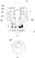
- An upper boss is disposed at the upper end of the inner surface of the torsional cover; a corresponding lower boss is disposed on the upper end face of the adjusting ring; and the lower boss is positioned on the right side of the upper boss.
- the impact conversion cushion includes a round ring and three poke rods which are uniformly distributed on the circumference of the round ring in a radiative way.
- Lock grooves corresponding to the poke rods, are formed at the upper end face of the adjusting ring.
- the tripping cushion is ring-shaped.
- the tripping cushion is internally provided with a plurality of limiting projections inwards.
- Lock grooves corresponding to the limiting projections, are formed at the lower end face of the adjusting ring.
- Horizontal lock platforms are formed among the lock grooves. When the adjusting ring locks the tripping cushion or the impact conversion cushion, the lock platforms contact the limiting projections or the poke rods.
- a plurality of bosses are disposed at the front end of the front gearbox housing, and the adjusting ring is sleeved below the bosses, so the adjusting ring cannot move up and down.
- each boss is formed with a limiting chute which extends along the vertical direction, and the poke rods are embedded in the limiting chutes.
- a positioning block is equipped above the adjusting screw; the top end of the positioning block is connected with the torsional cover; a chute is formed at the inner side of the adjusting screw along the vertical direction; a sliding portion matched with the chute is disposed at the lower end of the positioning block; and the adjusting screw is in sliding connection with the sliding portion of the positioning block.
- an output shaft penetrates the middle of the front gearbox housing; the bottom of the output shaft is connected with the reduction mechanism; the output shaft is sleeved with an impact structure; the round ring of the impact conversion cushion is sleeved on the output shaft; and the impact structure is disposed below the impact conversion cushion.
- a reset torsional spring is connected between the tripping cushion and the adjusting ring.
- the present invention has at least the following technical characteristics and progresses.
- a gear adjusting device for an electric impact drill consists of a front gearbox housing 1, a torsional cover 2 rotationally sleeved at the top of the front gearbox housing 1, a reduction mechanism 3 disposed at the bottom of the front gearbox housing 1 and a tripping structure disposed within the torsional cover 2.
- the tripping structure consists of an adjusting screw 4 in threaded connection with the torsional cover 2, a tripping cushion 42, an adjusting ring 43 and an impact conversion cushion 44.
- the adjusting screw 41 is connected with a plurality of vertical compression springs 45.
- the adjusting screw 41 is connected with one end of each of the plurality of vertical compression springs 45, and the other end of each of the compression springs 45 is connected with the tripping cushion 42.
- the tripping cushion 42, the adjusting ring 43 and the impact conversion cushion 44 are disposed on the front gearbox housing 1 in turn from the bottom up.
- a lock structure for locking the impact conversion cushion 44 is disposed at the upper end face of the adjusting ring 43.
- a lock structure for locking the tripping cushion 42 is disposed at the lower end face of the adjusting ring 43.
- An upper boss 21 is disposed at the upper end of the inner surface of the torsional cover 2; a corresponding lower boss 432 is disposed at the upper end face of the adjusting ring 43; and the lower boss 432 is positioned on the right side of the upper boss 21.
- the torsional cover 2 rotates to drive the adjusting screw 41 to move up and down.
- the vertical movement of the adjusting screw 41 changes the compression quantity of the compression springs 45 in connection with the adjusting screw 41.
- the torsional cover 2 outputs different torsions.
- the lower boss 432 is positioned on the right side of the upper boss 21, so when the torsional cover 2 rotates anticlockwise, the upper boss 21 positioned at the inner surface thereof drives the lower boss 432 to rotate, namely driving the adjusting ring 43 to rotate.
- the adjusting ring 43 locks the tripping cushion 42 and the impact conversion cushion 44, thereby presenting different states of the impact electric drill. Therefore, when the gear adjusting device is used for carrying out the adjustment, it is only needed to rotate the torsional cover 2 anticlockwise. In this way, the adjustment stroke is short, mode switching is achieved by one step, and inaccurate adjustment is avoided.
- the impact conversion cushion 44 includes a round ring 442 and three poke rods 441 which are uniformly distributed on the circumference of the round ring 442 in a radiative way.
- Lock grooves 431, corresponding to the poke rods 441, are formed at the upper end face of the adjusting ring 43.
- the tripping cushion is ring-shaped.
- the tripping cushion 42 is internally provided with a plurality of limiting projections 421 inwards.
- Lock grooves 431, corresponding to the limiting projections 421, are formed at the lower end face of the adjusting ring 43.
- Horizontal lock platforms 433 are formed among the lock grooves 431.
- the adjusting ring 43 locks the tripping cushion 42 or the impact conversion cushion 44
- the lock platforms 433 contact the limiting projections 421 or the poke rods 441.
- the lock grooves 431 contact the limiting projections 421 or the poke rods 441, the adjusting ring is in a non-locked state.
- the adjustment mechanism is as follows.
- the lock platforms 433 at the lower end face of the adjusting ring 43 rotate onto the limiting projections 421 of the tripping cushion 42, while the lock platforms 433 at the upper end face of the adjusting ring 43 still contact the poke rods 441.
- both tripping cushion 42 and impact conversion cushion 44 are locked, and the torsional cover 2 is positioned at an electric drill gear. If the torsional cover 2 is continuously rotated anticlockwise to drive the adjusting ring 43 to continue to rotate, the lock platforms at the lower end face of the adjusting ring 43 still contact the limiting projections 421 of the tripping cushion 42, and the lock grooves 431 at the upper end face of the adjusting screw 43 contact the poke rods 441.
- the tripping cushion 42 is locked, while the impact conversion cover 44 can move up and down in the lock grooves 431, so an impact structure 6 below the impact conversion cushion 44 achieves an impact effect, meaning that the torsional cover 2 is positioned at an impact gear.
- a plurality of bosses 11 are disposed at the front end of the front gearbox housing 1, and the adjusting ring 43 is disposed below the bosses 11, so the adjusting ring 43 cannot move up and down.
- the adjusting ring 43 changes positions of the lock grooves 431 at the upper and lower end faces thereof through rotation, driving the lock platforms 433 to press the tripping cushion 42 and/or the impact conversion cushion 44 to achieve the locking effect. If the adjusting ring 43 moves up and down, the lock platforms 433 cannot press the tripping cushion 42 and/or the impact conversion cushion 44, failing to achieve the locking effect and having the gear adjusting function blocked. Therefore, the arrangement of the bosses 11 can prevent the adjusting ring 43 from moving up and down.
- each boss 11 is formed with a limiting chute 111 which extends along the vertical direction, and the poke rods 441 are embedded in the limiting chutes 111.
- the poke rods 441 are embedded in the limiting chutes 111 so that the impact conversion cushion 44 can move up and down only.
- the adjusting screw 43 is positioned below the bosses 11, and the locking state of the impact conversion cushion 44 is decided by the fixing state of the poke rods 441 made by the adjusting ring 43, so the embedment of the poke rods 441 in the limiting chute 111 is good for control over the poke rods 441 by the adjusting rods 43.
- a positioning block 46 is equipped above the adjusting screw 41; the top end of the positioning block 46 is connected with the torsional cover 2; a chute 411 is formed at the inner side of the adjusting screw 41 along the vertical direction; a sliding portion 461 matched with the chute 411 is disposed at the lower end of the positioning block 46; and the adjusting screw 41 is in sliding connection with the sliding portion 461 of the positioning block 46.
- the torsional cover 2 is rotated to drive the adjusting screw 41 in connection with the torsional cover 2, and then the adjusting screw 41 moves to adjust the compression springs 45 in connection with the adjusting screw 41, so the torsional cover 2 realizes different torsion outputs according to the compression quantity of the compression springs 45.
- the adjusting screw 41 can move only in the vertical direction.
- the positioning block 46 plays the role of positioning the adjusting screw 41 in the horizontal direction. Due to the connection between the chute 411 and the sliding portion 461, the adjusting screw 41 can only move vertically along the direction in which the sliding portion 461 is disposed.
- the rotational torque thereof is directly converted into the vertical journey of the adjusting screw 41, bringing convenience to the adjustment of the torsion, thereby realizing the objective of the quick gear adjustment.
- an output shaft 5 penetrates the middle of the front gearbox housing 1; the bottom of the output shaft 5 is connected with the reduction mechanism 3; the output shaft 5 is sleeved with an impact structure 6; the round ring 442 of the impact conversion cushion 44 is sleeved on the output shaft 5; and the impact structure 6 is disposed below the impact conversion cushion 44.
- the impact conversion cushion 44 is locked by the adjusting ring 43, the impact structure 6 cannot conduct normal contact and is positioned at the screw gear or electric drill gear.
- the impact conversion cushion 44 When the impact conversion cushion 44 is not locked by the adjusting ring 43, the impact conversion cushion can axially move up and down, the impact structure 6 can perform normal contact, and at this time, the lower end face of the adjusting ring 43 locks the tripping cushion 42 such that the reduction mechanism 3 cannot trip. Then, the electric impact drill conducts the impacting function.
- a reset torsional spring 7 is connected between the tripping cushion 42 and the adjusting ring 43.
- the adjusting ring 43 automatically resets by the action force of the reset torsional spring 7 to facilitate adjustment to the gear in the next time.
Landscapes
- Engineering & Computer Science (AREA)
- Mechanical Engineering (AREA)
- Drilling And Boring (AREA)
Applications Claiming Priority (1)
| Application Number | Priority Date | Filing Date | Title |
|---|---|---|---|
| CN201610820974.3A CN106239433A (zh) | 2016-09-14 | 2016-09-14 | 一种冲击电钻档位调节装置 |
Publications (1)
| Publication Number | Publication Date |
|---|---|
| EP3296061A1 true EP3296061A1 (de) | 2018-03-21 |
Family
ID=57599887
Family Applications (1)
| Application Number | Title | Priority Date | Filing Date |
|---|---|---|---|
| EP17174023.6A Withdrawn EP3296061A1 (de) | 2016-09-14 | 2017-06-01 | Getriebeeinstellvorrichtung für elektroschlagbohrer |
Country Status (3)
| Country | Link |
|---|---|
| US (1) | US20180071905A1 (de) |
| EP (1) | EP3296061A1 (de) |
| CN (1) | CN106239433A (de) |
Families Citing this family (5)
| Publication number | Priority date | Publication date | Assignee | Title |
|---|---|---|---|---|
| JP7458167B2 (ja) * | 2019-11-08 | 2024-03-29 | 株式会社マキタ | 電動ドライバドリル |
| CN212445068U (zh) * | 2020-03-02 | 2021-02-02 | 群胜科技(苏州)有限公司 | 一种改良结构的无间隙主轴锁定装置 |
| US12311518B2 (en) | 2021-07-06 | 2025-05-27 | Nanjing Chervon Industry Co., Ltd. | Impact drill |
| CN115570181B (zh) * | 2021-07-06 | 2025-03-14 | 南京泉峰科技有限公司 | 多功能冲击钻 |
| CN115338833A (zh) * | 2022-08-24 | 2022-11-15 | 江苏大艺科技股份有限公司 | 一种电动工具 |
Citations (4)
| Publication number | Priority date | Publication date | Assignee | Title |
|---|---|---|---|---|
| EP1555091A2 (de) * | 2004-01-09 | 2005-07-20 | Makita Corporation | Bohrmaschine/kraftbetriebener Schrauber |
| US20060086514A1 (en) * | 2004-10-26 | 2006-04-27 | Bruno Aeberhard | Hand power tool, in particular drilling screwdriver |
| US20130333907A1 (en) * | 2010-12-22 | 2013-12-19 | Joachim Hecht | Hand-held power tool |
| US20140110140A1 (en) * | 2012-10-19 | 2014-04-24 | Milwaukee Electric Tool Corporation | Hammer drill |
Family Cites Families (5)
| Publication number | Priority date | Publication date | Assignee | Title |
|---|---|---|---|---|
| US6202759B1 (en) * | 2000-06-24 | 2001-03-20 | Power Network Industry Co., Ltd. | Switch device for a power tool |
| JP2008200802A (ja) * | 2007-02-20 | 2008-09-04 | Mura Technology:Kk | インパクト回転出力装置及びインパクト電動工具 |
| CN202239771U (zh) * | 2011-10-18 | 2012-05-30 | 东莞市妙达电动工具制造有限公司 | 一种新型多功能冲击电钻 |
| CN205057971U (zh) * | 2015-09-24 | 2016-03-02 | 东莞百事得电动工具有限公司 | 电动工具齿轮箱档位调节装置 |
| CN206216621U (zh) * | 2016-09-14 | 2017-06-06 | 群胜科技(苏州)有限公司 | 一种冲击电钻档位调节装置 |
-
2016
- 2016-09-14 CN CN201610820974.3A patent/CN106239433A/zh active Pending
- 2016-10-11 US US15/290,670 patent/US20180071905A1/en not_active Abandoned
-
2017
- 2017-06-01 EP EP17174023.6A patent/EP3296061A1/de not_active Withdrawn
Patent Citations (4)
| Publication number | Priority date | Publication date | Assignee | Title |
|---|---|---|---|---|
| EP1555091A2 (de) * | 2004-01-09 | 2005-07-20 | Makita Corporation | Bohrmaschine/kraftbetriebener Schrauber |
| US20060086514A1 (en) * | 2004-10-26 | 2006-04-27 | Bruno Aeberhard | Hand power tool, in particular drilling screwdriver |
| US20130333907A1 (en) * | 2010-12-22 | 2013-12-19 | Joachim Hecht | Hand-held power tool |
| US20140110140A1 (en) * | 2012-10-19 | 2014-04-24 | Milwaukee Electric Tool Corporation | Hammer drill |
Also Published As
| Publication number | Publication date |
|---|---|
| CN106239433A (zh) | 2016-12-21 |
| US20180071905A1 (en) | 2018-03-15 |
Similar Documents
| Publication | Publication Date | Title |
|---|---|---|
| EP3296061A1 (de) | Getriebeeinstellvorrichtung für elektroschlagbohrer | |
| CN106041502A (zh) | 一种伺服智能锁螺丝机构 | |
| DE102017109598A1 (de) | Kraftwerkzeug | |
| US20150135872A1 (en) | Impact switching device of an impact drill gearbox | |
| EP3362226B1 (de) | Handwerkzeugmaschine | |
| JPH03160917A (ja) | トリマ等の草刈装置 | |
| EP2457694A2 (de) | Handwerkzeugmaschine | |
| DE102017009211A1 (de) | Arbeitsmaschine und verfahren zum ermitteln eines abnormalen zustands der arbeitsmaschine | |
| WO2021094152A1 (de) | Verfahren zum steuern und regeln einer werkzeugmaschine und handgriff für werkzeugmaschine | |
| EP3822034A1 (de) | Verfahren zum steuern und regeln einer werkzeugmaschine | |
| EP2237841A1 (de) | Absturzsicherungsgerät mit seilantriebsmechanismus | |
| EP4058246A1 (de) | Verfahren zum steuern und regeln einer werkzeugmaschine | |
| CN204621991U (zh) | 冲击钻齿轮箱的档位调节装置 | |
| CN201098886Y (zh) | 具备工作模式快速切换装置的电动工具 | |
| CN101664832B (zh) | 换档式恒扭矩攻丝机构 | |
| KR20160006135A (ko) | 전동 실린더 | |
| TWM527815U (zh) | 衝擊鑽齒輪箱的檔位調節裝置 | |
| EP4058248A1 (de) | Handgriffvorrichtung für eine werkzeugmaschine | |
| CN104787638B (zh) | 棘爪能自动复位的双向限速器 | |
| CN107322054A (zh) | 一种便于操作的打孔机 | |
| KR20150108210A (ko) | 전동 실린더 | |
| US20090288850A1 (en) | Percussion Toggle Device of a Percussion Driller | |
| CN110645151B (zh) | 一种具有抗台风能力的风力发电设备 | |
| CN206216621U (zh) | 一种冲击电钻档位调节装置 | |
| CN210119673U (zh) | 旋底盖机 |
Legal Events
| Date | Code | Title | Description |
|---|---|---|---|
| PUAI | Public reference made under article 153(3) epc to a published international application that has entered the european phase |
Free format text: ORIGINAL CODE: 0009012 |
|
| AK | Designated contracting states |
Kind code of ref document: A1 Designated state(s): AL AT BE BG CH CY CZ DE DK EE ES FI FR GB GR HR HU IE IS IT LI LT LU LV MC MK MT NL NO PL PT RO RS SE SI SK SM TR |
|
| AX | Request for extension of the european patent |
Extension state: BA ME |
|
| 17P | Request for examination filed |
Effective date: 20180920 |
|
| RBV | Designated contracting states (corrected) |
Designated state(s): AL AT BE BG CH CY CZ DE DK EE ES FI FR GB GR HR HU IE IS IT LI LT LU LV MC MK MT NL NO PL PT RO RS SE SI SK SM TR |
|
| STAA | Information on the status of an ep patent application or granted ep patent |
Free format text: STATUS: THE APPLICATION IS DEEMED TO BE WITHDRAWN |
|
| 18D | Application deemed to be withdrawn |
Effective date: 20200103 |