EP3296094B1 - Pneumatische müllsammelvorrichtung - Google Patents
Pneumatische müllsammelvorrichtung Download PDFInfo
- Publication number
- EP3296094B1 EP3296094B1 EP16380034.5A EP16380034A EP3296094B1 EP 3296094 B1 EP3296094 B1 EP 3296094B1 EP 16380034 A EP16380034 A EP 16380034A EP 3296094 B1 EP3296094 B1 EP 3296094B1
- Authority
- EP
- European Patent Office
- Prior art keywords
- compactor
- refuse
- container
- module
- compacting
- Prior art date
- Legal status (The legal status is an assumption and is not a legal conclusion. Google has not performed a legal analysis and makes no representation as to the accuracy of the status listed.)
- Active
Links
Images







Classifications
-
- B—PERFORMING OPERATIONS; TRANSPORTING
- B30—PRESSES
- B30B—PRESSES IN GENERAL
- B30B9/00—Presses specially adapted for particular purposes
- B30B9/30—Presses specially adapted for particular purposes for baling; Compression boxes therefor
- B30B9/3042—Containers provided with, or connectable to, compactor means
-
- B—PERFORMING OPERATIONS; TRANSPORTING
- B65—CONVEYING; PACKING; STORING; HANDLING THIN OR FILAMENTARY MATERIAL
- B65F—GATHERING OR REMOVAL OF DOMESTIC OR LIKE REFUSE
- B65F1/00—Refuse receptacles; Accessories therefor
- B65F1/14—Other constructional features; Accessories
- B65F1/1405—Compressing means incorporated in, or specially adapted for, refuse receptacles
-
- B—PERFORMING OPERATIONS; TRANSPORTING
- B65—CONVEYING; PACKING; STORING; HANDLING THIN OR FILAMENTARY MATERIAL
- B65F—GATHERING OR REMOVAL OF DOMESTIC OR LIKE REFUSE
- B65F5/00—Gathering or removal of refuse otherwise than by receptacles or vehicles
- B65F5/005—Gathering or removal of refuse otherwise than by receptacles or vehicles by pneumatic means, e.g. by suction
-
- B—PERFORMING OPERATIONS; TRANSPORTING
- B65—CONVEYING; PACKING; STORING; HANDLING THIN OR FILAMENTARY MATERIAL
- B65F—GATHERING OR REMOVAL OF DOMESTIC OR LIKE REFUSE
- B65F2210/00—Equipment of refuse receptacles
- B65F2210/188—Vacuum drawing means
Definitions
- the present invention relates generally to a pneumatic refuse collection apparatus, and more particularly to a pneumatic collection apparatus which is capable of selectively collecting two different fractions and is constituted by three easily transportable modules having a compact design.
- a large amount of refuse is generated in some places, such as large buildings that are usually related to public access in general, for example hospitals, shopping centers, etc., and it would therefore be suitable to install pneumatic refuse collection apparatus in such places. Nevertheless, a drawback that these places have in general is that they have a small and limited space for installing the pneumatic refuse collection apparatus.
- An objective of the present invention is to provide a pneumatic refuse collection apparatus that can be divided into different compact, modular units which can be easily transported and coupled to one another, does not require a specific infrastructure for installation, and provides easy access to its mechanisms and to the control devices thereof.
- Patent document US 3889830 A discloses a pneumatic refuse collection apparatus comprising a container, a fan-based suction device, and a compacting ram-based compactor device that are installed in a single structure on the chassis of a truck.
- the container has only one compartment with a refuse inlet and an air outlet, the suction device is arranged such that it draws out air from inside the compartment through the air outlet and thereby generates a negative pressure which suctions the refuse inside the compartment through the refuse inlet, and the compactor device is arranged such that it compacts the refuse inside the compartment.
- Patent document DE 4400007 C1 describes a pneumatic refuse collection apparatus comprising a container and a suction device including a fan installed on the chassis of a truck.
- the container is provided with three compartments, each of which has a combined refuse and air inlet.
- the suction device suctions the refuse through an inlet duct and injects the refuse, together with the suction air, selectively into one of the compartments by means of a mobile transfer duct and through the corresponding combined refuse and air inlet.
- the outlet of the mobile transfer duct can be arranged to selectively face any one of the three combined refuse and air inlets of the three compartments.
- Patent document WO 2015092122 A1 discloses a pneumatic refuse collection apparatus 2-in accordance with the preamble of claim 1, comprising a container comprising a compartment having a refuse inlet, an air outlet and a compacting inlet, a compactor device comprising an air inlet, a compacting outlet, and a compacting ram which is moved by an actuator between a retracted position, in which the compacting ram is inside the compactor device, and an extended position, in which the compacting ram projects outwardly from the compactor coupling face through the compacting outlet, and a suction device comprising a fan arranged inside an enclosure having an air inlet and an air outlet, the suction device being arranged for drawing out air from inside the container through the air outlet of the container thereby generating a negative pressure which suctions the refuse inside the container through the refuse inlet thereof.
- the container has a container coupling face where the air outlet and the compacting inlet are located
- the compactor device has a compactor coupling face where the air inlet and the compacting outlet are located.
- the container coupling face of the container and the compactor coupling face of the compactor fit together for attaching the container to the compactor in an operative position in which the air outlet and the compacting inlet of the container are aligned and coupled with the air inlet and the compacting outlet of the compactor device, respectively, and the compacting ram is received in the extended position in the compartment of the container through the compacting outlet and the compacting inlet for compacting the refuse inside the container.
- Patent document JP S5312946 1A discloses a refuse container having a compartment with a refuse inlet and a compactor device having a refuse chamber with a refuse hopper inlet and a refuse outlet and a compacting ram which is moved inside the compactor device by an actuator between a retracted position, in which the compacting ram is away from the refuse outlet, and an extended position, in which the compacting ram is adjacent the refuse outlet.
- the container has a container coupling face provided with a door where the refuse inlet is located and the compactor device has a compactor coupling face where the refuse outlet is located. In an operative position, the container coupling face of the container is joined to the compactor coupling face of the compactor device and the refuse inlet is aligned and coupled with the refuse outlet.
- the present invention contributes to achieving the foregoing and other objectives by providing a pneumatic refuse collection apparatus in accordance with claim 1, comprising a container having a refuse inlet and an air outlet, a suction device drawing out air from inside the container through the air outlet, thereby generating a negative pressure which suctions the refuse inside the container through the refuse inlet, and a compactor device compacting the refuse inside the container.
- the container is integrated in a container module comprising a compartment having a refuse inlet, an air outlet and a compacting inlet.
- the container module has on one of its sides a container coupling face, and at least the air outlet and the compacting inlet are located on a container coupling face.
- the compactor device is integrated in a compactor-duct carrier module comprising an air inlet, an air outlet, an air duct communicating the air inlet with the air outlet, and a compacting ram which is moved by an actuator between a retracted position, in which the compacting ram is inside the compactor-duct carrier module, and an extended position, in which the compacting ram projects outwardly from the compactor-duct carrier module through the compacting outlet.
- the compactor-duct carrier module has installed therein a hydraulic unit, and the actuator moving the compacting ram is likewise a hydraulic cylinder operated by this hydraulic unit.
- the compactor-duct carrier module has on one of its sides a first compactor coupling face and on another opposite side a second compactor coupling face.
- the air inlet and the compacting outlet are located on the first compactor coupling face and the air outlet is located on the second compactor coupling face.
- the suction device is integrated in a suction module comprising a fan arranged inside an enclosure having an air inlet and an air outlet.
- the suction module has a suction coupling face in which the air inlet is located.
- the air inlet of the suction module can be coupled to the air outlet of the compactor-duct carrier module.
- the suction module comprises a cabin having an access door.
- the cabin houses the suction device and an electrical control panel.
- the fan is preferably a centrifugal fan having a blade impeller rotating about a horizontal axis, and the air inlet of the enclosure is aligned with the horizontal axis of rotation of the blade impeller, whereas the air outlet is in a position tangent to the blade impeller.
- An electric motor rotating the blade impeller of the fan is installed in the suction module.
- the container coupling face of the container module and the first compactor coupling face of the compactor-duct carrier module have elements that fit together and anchoring devices which, when activated, attach the container module and the compactor-duct carrier module to one another in an operative position, in which the air outlet and the compacting inlet of the container module are aligned and coupled with the air inlet and the compacting outlet of the compactor-duct carrier module, respectively.
- the compacting ram is therefore received in the extended position in the compartment of the container through the compacting outlet of the compactor-duct carrier module and the compacting inlet of the container module.
- the compactor-duct carrier module and the suction module are preferably provided for being supported on the ground and kept in a fixed position by friction.
- the compactor-duct carrier module and/or the suction module comprise legs provided with fixing elements which allow fixing the compactor-duct carrier module and/or the suction module to the ground in the mentioned fixed position.
- the container module is preferably provided with rolling elements for rolling on the ground, and optionally these rolling elements have surfaces that are coupled to alignment rails fixed to the ground in positions adjacent to the compactor-duct carrier module. Therefore, when the container module is moved closer to the compactor-duct carrier module by rolling it on the ground, the alignment rails align the container module with the compactor-duct carrier module and secure the coupling thereof to one another in the operative position.
- the anchoring devices comprise protruding elements fixed in the container module and retractable hooks installed in the compactor-duct carrier module.
- the retractable hooks hook onto the protruding elements of the container module and are retracted by respective actuators for pressing the container coupling face of the container module against the first compactor coupling face of the compactor-duct carrier module.
- the actuators retracting the retractable hooks are hydraulic cylinders operated by the hydraulic unit installed in the compactor-duct carrier module, although alternatively they could be actuators based on a manually operated lever.
- the refuse inlet of the compartment of the container module is located on the container coupling face of the container module and the compactor-duct carrier module further comprises a refuse outlet located on the first compactor coupling face and a refuse inlet.
- the refuse inlet of the container module is aligned and coupled with the refuse outlet of the compactor-duct carrier module.
- the container module preferably comprises a door that can be moved between an open position, in which the door provides access to the compartment of the container, and a closed position, in which the door closes the compartment and provides the container coupling face.
- the refuse inlet, the air outlet and the compacting inlet are formed in the door.
- the container module comprises a second compartment having a second refuse inlet, a second air outlet and a second compacting inlet, wherein at least the second air outlet and the second compacting inlet are located on the container coupling face.
- the compactor-duct carrier module comprises a second air inlet and a second compacting outlet located on the first compactor coupling face, a second air duct communicating the second air inlet with the air outlet by means of a collector to which there is also connected the first air duct, and a second compacting ram which is moved by a second actuator between a retracted position, in which the second compacting ram is inside the compactor-duct carrier module, and an extended position, in which the second compacting ram projects outwardly from the first compactor coupling face through the second compacting outlet.
- the actuators moving the first and second compacting rams can act simultaneously with or independently of one another, and in a particular embodiment, the actuators are hydraulic cylinders operated by the hydraulic unit installed in the compactor-duct carrier module.
- the first and second air outlets and the first and second compacting inlets of the container module are aligned and coupled with the first and second air inlets and the first and second compacting outlets of the compactor-duct carrier module, respectively, and the first and second compacting rams in the extended position are received in the first and second compartments of the container through the first and second compacting outlets of the compactor-duct carrier module and the first and second compacting inlets of the container module.
- the first air duct of the compactor-duct carrier module has a first shutter that can be moved between an open position and a closed position
- the second air duct of the compactor-duct carrier module has a second shutter that can be moved between an open position and a closed position.
- the first and second shutters are moved by respective actuators, such as, for example, hydraulic cylinders operated by the hydraulic unit installed in the compactor-duct carrier module, although alternatively the actuators moving the first and second shutters could be manually operated actuators.
- the first and second refuse inlets of the first and second compartments of the container module are also preferably located on the container coupling face.
- the compactor-duct carrier module further comprises first and second refuse outlets located on the first compactor coupling face, a refuse inlet, a refuse duct having a first end connected to the refuse inlet, and a distributor device communicating a second end of the refuse duct selectively with either the first or second refuse outlets, so the distributor device allows selecting two different refuse fractions and storing them separately in the two compartments of the container module.
- the first and second refuse inlets of the container module are aligned and coupled with the first and second refuse outlets of the compactor-duct carrier module when the container module and the compactor-duct carrier module are attached to one another in the operative position.
- the first and second ends of the refuse duct are misaligned with respect to one another, the first end of the refuse duct is connected to the refuse inlet by a rotary joint and the distributor device comprises a rocker arm fixed to the second end of the refuse duct and an actuator causing the rocker arm and the refuse duct to pivot about a shaft between first and second positions, in which the second end of the refuse duct is facing and in communication with the first and second refuse outlets, respectively.
- the actuator causing the rocker arm to pivot is preferably a hydraulic cylinder operated by the hydraulic unit installed in the compactor-duct carrier module, although alternatively it could be a manually operated actuator.
- the container module comprises first and second doors that can be moved between respective open positions, in which the first and second doors provide access to the first and second compartments of the container, respectively, and respective closed positions, in which the first and second doors close the first and second compartments, respectively.
- the first and second doors together provide the container coupling face when they are in the closed position, and the first and second refuse inlets, the first and second air outlets and the first and second compacting inlets are formed in the first and second doors, respectively.
- the refuse inlet of the compactor-duct carrier module is located on the second compactor coupling face
- the suction module comprises a refuse duct having a refuse outlet located on the suction coupling face and a refuse inlet.
- the refuse outlet can be connected to the refuse inlet located on the second compactor coupling face of the compactor-duct carrier module.
- the compactor-duct carrier module there is formed in the compactor-duct carrier module a refuse chamber demarcated between the compacting ram, when it is in the retracted position, and the compacting outlet, and the refuse duct opens directly into this refuse chamber instead of being connected to a refuse outlet.
- the compacting outlet therefore constitutes a refuse and compacting outlet through which the compacting ram transfers the refuse into the compartment of the container module and compacts said refuse in the compartment.
- the refuse inlet and the compacting inlet of the container module are combined constituting a refuse and compacting inlet located on the container coupling face of the container module, such that the refuse and compacting inlet of the container module is aligned and coupled with the refuse and compacting outlet of the compactor-duct carrier module when the container module and the compactor-duct carrier module are attached to one another in the operative position.
- first and second refuse chambers demarcated between the first and second compacting rams, when they are in the retracted positions, and the first and second compacting outlets
- the distributor device communicates the refuse duct selectively with either the first or second additional refuse ducts opening directly into the first and second refuse chambers, respectively.
- the first and second refuse outlets and the first and second compacting outlets are therefore combined forming first and second refuse and compacting outlets.
- first and second refuse inlets and the first and second compacting inlets of the first and second compartments of the container module are combined constituting respective first and second refuse and compacting inlets located on the container coupling face.
- These first and second refuse and compacting inlets are aligned and coupled with the first and second refuse and compacting outlets of the compactor-duct carrier module when the container module and the compactor-duct carrier module are attached to one another in the operative position.
- the distributor device in the compactor-duct carrier module, can be installed in an inclined position such that the distributed refuse outlets of the device are inclined towards the first compacting coupling face for the purpose of reducing a bend that the first and second additional refuse ducts must have in order to open into refuse inlets located in an upper part of the first and second refuse chambers.
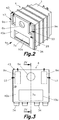
- reference number 100 generally designates a pneumatic refuse collection apparatus according to a first embodiment of the present invention provided for the collection of one refuse fraction, comprising a container module 4, a compactor-duct carrier module 5 and a suction module 6 operatively attached and coupled to one another.
- the container module 4 integrates a container 1 comprising only one compartment 7a with a door 40a articulated with respect to a jamb of the door frame of the container 1 by vertical hinges.
- the door 40a can be moved between an open position ( Figure 5 ), in which the door 40a provides access to the compartment 7a of the container 1, and a closed position ( Figures 2, 3 and 4 ), in which the door 40a closes the compartment 7a.
- the door 40a can be locked in the closed position by means of a lock 43.
- the door 40a When it is in the closed position, the door 40a provides a container coupling face 4a on which the refuse inlet 8a, the air outlets 9a and the compacting inlet 10a, which are in communication with the only compartment 7a, are arranged.
- the container module 4 has on its outer surface protruding elements 29 that are formed in the illustrated example by jambs of the door frame, and is provided with rolling elements 34 provided for rolling on the ground.
- the protruding elements 29 are part of anchoring devices for connecting the container module 4 and the compactor-duct carrier module 5.
- the container module 4 is configured for being handled and transported by a truck or another vehicle.
- the compactor-duct carrier module 5 (better shown in Figures 6 to 9 ) has opposing first and second compactor coupling faces 5a, 5b.
- a pair of air inlets 11a, a refuse outlet 14a and a compacting outlet 38a are located on the first compactor coupling face 5a.
- An air outlet 12 is located on the second compactor coupling face 5b.
- a pair of air ducts 13a communicates the air inlets 11a with the air outlet 12 through a collector 13c.
- a refuse duct 16 has a first end provided with a refuse inlet 15 provided with connecting elements (not shown) for connection thereof to a refuse delivery duct (not shown) and a second end connected to the refuse outlet 14a.
- the compactor-duct carrier module 5 has only one air inlet 11a on its first compactor coupling face 5a, and only one air duct 13a communicates the only air inlet 11a with the air outlet 12 located on the second compactor coupling face 5b.
- the compactor-duct carrier module 5 further comprises a compactor device 2 including a compacting ram 18a.
- An actuator such as, for example, a hydraulic cylinder 30a operated by a hydraulic unit 32, moves the compacting ram 18a between a retracted position (shown by means of solid lines in Figure 9 ), in which the compacting ram 18a is inside the compactor-duct carrier module 5 without projecting from the compacting outlet 38a, and an extended position (shown by means of dashed lines in Figure 9 ), in which the compacting ram 18a projects outwardly from the first compactor coupling face 5a through the compacting outlet 38a.
- Retractable hooks 28 connected to hydraulic cylinders 42 which are operated by the hydraulic unit 32 are installed on both sides of the compactor-duct carrier module 5. Activation of the hydraulic cylinders 42 retracts the retractable hooks 28, which are part of the anchoring devices and which cooperate with the protruding elements 29 of the container module 4.
- the hydraulic unit 32 is installed in a structure of the compactor-duct carrier module 5.
- the compactor-duct carrier module 5 has a hydraulic connection for being connected to an external hydraulic unit.
- the compactor-duct carrier module 5 comprises legs 35 provided with fixing elements, such as, for example, holes, for fixing the compactor-duct carrier module 5 to the ground by means of screws or bolts.
- the suction module 6 (better shown in Figures 10 to 13 ) comprises a cabin 52 provided with an access door 37 on one side and a suction coupling face 6a on another opposing side.
- a suction device 3 and an electrical control panel 36 are housed in the cabin 52.
- the suction device 3 comprises a fan having a blade impeller 19 arranged inside an enclosure 20 provided with an air inlet 21 located on the suction coupling face 6a and an air outlet 22 located in an upper position.
- the blade impeller 19 rotates about a horizontal axis being driven by an electric motor 33 installed in the cabin 52, the air inlet 21 of the enclosure 20 is aligned with the horizontal axis of rotation of the blade impeller 19 and the air outlet 22 is located in a position tangent to the blade impeller 19.
- the container module 4, the compactor-duct carrier module 5 and the suction module 6 form compact units sized for being transported individually by normal means of transport and for being operatively installed in relatively small places, such as basements of large buildings, such as, for example, hospitals, shopping centers, etc.
- the compactor-duct carrier module 5 When the modules are operatively installed ( Figure 1 ), the compactor-duct carrier module 5 is fixed to the ground by means of the fixing elements provided in its legs 35.
- the suction module 6 is placed on the ground with its suction coupling face 6a facing the second compacting coupling face 5b of the compactor-duct carrier module 5.
- the air inlet 21 of the suction module 6 is aligned with the air outlet 12 of the compactor-duct carrier module 5 and coupled to the air outlet 12 by means of a flange 49.
- the air outlet 22 of the suction module 6 is coupled to an air discharge duct (not shown) by means of a flange 44.
- the container module 4 is moved closer to the compactor-duct carrier module 5 by rolling it on the ground to an operative position, in which the container coupling face 4a of the container module 4 is facing the first compactor coupling face 5a of the compactor-duct carrier module 5.
- the refuse inlet 8a, the air outlets 9a and the compacting inlet 10a of the container module 4 are positioned such that, in the operative position, they are aligned and coupled with the refuse outlet 14a, the air inlets 11a and the compacting outlet 38a compactor-duct carrier module 5, respectively.
- Alignment rails 41 ( Figure 1 ) are preferably fixed on the ground in positions adjacent to the first compactor coupling face 5a of the compactor-duct carrier module 5.
- the rolling elements 34 of the container module 4 have surfaces that are coupled to the alignment rails 41 for directing the container module 4 towards the compactor-duct carrier module 5 in the operative position.
- the refuse outlet 14a, the air inlets 11a and the compacting outlet 38a of the compactor-duct carrier module 5 are provided with respective perimetral protrusions that respectively enter the refuse inlet 8a, the air outlets 9a and the compacting inlet 10a of the container module 4 in the operative position, constituting elements that fit together.
- the air inlets 11a and the refuse outlet 14a of the compactor-duct carrier module 5 have perimetral fins 46, 47 that are supported against the door 40a of the container module 4 compressing respective elastic joints in the operative position.
- the first compactor coupling face 5a of the compactor-duct carrier module 5 has a support surface 45 which is supported against the door 40a of the container module 4 in the operative position.
- the retractable hooks 28 of the compactor-duct carrier module 5 hook onto the protruding elements 29 of the container module 4 and are retracted by the hydraulic cylinders 42 for pressing the container coupling face 4a of the container module 4 against the first compactor coupling face 5a of the compactor-duct carrier module 5 and for keeping both modules coupled to one another in the operative position.
- Additional anchoring elements such as manually operated levers 53 that can be snapped closed, are arranged for securing the perimetral fins 46 of the air inlets 11a of the compactor-duct carrier module 5 against the door 40a of the container module 4.
- the suction device 3 of the suction module 6 draws out air from inside the compartment 7a of the container 1 of the container module 1 through the air outlets 11a, thereby generating a negative pressure which suctions the refuse inside the compartment 7a of the container 1 through the refuse inlet 8a.
- the compacting ram 18a of the compactor device 2 of the compactor-duct carrier module 5 enters the compartment 7a of the container 1 of the container module 4 through the compacting inlet 10a and compacts the refuse inside the container 1.
- reference number 200 generally designates a pneumatic refuse collection apparatus according to a second embodiment of the present invention provided for the collection of two different refuse fractions, comprising a container module 4, a compactor-duct carrier module 5 and a suction module 6 operatively attached and coupled to one another.
- the container module 4, the compactor-duct carrier module 5 and the suction module 6 are similar to those described above in relation to the first embodiment except in the following aspects.
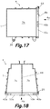
- the container module 4 comprises a partition 48 dividing the container 1 into first and second compartments 7a, 7b provided with respective first and second doors 40a, 40b in which respective first and second refuse inlets 8a, 8b, first and second air outlets 9a, 9b and first and second compacting inlets 10a, 10b are formed.
- the first and second doors 40a, 40b are articulated with respect to opposite jambs of the door frame of the container 1 by vertical hinges and can be moved between open positions ( Figure 19 ) and closed positions ( Figures 15, 16 and 18 ).
- first and second doors 40a, 40b When they are in the closed positions, the first and second doors 40a, 40b together provide a container coupling face 4a, such that the first and second refuse inlets 8a, 8b, the first and second air outlets 9a, 9b and the first and second compacting inlets 10a, 10b are located on the container coupling face 4a.
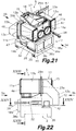
- the compactor-duct carrier module 5 comprises first and second air inlets 11a, 11b, first and second refuse outlets 14a, 14b, and first and second compacting outlets 38a, 38b located on the first compactor coupling face 5a, in addition to the air outlet 12 located on the second compactor coupling face 5a.
- First and second air ducts 13a, 13b communicate the first and second air inlets 11a, 11b with the air outlet 12 by means of a collector 13c.
- the first air duct 13a of the compactor-duct carrier module 5 has a first shutter 23a that can be moved between an open position and a closed position
- the second air duct 13b of the compactor-duct carrier module 5 has a second shutter 23b that can be moved between an open position and a closed position.
- the first and second shutters 23a, 23b are moved by respective hydraulic cylinders 29a, 29b, although alternatively they could be manually operated.
- the compactor-duct carrier module 5 further comprises a refuse inlet 15 located on the first compactor coupling face 5a and a refuse duct 16 having a first end connected to the refuse inlet 15 and a second end connected to a distributor device 17 communicating the second end of the refuse duct 16 selectively with either the first or second refuse outlets 14a, 14b.
- the distributor device 17 acts for selecting two different refuse fractions.
- the first and second ends of the refuse duct 16 are misaligned with respect to one another although they are preferably parallel.
- the first end of the refuse duct 16 is connected to the refuse inlet 15 by a rotary joint and the distributor device 17 comprises a rocker arm 27 fixed to the second end of the refuse duct 16.
- An actuator such as, for example, a hydraulic cylinder 31, causes the rocker arm 27 and the refuse duct 16 to pivot about a shaft 27a between first and second positions, in which the second end of the refuse duct 16 is facing and in communication with the first and second refuse outlets 14a, 14b, respectively ( Figures 25 and 26 ).
- the compactor device 2 comprises first and second compacting rams 18a, 18b which are independently moved by respective first and second hydraulic cylinders 30a, 30b between a retracted position (shown by means of solid lines in Figure 24 ), in which the first and second compacting rams 18a, 18b are inside the compactor-duct carrier module 5, and an extended position (shown by means of dashed lines in Figure 24 ), in which the first and second compacting rams 18a, 18b project outwardly from the first compactor coupling face 5a through the corresponding first and second compacting outlets 38a, 38b.
- the first and second refuse inlets 8a, 8b, the first and second air outlets 9a, 9b and the first and second compacting inlets 10a, 10b of the container module 4 are aligned and coupled with the first and second refuse outlets 14a, 14b, the first and second air inlets 11a, 11b and the first and second compacting outlets 38a, 38b of the compactor-duct carrier module 5, respectively, and when they are in the extended position, the first and second compacting rams 18a, 18b are received in the first and second compartments 7a, 7b of the container 1 through the first and second compacting outlets 38b and the first and second compacting inlets 10a, 10b.
- the refuse inlet 15 of the compactor-duct carrier module 5 which is located on the second compactor coupling face 5b,
- the suction module 6 comprises, in addition to the elements already described in relation to the first embodiment, a refuse duct 24 having a refuse outlet 25 located on the suction coupling face 6a and a refuse inlet 26 located above the access door 37.
- the refuse duct 24 goes through the cabin 52 above the enclosure 20 of the fan.
- the refuse outlet 25 of the suction module 6 is connected to the refuse inlet 15 of the compactor-duct carrier module 5 by means of a flange 50.
- the refuse inlet 26 of the suction module 6 can be connected to a refuse delivery duct (not shown) by means of a flange 51.
- the hydraulic cylinders 30a, 30b which move the first and second compacting rams 18a, 18b, the hydraulic cylinders 29a, 29b which move the first and second shutters 23a, 23b and the hydraulic cylinder 31 which causes the rocker arm 27 to pivot are operated by a hydraulic unit 32 installed in the compactor-duct carrier module 5 or by an external hydraulic unit.
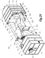
- reference number 300 generally designates a pneumatic refuse collection apparatus according to a third embodiment of the present invention provided for the collection of two different refuse fractions, and comprising a container module 4, a compactor-duct carrier module 5 and a suction module 6 operatively attached and coupled to one another.
- the suction module 6 is identical to that described above in relation to the second embodiment, whereas the container module 4 and the compactor-duct carrier module 5 only differ from what have been described in relation to the second embodiment as regards the features described below.
- the compactor device 2 of the compactor-duct carrier module 5 comprises first and second refuse chambers 54a, 54b which are comprised between the first and second compacting rams 18a, 18b, when they are in the retracted position, and the first and second compacting outlets 38a, 38b, and first and second additional refuse ducts 55a, 55b communicating outlets of the distributor device 17 with inlets of the first and second refuse chambers 54a, 54b located in an upper part thereof.
- the distributor device 17 communicates the refuse duct 16 selectively with either the first or second additional refuse ducts 55a, 55b for distributing the refuse to either the first or second refuse chambers 54a, 54b, respectively.
- the first and second refuse outlets 14a, 14b are combined with the first and second compacting outlets 38a, 38b constituting first and second refuse and compacting outlets 14a, 38a; 14b, 28b.
- the first and second compartments 7a, 7b have the respective first and second refuse inlets 8a, 8b and first and second compacting inlets 10a, 10b combined with one another constituting respective first and second refuse and compacting inlets 8a, 10a; 8b, 10b located on the container coupling face 4a.
- These first and second refuse and compacting inlets 8a, 10a; 8b, 10b are aligned and coupled with the first and second refuse and compacting outlets 14a, 38a; 14b, 38b of the compactor-duct carrier module 5 when the container module 4 and the compactor-duct carrier module 5 are attached to one another in the operative position.
- the container module 4 of the third embodiment comprises first and second doors 40a, 40b that can be moved between respective open and closed positions, and these first and second doors 40a, 40b, when they are in the closed positions, together provide the container coupling face 4a.
- the first and second refuse and compacting inlets 8a, 10a; 8b, 10b and the first and second air outlets 9a, 9b are formed in the first and second doors 40a, 40b, respectively.
- the compactor device has a refuse chamber and the refuse duct introduces the refuse directly in the refuse chamber, such that the refuse outlet and the compacting outlet of the compactor-duct carrier module are combined into a single refuse and compacting outlet, and the refuse inlet and the compacting inlet of the container module are combined into a single refuse and compacting inlet which is aligned and coupled with the refuse and compacting outlet of the compactor-duct carrier module when both modules are coupled in the operative position.
Landscapes
- Engineering & Computer Science (AREA)
- Mechanical Engineering (AREA)
- Refuse Collection And Transfer (AREA)
Claims (15)
- Pneumatische Müllsammelvorrichtung umfassend:einen Behälter (1), welcher in ein Behältermodul (4) integriert ist, umfassend eine Abteilung (7a), welche einen Behältermülleingang (8a), einen Behälterluftausgang (9a) und einen Verdichtungseingang (10a) aufweist, wobei sich mindestens der genannte Behälterluftausgang (9a) und der genannte Verdichtungseingang (10a) auf einer Behälterkopplungsfläche (4a) befinden;eine Verdichtereinrichtung (2) umfassend einen Verdichtungsausgang (38a), welcher sich auf einer ersten Verdichterkopplungsfläche (5a) befindet, und einen Verdichtungsstempel (18a), welcher von einem Stellglied zwischen einer eingefahrenen Stellung, in welcher der Verdichtungsstempel (18a) innerhalb des Verdichterleitungsträgermoduls (5) liegt, und einer ausgefahrenen Stellung, in welcher der Verdichtungsstempel (18a) von der genannten ersten Verdichterkopplungsfläche (5a) durch den genannten Verdichtungsausgang (38a) nach außen herausragt, bewegt wird;eine Saugeinrichtung (3) umfassend ein Gebläse, welches innerhalb eines Gehäuses (20) angeordnet ist, welches einen Sauglufteingang (21) und einen Saugluftausgang (22) aufweist, wobei die Saugeinrichtung (3) dazu ausgebildet ist, Luft aus dem Inneren des Behälters (1) durch den genannten Behälterluftausgang (9a) des Behältermoduls (4) herauszunehmen, wodurch ein Unterdruck erzeugt wird, welcher den Müll innerhalb des Behälters (1) durch den genannten Behältermülleingang (8a) des Behältermoduls (4) saugt;wobei die genannte Behälterkopplungsfläche (4a) des Behältermoduls (4) und die genannte erste Verdichterkopplungsfläche (5a) des Verdichterleitungsträgermoduls (5) Elemente aufweisen, welche zusammenpassen, und Verankerungseinrichtungen aufweisen, welche, wenn sie aktiviert werden, das Behältermodul (4) und das Verdichterleitungsträgermodul (5) in einer Betriebsstellung aneinander befestigen, in welcher der Verdichtungseingang (10a) des Behältermoduls (4) mit dem Verdichtungsausgang (38a) des Verdichterleitungsträgermoduls (5) ausgerichtet und gekoppelt ist, und der Verdichtungsstempel (18a) in der ausgefahrenen Stellung in der Abteilung (7a) des Behälters (1) durch den Verdichtungsausgang (38a) und den Verdichtungseingang (10a) zur Verdichtung des Mülls innerhalb des Behälters (1) aufgenommen wird,dadurch gekennzeichnet, dass:die Verdichtereinrichtung (2) in ein Verdichterleitungsträgermodul (5) integriert ist, zusätzlich umfassend eine Verdichterleitungsträgerlufteingang (11a), welcher sich auf der ersten Verdichterkopplungsfläche (5a) befindet, einen Verdichterleitungsträgerluftausgang (12), welcher sich auf einer zweiten, zur ersten Verdichterkopplungsfläche (5a) gegenüberliegenden und parallelen Verdichterkopplungsfläche (5b) befindet, und eine Luftleitung (13a), welche den genannten Verdichterleitungsträgerlufteingang (11a) mit dem genannten Verdichterleitungsträgerluftausgang (12) verbindet,
unddie Saugeinrichtung (3) in ein Saugmodul (6) integriert ist, welches eine Saugkopplungsfläche (6a) aufweist, in welcher sich der genannte Sauglufteingang (21) befindet, wobei die Saugkopplungsfläche (6a) des Saugmoduls (6) der zweiten Verdichtungskopplungsfläche (5b) des Verdichterleitungsträgermoduls (5) zugewandt ist und der Sauglufteingang (21) des Saugmoduls (6) mit dem Verdichterleitungsträgerluftausgang (12) des Verdichterleitungsträgermoduls (5) ausgerichtet ist und mit dem Verdichterleitungsträgerluftausgang (12) mittels eines Flansches (49) gekoppelt ist. - Pneumatische Müllsammelvorrichtung nach Anspruch 1, wobei sich der genannte Behältermülleingang (8a) des Behältermoduls (4) auf der Behälterkopplungsfläche (4a) des Behältermoduls (4) befindet, das Verdichterleitungsträgermodul (5) zusätzlich umfassend einen Verdichterleitungsträgermüllausgang (14a), welcher sich auf der ersten Verdichterkopplungsfläche (5a) befindet, einen Verdichterleitungsträgermülleingang (15) und eine Müllleitung (16), welche ein erstes Ende, welches mit dem genannten Verdichterleitungsträgermülleingang (15) verbunden ist, und ein anderes Ende, welches mit dem genannten Verdichterleitungsträgermüllausgang (14a) verbunden ist, aufweist, und der Behältermülleingang (8a) des Behältermoduls (4) mit dem genannten Verdichterleitungsträgermüllausgang (14a) des Verdichterleitungsträgermoduls (5) ausgerichtet und gekoppelt ist, wenn das Behältermodul (4) und das Verdichterleitungsträgermodul (5) in der Betriebsstellung aneinander befestigt sind.
- Pneumatische Müllsammelvorrichtung nach Anspruch 2, wobei das Behältermodul (4) eine Tür (40a) umfasst, welche zwischen einer offenen Stellung, in welcher die genannte Tür (40a) Zugang zur Abteilung (7a) des Behälters (1) bereitstellt, und einer geschlossenen Stellung, in welcher die Tür (40a) die Abteilung (7a) schließt und die Behälterkopplungsfläche (4a) bereitstellt, bewegt werden kann, und wobei der Behältermülleingang (8a), der Behälterluftausgang (9a) und der Verdichtungseingang (10a) in der genannte Tür (40a) gebildet sind.
- Pneumatische Müllsammelvorrichtung nach Anspruch 1, das Verdichterleitungsträgermodul (5) zusätzlich umfassend eine Müllkammer (54a), welche zwischen dem Verdichtungsstempel (18a) in der eingefahrenen Stellung und dem Verdichtungsausgang (38a) eingeschlossen ist, und eine Müllleitung (16), welche ein erstes Ende, welches mit einem Verdichterleitungsträgermülleingang (15) verbunden ist, und ein anderes Ende, welches mit der genannten Müllkammer (54a) verbunden ist, aufweist, wobei der Verdichtungsausgang (38a) einen Müll- und Verdichtungsausgang (14a, 38a) bildet, und der genannte Behältermülleingang (8a) des Behältermoduls (4) mit dem Verdichtungseingang (10a) kombiniert ist, unter Bildung des Müll- und Verdichtungseingangs (8a, 10a), welcher sich auf der Behälterkopplungsfläche (4a) des Behältermoduls (4) befindet, wobei der genannte Müll- und Verdichtungseingang (8a, 10a) mit dem Müll- und Verdichtungsausgang (14a, 38a) des Verdichterleitungsträgermoduls (5) ausgerichtet und gekoppelt ist, wenn das Behältermodul (4) und das Verdichterleitungsträgermodul (5) in der Betriebsstellung aneinander befestigt sind.
- Pneumatische Müllsammelvorrichtung nach Anspruch 4, wobei das Behältermodul (4) eine Tür (40a) umfasst, welche zwischen einer offenen Stellung, in welcher die genannte Tür (40a) Zugang zur Abteilung (7a) des Behälters (1) bereitstellt, und einer geschlossenen Stellung, in welcher die Tür (40a) die Abteilung (7a) schließt und die Behälterkopplungsfläche (4a) bereitstellt, bewegt werden kann, und wobei der Müll- und Verdichtungseingang (8a, 10a) und der Behälterluftausgang (9a) in der genannten Tür (40a) gebildet sind.
- Pneumatische Müllsammelvorrichtung nach Anspruch 1, wobei:das Behältermodul (4) eine zweite Abteilung (7b) umfasst, welche einen zweiten Behältermülleingang (8b), einen zweiten Behälterluftausgang (9b) und einen zweiten Verdichtungseingang (10b) aufweist, wobei sich mindestens der genannte Behälterluftausgang (9b) und der genannte Verdichtungseingang (10b) auf der Behälterkopplungsfläche (4a) befinden;das Verdichterleitungsträgermodul (5) umfassend einen zweiten Verdichterleitungsträgerlufteingang (11b) und einen zweiten Verdichtungsausgang (38b), welche sich auf der ersten Verdichterkopplungsfläche (5a) befinden, eine zweite Luftleitung (13b), welche den genannten zweiten Verdichterleitungsträgerlufteingang (11b) mit dem genannten Verdichterleitungsträgerluftausgang (12) mittels eines Sammlers (13c) verbindet, und einen zweiten Verdichtungsstempel (18b), welcher von einem zweiten Stellglied zwischen einer eingefahrenen Stellung, in welcher der zweite Verdichtungsstempel (18b) innerhalb des Verdichterleitungsträgermoduls (5) liegt, und einer ausgefahrenen Stellung, in welcher der zweite Verdichtungsstempel (18b) von der genannten ersten Verdichterkopplungsfläche (5a) durch den genannten zweiten Verdichtungsausgang (38b) nach außen herausragt, bewegt wird; undwenn das Behältermodul (4) und das Verdichterleitungsträgermodul (5) in der genannten Betriebsstellung aneinander befestigt sind, der zweite Behälterluftausgang (9b) und der zweite Verdichtungseingang (10b) des Behältermoduls (4) jeweils mit dem zweiten Verdichterleitungsträgerlufteingang (11b) und dem zweiten Verdichtungsausgang (38b) des Verdichterleitungsträgermoduls (5) ausgerichtet und gekoppelt sind, und der zweite Verdichtungsstempel (18b) in der ausgefahrenen Stellung in der zweiten Abteilung (7b) des Behälters (1) durch den zweiten Verdichtungsausgang (38b) und den zweiten Verdichtungseingang (10b) aufgenommen wird.
- Pneumatische Müllsammelvorrichtung nach Anspruch 6, wobei die erste Luftleitung (13a) des Verdichterleitungsträgermoduls (5) eine erste Blende (23a) aufweist, welche zwischen einer offenen Stellung und einer geschlossenen Stellung bewegt werden kann, und die zweite Luftleitung (13b) des Verdichterleitungsträgermoduls (5) eine zweite Blende (23b) aufweist, welche zwischen einer offenen Stellung und einer geschlossenen Stellung bewegt werden kann, und wobei die erste und die zweite Blende (23a, 23b) von jeweiligen Stellgliedern bewegt werden.
- Pneumatische Müllsammelvorrichtung nach Anspruch 6 oder 7, das Verdichterleitungsträgermodul (5) zusätzlich umfassend erste und zweite Verdichterleitungsträgermüllausgänge (14a, 14b), welche sich auf der ersten Verdichterkopplungsfläche (5a) befinden, einen Mülleingang (15), eine Müllleitung (16), welche ein erstes Ende aufweist, welches mit dem genannten Verdichterleitungsträgermülleingang (15) verbunden ist, und eine Verteilereinrichtung (17), welche ein zweites Ende der genannten Müllleitung (16) selektiv mit entweder dem ersten oder dem zweiten Verdichterleitungsträgermüllausgang (14a, 14b) verbindet, wobei sich der genannte erste und der genannte zweite Behältermülleingang (8a, 8b) der ersten und der zweiten Abteilung (7a, 7b) des Behältermoduls (4) auf der Behälterkopplungsfläche (4a) befinden und mit dem genannten ersten und dem genannten zweiten Verdichterleitungsträgermüllausgang (14a, 14b) des Verdichterleitungsträgermoduls (5) ausgerichtet und gekoppelt sind, wenn das Behältermodul (4) und das Verdichterleitungsträgermodul (5) in der Betriebsstellung aneinander befestigt sind.
- Pneumatische Müllsammelvorrichtung nach Anspruch 8, wobei das Behältermodul (4) erste und zweite Türen (40a, 40b) umfasst, welche zwischen jeweiligen offenen Stellungen, in welchen die genannten ersten und zweiten Türen (40a, 40b) Zugang jeweils zur ersten und zweiten Abteilung (7a, 7b) des Behälters (1) bereitstellen, und jeweiligen geschlossenen Stellungen, in welchen die ersten und zweiten Türen (40a, 40b) jeweils die erste und die zweite Abteilung (7a, 7b) schließen und zusammen die Behälterkopplungsfläche (4a) bereitstellen, bewegt werden können, und wobei der erste und der zweite Behältermülleingang (8a, 8b), der erste und der zweite Behälterluftausgang (9a, 9b) und der erste und der zweite Verdichtungseingang (10a, 10b) in den genannten ersten und zweiten Türen (40a, 40b) gebildet sind.
- Pneumatische Müllsammelvorrichtung nach Anspruch 4 oder 5, das Verdichterleitungsträgermodul (5) zusätzlich umfassend erste und zweite Müllkammern (54a, 54b), welche zwischen dem ersten und dem zweiten Verdichtungsstempel (18a, 18b) in der eingefahrenen Stellung und dem ersten und dem zweiten Verdichtungsausgang (38a, 38b) eingeschlossen sind, einen Verdichterleitungsträgermülleingang (15), eine Müllleitung (16), welche ein erstes Ende aufweist, welches mit dem genannten Verdichterleitungsträgermülleingang (15) verbunden ist, und eine Verteilereinrichtung (17), welche ein zweites Ende der genannten Müllleitung (16) selektiv jeweils mit entweder der ersten oder der zweiten zusätzlichen Müllleitung (55a, 55b) verbindet, welche mit der genannten ersten und der genannten zweiten Müllkammer (54a, 54b) verbunden sind, wobei der erste und der zweite Verdichtungsausgang (38a, 38b) erste und zweite Müll- und Verdichtungsausgänge (14a, 38a; 14b, 28b) bilden, und wobei der genannte erste und der genannte zweite Behältermülleingang (8a, 8b) und der genannte erste und der genannte zweite Verdichtungseingang (10a, 10b) der ersten und der zweiten Abteilung (7a, 7b) des Behältermoduls (4) unter Bildung jeweiliger ersten und zweiten Müll- und Verdichtungseingänge (8a, 10a; 8b, 10b), welche sich auf der Behälterkopplungsfläche (4a) befinden, kombiniert werden, wobei der genannte erste und der genannte zweite Müll- und Verdichtungseingang (8a, 10a; 8b, 10b) mit dem genannten ersten und dem genannten zweiten Müll- und Verdichtungsausgang (14a, 38a; 14b, 38b) des Verdichterleitungsträgermoduls (5) ausgerichtet und gekoppelt sind, wenn das Behältermodul (4) und das Verdichterleitungsträgermodul (5) in der Betriebsstellung aneinander befestigt sind.
- Pneumatische Müllsammelvorrichtung nach Anspruch 10, wobei das Behältermodul (4) erste und zweite Türen (40a, 40b) umfasst, welche zwischen jeweiligen offenen Stellungen bewegt werden können, in welchen die genannten ersten und zweiten Türen (40a, 40b) Zugang jeweils zur ersten und zur zweiten Abteilung (7a, 7b) des Behälters (1) bereitstellen, und jeweiligen geschlossenen Stellungen, in welchen die ersten und zweiten Türen (40a, 40b) jeweils die erste und die zweite Abteilung (7a, 7b) schließen und zusammen die Behälterkopplungsfläche (4a) bereitstellen, und wobei der erste und der zweite Müll- und Verdichtungseingang (8a, 10a; 8b, 10b) und der erste und der zweite Behälterluftausgang (9a, 9b) in den genannten ersten und zweiten Türen (40a, 40b) gebildet sind.
- Pneumatische Müllsammelvorrichtung nach Anspruch 8 oder 10, wobei sich der Verdichterleitungsträgermülleingang (15) des Verdichterleitungsträgermoduls (5) auf der zweiten Verdichterkopplungsfläche (5b) befindet und das Saugmodul (6) eine Müllleitung (24) umfasst, welche einen Müllausgang (25), welcher sich auf der genannten Saugkopplungsfläche (6a) befindet, und einen Mülleingang (26) aufweist, und wobei der genannte Müllausgang (25) in der Lage ist, mit dem Verdichterleitungsträgermülleingang (15) des Verdichterleitungsträgermoduls (5) verbunden zu werden.
- Pneumatische Müllsammelvorrichtung nach Anspruch 8, wobei der genannte erste und der genannte zweite Ende der Müllleitung (16) in Bezug aufeinander nicht ausgerichtet sind, wobei das erste Ende der Müllleitung (16) mit dem Verdichterleitungsträgermülleingang (15) mittels eines Drehgelenks verbunden ist und die genannte Verteilereinrichtung (17) umfassend einen Kipphebel (27), welcher am zweiten Ende der Müllleitung (16) fixiert ist, und ein Stellglied, welches das Verschwenken des genannten Kipphebels (27) und der Müllleitung (16) um eine Welle (27a) zwischen ersten und zweiten Stellungen verursacht, in welchen das zweite Ende der Müllleitung (16) jeweils dem ersten und dem zweiten Verdichterleitungsträgermüllausgang (14a, 14b) zugewandt ist und damit verbunden ist, und wobei das genannte Stellglied, welches das Verschwenken des Kipphebels (27) verursacht, ein Hydraulikzylinder (31) ist, welcher von einer Hydraulikeinheit (32) betrieben wird, welche im Verdichterleitungsträgermodul (5) installiert ist.
- Pneumatische Müllsammelvorrichtung nach einem der Ansprüche 1, 4, 6 und 10, wobei die genannten Verankerungseinrichtungen herausragende Elemente (29), welche im Behältermodul (4) fixiert sind, und einfahrbare Haken (28), welche im Verdichterleitungsträgermodul (5) installiert sind, umfassen, wobei die genannten einfahrbaren Haken (28) an den genannten herausragenden Elemente (29) des Behältermoduls (4) haken und von jeweiligen Stellgliedern eingefahren werden, um die Behälterkopplungsfläche (4a) des Behältermoduls (4) gegen die erste Verdichterkopplungsfläche (5a) des Verdichterleitungsträgermoduls (5) zu drücken und wobei die genannten Stellglieder, welche die einfahrbaren Haken (28) einfahren, Hydraulikzylinder (42) sind, welche von einer Hydraulikeinheit (32) betrieben werden, welche im Verdichterleitungsträgermodul (5) installiert ist.
- Pneumatische Müllsammelvorrichtung nach Anspruch 1 oder 6, wobei das genannte Stellglied, welches den Verdichtungsstempel (18a, 18b) bewegt, ein Hydraulikzylinder (30a, 30b) ist, welcher von einer Hydraulikeinheit (32) betrieben wird, welche im Verdichterleitungsträgermodul (5) installiert ist.
Applications Claiming Priority (1)
| Application Number | Priority Date | Filing Date | Title |
|---|---|---|---|
| ES201631124U ES1166233Y (es) | 2016-09-15 | 2016-09-15 | Aparato de recogida neumatica de residuos |
Publications (2)
| Publication Number | Publication Date |
|---|---|
| EP3296094A1 EP3296094A1 (de) | 2018-03-21 |
| EP3296094B1 true EP3296094B1 (de) | 2020-12-09 |
Family
ID=56994959
Family Applications (1)
| Application Number | Title | Priority Date | Filing Date |
|---|---|---|---|
| EP16380034.5A Active EP3296094B1 (de) | 2016-09-15 | 2016-10-05 | Pneumatische müllsammelvorrichtung |
Country Status (3)
| Country | Link |
|---|---|
| EP (1) | EP3296094B1 (de) |
| ES (2) | ES1166233Y (de) |
| IL (1) | IL254475B (de) |
Families Citing this family (2)
| Publication number | Priority date | Publication date | Assignee | Title |
|---|---|---|---|---|
| CN110051275B (zh) * | 2019-04-03 | 2025-07-15 | 深圳市杉川机器人有限公司 | 尘盒及其垃圾回收装置 |
| CN110386387B (zh) * | 2019-08-23 | 2024-08-09 | 重庆宇洁环卫设施有限公司 | 负压式垃圾收集压缩箱、系统及方法 |
Family Cites Families (10)
| Publication number | Priority date | Publication date | Assignee | Title |
|---|---|---|---|---|
| US3889830A (en) | 1971-03-08 | 1975-06-17 | Acme Hamilton Mfg | Method for handling waste material, refuse and the like |
| JPS53129461A (en) * | 1977-04-18 | 1978-11-11 | Shin Meiwa Ind Co Ltd | Apparatus for connecting and guiding container with compactor |
| DE3312445C2 (de) * | 1983-04-07 | 1986-11-06 | Lindemann Maschinenfabrik GmbH, 4000 Düsseldorf | Müllumschlaganlage mit einem an eine Müllpresse anzuschließenden Container |
| GB2241524A (en) * | 1990-03-03 | 1991-09-04 | Andrew Marc Edwards | Refuse collecting apparatus |
| CA2037513C (en) * | 1991-03-04 | 1997-07-08 | Burt E. Hodgins | Refuse carrier for recyclable and non-recyclable material |
| FR2697509B1 (fr) * | 1992-10-29 | 1995-01-20 | Moulet Sa Armand | Ensemble de compactage de déchets. |
| DE4400007C1 (de) | 1994-01-03 | 1994-11-10 | Josef Paul | Sammelfahrzeug für Müll oder sortierte Wertstoffe mit einem mehrkammerigen Aufbau, in dessen Kammern das Sammelgut über ein Gebläse einbringbar ist |
| GB2461604B (en) * | 2009-02-24 | 2010-07-21 | Recresco Ltd | Improvements relating to the collection of recyclable or waste material |
| FR3013692A1 (fr) * | 2013-11-25 | 2015-05-29 | Top Location | Compacteur de dechets concu et realise de facon modulaire |
| FI125196B (fi) * | 2013-12-20 | 2015-06-30 | Maricap Oy | Laitteisto materiaalin käsittelemiseksi ja jätesäiliö/-erotinlaite |
-
2016
- 2016-09-15 ES ES201631124U patent/ES1166233Y/es active Active
- 2016-10-05 EP EP16380034.5A patent/EP3296094B1/de active Active
- 2016-10-05 ES ES16380034T patent/ES2858728T3/es active Active
-
2017
- 2017-09-13 IL IL254475A patent/IL254475B/en active IP Right Grant
Non-Patent Citations (1)
| Title |
|---|
| None * |
Also Published As
| Publication number | Publication date |
|---|---|
| ES2858728T3 (es) | 2021-09-30 |
| ES1166233U (es) | 2016-10-03 |
| ES1166233Y (es) | 2016-12-27 |
| IL254475A0 (en) | 2017-11-30 |
| IL254475B (en) | 2021-01-31 |
| EP3296094A1 (de) | 2018-03-21 |
Similar Documents
| Publication | Publication Date | Title |
|---|---|---|
| US10094122B1 (en) | Automatic wide angle panel roof | |
| EP3296094A1 (de) | Pneumatische müllsammelvorrichtung | |
| US20170239810A1 (en) | Multi-axial industrial robot | |
| US12166451B2 (en) | Mobile generator | |
| EP2714569B1 (de) | Aufzugschachtabschluss mit einer aufzugkontrollanordnung | |
| GB2488632A (en) | Cab pressurization system for mining equipment | |
| WO2011002679A2 (en) | Door with mount and lock structures for mission critical enclosures | |
| US10793351B2 (en) | Leaf collection vehicle | |
| CN103930731B (zh) | 通风活门 | |
| US20040029617A1 (en) | Track system for telecommunications transmission stations | |
| KR101810387B1 (ko) | 봉안단의 봉안함 여닫이용 다기능 개폐장치 | |
| US20050150324A1 (en) | Door electromechanical operator | |
| CN1942646A (zh) | 平开翻转窗 | |
| CN1218441A (zh) | 提升机包容结构 | |
| CN210298358U (zh) | 车载底盘液压控制器 | |
| CN116997120B (zh) | 一种可扩展的散热型通信柜 | |
| WO2011139139A1 (en) | Traffic barrier control system | |
| CN104746970B (zh) | 一种自动上锁的枪支锁具 | |
| CN214663592U (zh) | 一种便于安装的多镜头全景网络摄像机 | |
| MXPA01010511A (es) | Modulo de puerta. | |
| US20040108734A1 (en) | Door locking mechanism | |
| CN222637537U (zh) | 一种便于固定的储能柜 | |
| CN220674147U (zh) | 一种测控通讯单元操作箱 | |
| CN219669074U (zh) | 一种带垃圾破碎结构的垃圾运输车 | |
| CN223745064U (zh) | 一种可拆卸机柜 |
Legal Events
| Date | Code | Title | Description |
|---|---|---|---|
| PUAI | Public reference made under article 153(3) epc to a published international application that has entered the european phase |
Free format text: ORIGINAL CODE: 0009012 |
|
| STAA | Information on the status of an ep patent application or granted ep patent |
Free format text: STATUS: THE APPLICATION HAS BEEN PUBLISHED |
|
| AK | Designated contracting states |
Kind code of ref document: A1 Designated state(s): AL AT BE BG CH CY CZ DE DK EE ES FI FR GB GR HR HU IE IS IT LI LT LU LV MC MK MT NL NO PL PT RO RS SE SI SK SM TR |
|
| AX | Request for extension of the european patent |
Extension state: BA ME |
|
| STAA | Information on the status of an ep patent application or granted ep patent |
Free format text: STATUS: REQUEST FOR EXAMINATION WAS MADE |
|
| 17P | Request for examination filed |
Effective date: 20180820 |
|
| RBV | Designated contracting states (corrected) |
Designated state(s): AL AT BE BG CH CY CZ DE DK EE ES FI FR GB GR HR HU IE IS IT LI LT LU LV MC MK MT NL NO PL PT RO RS SE SI SK SM TR |
|
| GRAP | Despatch of communication of intention to grant a patent |
Free format text: ORIGINAL CODE: EPIDOSNIGR1 |
|
| STAA | Information on the status of an ep patent application or granted ep patent |
Free format text: STATUS: GRANT OF PATENT IS INTENDED |
|
| INTG | Intention to grant announced |
Effective date: 20200903 |
|
| GRAS | Grant fee paid |
Free format text: ORIGINAL CODE: EPIDOSNIGR3 |
|
| GRAA | (expected) grant |
Free format text: ORIGINAL CODE: 0009210 |
|
| STAA | Information on the status of an ep patent application or granted ep patent |
Free format text: STATUS: THE PATENT HAS BEEN GRANTED |
|
| AK | Designated contracting states |
Kind code of ref document: B1 Designated state(s): AL AT BE BG CH CY CZ DE DK EE ES FI FR GB GR HR HU IE IS IT LI LT LU LV MC MK MT NL NO PL PT RO RS SE SI SK SM TR |
|
| REG | Reference to a national code |
Ref country code: GB Ref legal event code: FG4D |
|
| REG | Reference to a national code |
Ref country code: AT Ref legal event code: REF Ref document number: 1342982 Country of ref document: AT Kind code of ref document: T Effective date: 20201215 Ref country code: CH Ref legal event code: EP |
|
| REG | Reference to a national code |
Ref country code: DE Ref legal event code: R096 Ref document number: 602016049358 Country of ref document: DE |
|
| REG | Reference to a national code |
Ref country code: IE Ref legal event code: FG4D |
|
| PG25 | Lapsed in a contracting state [announced via postgrant information from national office to epo] |
Ref country code: RS Free format text: LAPSE BECAUSE OF FAILURE TO SUBMIT A TRANSLATION OF THE DESCRIPTION OR TO PAY THE FEE WITHIN THE PRESCRIBED TIME-LIMIT Effective date: 20201209 Ref country code: NO Free format text: LAPSE BECAUSE OF FAILURE TO SUBMIT A TRANSLATION OF THE DESCRIPTION OR TO PAY THE FEE WITHIN THE PRESCRIBED TIME-LIMIT Effective date: 20210309 Ref country code: FI Free format text: LAPSE BECAUSE OF FAILURE TO SUBMIT A TRANSLATION OF THE DESCRIPTION OR TO PAY THE FEE WITHIN THE PRESCRIBED TIME-LIMIT Effective date: 20201209 |
|
| REG | Reference to a national code |
Ref country code: AT Ref legal event code: MK05 Ref document number: 1342982 Country of ref document: AT Kind code of ref document: T Effective date: 20201209 |
|
| PG25 | Lapsed in a contracting state [announced via postgrant information from national office to epo] |
Ref country code: SE Free format text: LAPSE BECAUSE OF FAILURE TO SUBMIT A TRANSLATION OF THE DESCRIPTION OR TO PAY THE FEE WITHIN THE PRESCRIBED TIME-LIMIT Effective date: 20201209 Ref country code: BG Free format text: LAPSE BECAUSE OF FAILURE TO SUBMIT A TRANSLATION OF THE DESCRIPTION OR TO PAY THE FEE WITHIN THE PRESCRIBED TIME-LIMIT Effective date: 20210309 Ref country code: LV Free format text: LAPSE BECAUSE OF FAILURE TO SUBMIT A TRANSLATION OF THE DESCRIPTION OR TO PAY THE FEE WITHIN THE PRESCRIBED TIME-LIMIT Effective date: 20201209 |
|
| REG | Reference to a national code |
Ref country code: NL Ref legal event code: MP Effective date: 20201209 |
|
| PG25 | Lapsed in a contracting state [announced via postgrant information from national office to epo] |
Ref country code: HR Free format text: LAPSE BECAUSE OF FAILURE TO SUBMIT A TRANSLATION OF THE DESCRIPTION OR TO PAY THE FEE WITHIN THE PRESCRIBED TIME-LIMIT Effective date: 20201209 Ref country code: NL Free format text: LAPSE BECAUSE OF FAILURE TO SUBMIT A TRANSLATION OF THE DESCRIPTION OR TO PAY THE FEE WITHIN THE PRESCRIBED TIME-LIMIT Effective date: 20201209 |
|
| REG | Reference to a national code |
Ref country code: LT Ref legal event code: MG9D |
|
| PG25 | Lapsed in a contracting state [announced via postgrant information from national office to epo] |
Ref country code: SM Free format text: LAPSE BECAUSE OF FAILURE TO SUBMIT A TRANSLATION OF THE DESCRIPTION OR TO PAY THE FEE WITHIN THE PRESCRIBED TIME-LIMIT Effective date: 20201209 Ref country code: LT Free format text: LAPSE BECAUSE OF FAILURE TO SUBMIT A TRANSLATION OF THE DESCRIPTION OR TO PAY THE FEE WITHIN THE PRESCRIBED TIME-LIMIT Effective date: 20201209 Ref country code: CZ Free format text: LAPSE BECAUSE OF FAILURE TO SUBMIT A TRANSLATION OF THE DESCRIPTION OR TO PAY THE FEE WITHIN THE PRESCRIBED TIME-LIMIT Effective date: 20201209 Ref country code: EE Free format text: LAPSE BECAUSE OF FAILURE TO SUBMIT A TRANSLATION OF THE DESCRIPTION OR TO PAY THE FEE WITHIN THE PRESCRIBED TIME-LIMIT Effective date: 20201209 Ref country code: RO Free format text: LAPSE BECAUSE OF FAILURE TO SUBMIT A TRANSLATION OF THE DESCRIPTION OR TO PAY THE FEE WITHIN THE PRESCRIBED TIME-LIMIT Effective date: 20201209 Ref country code: PT Free format text: LAPSE BECAUSE OF FAILURE TO SUBMIT A TRANSLATION OF THE DESCRIPTION OR TO PAY THE FEE WITHIN THE PRESCRIBED TIME-LIMIT Effective date: 20210409 Ref country code: SK Free format text: LAPSE BECAUSE OF FAILURE TO SUBMIT A TRANSLATION OF THE DESCRIPTION OR TO PAY THE FEE WITHIN THE PRESCRIBED TIME-LIMIT Effective date: 20201209 |
|
| PG25 | Lapsed in a contracting state [announced via postgrant information from national office to epo] |
Ref country code: AT Free format text: LAPSE BECAUSE OF FAILURE TO SUBMIT A TRANSLATION OF THE DESCRIPTION OR TO PAY THE FEE WITHIN THE PRESCRIBED TIME-LIMIT Effective date: 20201209 Ref country code: PL Free format text: LAPSE BECAUSE OF FAILURE TO SUBMIT A TRANSLATION OF THE DESCRIPTION OR TO PAY THE FEE WITHIN THE PRESCRIBED TIME-LIMIT Effective date: 20201209 |
|
| REG | Reference to a national code |
Ref country code: DE Ref legal event code: R097 Ref document number: 602016049358 Country of ref document: DE |
|
| PG25 | Lapsed in a contracting state [announced via postgrant information from national office to epo] |
Ref country code: IS Free format text: LAPSE BECAUSE OF FAILURE TO SUBMIT A TRANSLATION OF THE DESCRIPTION OR TO PAY THE FEE WITHIN THE PRESCRIBED TIME-LIMIT Effective date: 20210409 |
|
| REG | Reference to a national code |
Ref country code: ES Ref legal event code: FG2A Ref document number: 2858728 Country of ref document: ES Kind code of ref document: T3 Effective date: 20210930 |
|
| PLBE | No opposition filed within time limit |
Free format text: ORIGINAL CODE: 0009261 |
|
| STAA | Information on the status of an ep patent application or granted ep patent |
Free format text: STATUS: NO OPPOSITION FILED WITHIN TIME LIMIT |
|
| PG25 | Lapsed in a contracting state [announced via postgrant information from national office to epo] |
Ref country code: IT Free format text: LAPSE BECAUSE OF FAILURE TO SUBMIT A TRANSLATION OF THE DESCRIPTION OR TO PAY THE FEE WITHIN THE PRESCRIBED TIME-LIMIT Effective date: 20201209 Ref country code: AL Free format text: LAPSE BECAUSE OF FAILURE TO SUBMIT A TRANSLATION OF THE DESCRIPTION OR TO PAY THE FEE WITHIN THE PRESCRIBED TIME-LIMIT Effective date: 20201209 |
|
| 26N | No opposition filed |
Effective date: 20210910 |
|
| PG25 | Lapsed in a contracting state [announced via postgrant information from national office to epo] |
Ref country code: DK Free format text: LAPSE BECAUSE OF FAILURE TO SUBMIT A TRANSLATION OF THE DESCRIPTION OR TO PAY THE FEE WITHIN THE PRESCRIBED TIME-LIMIT Effective date: 20201209 Ref country code: SI Free format text: LAPSE BECAUSE OF FAILURE TO SUBMIT A TRANSLATION OF THE DESCRIPTION OR TO PAY THE FEE WITHIN THE PRESCRIBED TIME-LIMIT Effective date: 20201209 |
|
| REG | Reference to a national code |
Ref country code: DE Ref legal event code: R119 Ref document number: 602016049358 Country of ref document: DE |
|
| REG | Reference to a national code |
Ref country code: CH Ref legal event code: PL |
|
| PG25 | Lapsed in a contracting state [announced via postgrant information from national office to epo] |
Ref country code: IS Free format text: LAPSE BECAUSE OF FAILURE TO SUBMIT A TRANSLATION OF THE DESCRIPTION OR TO PAY THE FEE WITHIN THE PRESCRIBED TIME-LIMIT Effective date: 20210409 |
|
| REG | Reference to a national code |
Ref country code: BE Ref legal event code: MM Effective date: 20211031 |
|
| GBPC | Gb: european patent ceased through non-payment of renewal fee |
Effective date: 20211005 |
|
| PG25 | Lapsed in a contracting state [announced via postgrant information from national office to epo] |
Ref country code: MC Free format text: LAPSE BECAUSE OF FAILURE TO SUBMIT A TRANSLATION OF THE DESCRIPTION OR TO PAY THE FEE WITHIN THE PRESCRIBED TIME-LIMIT Effective date: 20201209 |
|
| PG25 | Lapsed in a contracting state [announced via postgrant information from national office to epo] |
Ref country code: LU Free format text: LAPSE BECAUSE OF NON-PAYMENT OF DUE FEES Effective date: 20211005 Ref country code: GB Free format text: LAPSE BECAUSE OF NON-PAYMENT OF DUE FEES Effective date: 20211005 Ref country code: DE Free format text: LAPSE BECAUSE OF NON-PAYMENT OF DUE FEES Effective date: 20220503 Ref country code: BE Free format text: LAPSE BECAUSE OF NON-PAYMENT OF DUE FEES Effective date: 20211031 |
|
| PG25 | Lapsed in a contracting state [announced via postgrant information from national office to epo] |
Ref country code: LI Free format text: LAPSE BECAUSE OF NON-PAYMENT OF DUE FEES Effective date: 20211031 Ref country code: CH Free format text: LAPSE BECAUSE OF NON-PAYMENT OF DUE FEES Effective date: 20211031 |
|
| PG25 | Lapsed in a contracting state [announced via postgrant information from national office to epo] |
Ref country code: IE Free format text: LAPSE BECAUSE OF NON-PAYMENT OF DUE FEES Effective date: 20211005 |
|
| PG25 | Lapsed in a contracting state [announced via postgrant information from national office to epo] |
Ref country code: HU Free format text: LAPSE BECAUSE OF FAILURE TO SUBMIT A TRANSLATION OF THE DESCRIPTION OR TO PAY THE FEE WITHIN THE PRESCRIBED TIME-LIMIT; INVALID AB INITIO Effective date: 20161005 |
|
| P01 | Opt-out of the competence of the unified patent court (upc) registered |
Effective date: 20230411 |
|
| PG25 | Lapsed in a contracting state [announced via postgrant information from national office to epo] |
Ref country code: CY Free format text: LAPSE BECAUSE OF FAILURE TO SUBMIT A TRANSLATION OF THE DESCRIPTION OR TO PAY THE FEE WITHIN THE PRESCRIBED TIME-LIMIT Effective date: 20201209 |
|
| PG25 | Lapsed in a contracting state [announced via postgrant information from national office to epo] |
Ref country code: GR Free format text: LAPSE BECAUSE OF FAILURE TO SUBMIT A TRANSLATION OF THE DESCRIPTION OR TO PAY THE FEE WITHIN THE PRESCRIBED TIME-LIMIT Effective date: 20201209 |
|
| PG25 | Lapsed in a contracting state [announced via postgrant information from national office to epo] |
Ref country code: MK Free format text: LAPSE BECAUSE OF FAILURE TO SUBMIT A TRANSLATION OF THE DESCRIPTION OR TO PAY THE FEE WITHIN THE PRESCRIBED TIME-LIMIT Effective date: 20201209 |
|
| PG25 | Lapsed in a contracting state [announced via postgrant information from national office to epo] |
Ref country code: MT Free format text: LAPSE BECAUSE OF FAILURE TO SUBMIT A TRANSLATION OF THE DESCRIPTION OR TO PAY THE FEE WITHIN THE PRESCRIBED TIME-LIMIT Effective date: 20201209 |
|
| PG25 | Lapsed in a contracting state [announced via postgrant information from national office to epo] |
Ref country code: TR Free format text: LAPSE BECAUSE OF FAILURE TO SUBMIT A TRANSLATION OF THE DESCRIPTION OR TO PAY THE FEE WITHIN THE PRESCRIBED TIME-LIMIT Effective date: 20201209 |
|
| PGFP | Annual fee paid to national office [announced via postgrant information from national office to epo] |
Ref country code: FR Payment date: 20251030 Year of fee payment: 10 |
|
| PGFP | Annual fee paid to national office [announced via postgrant information from national office to epo] |
Ref country code: ES Payment date: 20251111 Year of fee payment: 10 |