EP3296125A1 - Gleitschutzanordnung mit schutzelement - Google Patents
Gleitschutzanordnung mit schutzelement Download PDFInfo
- Publication number
- EP3296125A1 EP3296125A1 EP16189019.9A EP16189019A EP3296125A1 EP 3296125 A1 EP3296125 A1 EP 3296125A1 EP 16189019 A EP16189019 A EP 16189019A EP 3296125 A1 EP3296125 A1 EP 3296125A1
- Authority
- EP
- European Patent Office
- Prior art keywords
- friction wheel
- operating arm
- tire
- skid arrangement
- protective member
- Prior art date
- Legal status (The legal status is an assumption and is not a legal conclusion. Google has not performed a legal analysis and makes no representation as to the accuracy of the status listed.)
- Granted
Links
Images



Classifications
-
- B—PERFORMING OPERATIONS; TRANSPORTING
- B60—VEHICLES IN GENERAL
- B60B—VEHICLE WHEELS; CASTORS; AXLES FOR WHEELS OR CASTORS; INCREASING WHEEL ADHESION
- B60B39/00—Increasing wheel adhesion
- B60B39/003—Vehicle mounted non-skid chains actuated by centrifugal force
-
- B—PERFORMING OPERATIONS; TRANSPORTING
- B21—MECHANICAL METAL-WORKING WITHOUT ESSENTIALLY REMOVING MATERIAL; PUNCHING METAL
- B21D—WORKING OR PROCESSING OF SHEET METAL OR METAL TUBES, RODS OR PROFILES WITHOUT ESSENTIALLY REMOVING MATERIAL; PUNCHING METAL
- B21D28/00—Shaping by press-cutting; Perforating
- B21D28/24—Perforating, i.e. punching holes
- B21D28/26—Perforating, i.e. punching holes in sheets or flat parts
-
- B—PERFORMING OPERATIONS; TRANSPORTING
- B60—VEHICLES IN GENERAL
- B60B—VEHICLE WHEELS; CASTORS; AXLES FOR WHEELS OR CASTORS; INCREASING WHEEL ADHESION
- B60B2900/00—Purpose of invention
- B60B2900/50—Improvement of
- B60B2900/551—Handling of obstacles or difficult terrains
-
- B—PERFORMING OPERATIONS; TRANSPORTING
- B60—VEHICLES IN GENERAL
- B60B—VEHICLE WHEELS; CASTORS; AXLES FOR WHEELS OR CASTORS; INCREASING WHEEL ADHESION
- B60B2900/00—Purpose of invention
- B60B2900/70—Adaptation for
- B60B2900/721—Use under adverse external conditions
Definitions
- the present invention relates to an anti-skid arrangement having a protective member and to a method for producing such a protective member.
- Trucks, buses and emergency vehicles are examples of vehicles that for safety and other reasons may be equipped with various types of anti-skid arrangements that enhance traction and braking in slippery road conditions caused by for example snow and ice.
- a common type of anti-skid arrangement utilizes chains that can be engaged under the tread of a tire to improve road grip.
- the chains are mounted on a friction wheel which is connected to the underside of the vehicle via an operating arm.
- the operating arm can swing the wheel into and out of a position in which wheel abuts against the side of the tire, the rotation of which causes the wheel to rotate and the chains to be thrown in under the tread of the tire.
- a simpler alternative is to use a separate protective member in the form of a U-shaped clip.
- the clip is pressed onto the operating arm towards the friction wheel, such that the legs of the clip thereby cover the space between the wheel and the operating arm.
- an anti-skid arrangement for a vehicle with tires comprising a friction wheel having mounted thereon several chains intended to be thrown under a tire in order to increase friction between the tire and the ground; and an operating arm rotatably connected to the friction wheel, wherein the operating arm is adapted to be connected to the vehicle and to bring the friction wheel into frictional engagement with the tire.
- the anti-skid arrangement has a protective member comprising an inner part arranged around a rotation axis of the friction wheel and between the hub and the arm, wherein an extension of the inner part in a radial direction is less than 50% of a radius of the friction wheel.
- the protective member also comprises an outer part having a longitudinal extension radially away from the rotation axis, wherein a transverse extension of the outer part in a plane perpendicular to the rotation axis is substantially limited to a width of the operating arm parallel to the plane, and wherein the outer part further has two side walls substantially perpendicular to the plane and abutting against opposite sides of the operating arm.
- a method for manufacturing a protective member for an anti-skid arrangement comprising a friction wheel having mounted thereon several chains intended to be thrown under a tire of a vehicle in order to increase friction between the tire and the ground, the friction wheel further being rotatably connected to an operating arm adapted to be connected to the vehicle and to bring the friction wheel into frictional engagement with the tire, wherein the protective member is intended to be mounted at an axis of rotation of the friction wheel in order to prevent items being introduced in a space between the friction wheel and the operating arm.
- the method comprises: providing a flat T-shaped piece, the T-shaped piece having a leg and a head, the head having two side portions and an intermediate portion located between the side portions; bending the side portions towards each other to form two side walls extending substantially perpendicularly from the intermediate portion; and forming a hole in the leg.
- the method may further comprise a step of punching the leg so that a central zone surrounding the hole is pressed out of a plane of the leg.
- each side wall makes an angle with the plane which is 90 degrees or which differs from 90 degrees by less than 20 degrees, alternatively less than 10 degrees or less than 5 degrees. This is also how the two side walls extending "substantially perpendicularly" from the intermediate portion should be understood.
- transverse extension of the outer part being “substantially limited” to the width of the operating arm is meant that the transverse extension of the outer part is less than 20% greater than the width of the operating arm, alternatively less than 15%, less than 10% or less than 5 %.
- the protective member described above helps to prevent the chains, as well as other items thrown up from the road surface, from getting stuck between the friction wheel and the operating arm.
- the protective member is simple and fast to produce using standard tools and inexpensive materials. Integrating the protective member with existing types of anti-skid arrangement requires only very minor changes to the production process thereof.
- the protective member is also robust and reliable, thereby ultimately reducing end-user costs.
- a protective member according the present invention will fit anti-skid devices having different distances between the friction wheel and the operating arm. It also allows slight movement between the operating arm and the friction wheel during operation.
- the extension of the inner part in the radial direction may be less than 20%, and preferably less than 10%, of the extension of the friction wheel in the radial direction.
- the friction wheel may comprise a bearing arranged on the rotation axis, an inner race of the bearing being fixed relative to the operating arm.
- the inner part may have a central zone abutting against the inner race and a peripheral zone separated from the friction wheel in a direction parallel to the rotation axis. A particularly fast and simple way of providing such a central zone and peripheral zone is by punching the inner part.
- the inner part may be adapted to act as a protective cover for the bearing.
- a protective cover for example a washer, arranged between the operating arm and the bearing.
- Adapting the inner part to act as the protective cover reduces the number of components of the anti-skid arrangement, something which may reduce costs as well as simplify the production process.
- the protective member is especially advantageous to make the protective member out of a material that is capable of plastic deformation, for example sheet metal. Using such a material facilitates the provision of a protective member having precisely the desired shape, and it is possible to use simple tools.
- Figures 1 a and 1 b show an anti-skid arrangement 1 which is mounted to the underside of a vehicle (not shown) and which is movable between an inactive position (see Figure 1 a) and an active position (see Figure 1 b) .
- the anti-skid arrangement 1 has a circular friction wheel 2. In the inactive position, the friction wheel 2 is not in frictional engagement with a tire of the vehicle, whereas, in the active position, the friction wheel 2 is in frictional engagement with a tire of the vehicle.
- the vehicle is provided with a system that enables the driver of the vehicle to activate the anti-skid arrangement 1 by pushing a button on a dashboard inside the vehicle.
- an operating arm 3 mounted to the vehicle and the friction wheel 2 moves so that the friction wheel 2 is brought into frictional engagement with a rotating tire.
- the operating arm 3 is thus mounted to the vehicle so that the anti-skid arrangement 1 is movable between the active position and the inactive position.
- the operating arm 3 may for example be pivotally mounted to the vehicle.
- the frictional engagement between the tire and the friction wheel 2 causes the friction wheel 2 to start to rotate and chains 4 mounted to the friction wheel 2 to be flung radially outwards by the centrifugal force and successively drawn in under the tire tread.
- the vehicle has two anti-skid arrangements 1 arranged to cooperate with a respective one of two oppositely arranged tires.
- the tires to which the friction wheels 2 are brought into contact are preferably driving tires for maximum increase in road grip.
- the plane in which the friction wheel 2 rotates advantageously makes an angle ⁇ with the horizontal as the chains 4 are then less likely to be dragged along the ground when they are not underneath the tire.
- the radius R of the friction wheel 2 is typically in the range 60-120 mm.
- the friction wheel 2 is rotatable about a rotation axis A.
- the friction wheel 2 comprises a circular hub 5.
- the hub 5 is made of a hard and durable material, typically a metal, such as steel or aluminum.
- a ring 6 is attached around the hub 5.
- the ring 6 may for example be vulcanized to the hub 5.
- the ring 6 may be clamped by the hub 5.
- the hub 5 typically comprises an upper part and a lower part which are adapted to clamp the ring 6.
- the ring 6 abuts against the side of a tire.
- the ring 6 is thus intended to be brought in frictional engagement with a tire.
- the ring 6 is therefore typically made of a high-friction material, such as rubber or a similar material.
- the outer surface of the ring 6, i.e. the surface of the ring 6 that intended to be in contact with a tire may have a patterned structure for improved grip with the tire.
- the pattern may for example be formed by ribs, ridges, recesses and/or protrusions.
- the outer surface of the ring 6, is inclined with respect to the rotation axis A of the friction wheel 2. More precisely, the outer surface is curved radially inward as seen in the upward direction in Figure 2 . The reason for this is that the friction wheel 2 is typically inclined with respect to the horizontal when in contact with the tire, because the chains 4 are then less likely to drag along the ground during the part of their rotation where they are not underneath the tire, and making the outer surface of the tire slightly inclined too may increase the contact area, and hence the frictional engagement, between the ring 6 and the tire.
- the chains 4 are mounted to the lower side of the hub 5 as seen in Figure 2 , for example via an annular plate attached the hub 5. All of the chains 4 have substantially the same length which typically is in the order of a few dm.
- the chains 4 are made of a hard material that is capable of withstanding substantial wear and tear, such as steel.
- Several screws 7 clamp the hub 5 and the plate with the chains 4 together. Nuts may be threaded onto the screws 7 at the lower side of the hub 5. In the illustrated example, the heads of the screws 17 are lowered into fixating holes in the upper part 6b, facilitating mounting of the nuts. Alternatively, the screws 7 may be self-tapping screws engaging pre-drilled holes in the hub 5.
- the operating arm 3 is mounted to the upper side of the hub 5 as seen in Figure 2 , i.e. the side opposite to the side where the chains 4 are mounted to the hub 5.
- the operating arm 3 may comprise several straight and bent portions.
- the friction wheel 2 is rotatably mounted to the operating arm 3 at the rotation axis A.
- a central bolt 8 extending along the rotation axis A through the hub 5 holds the operating arm 3 and the friction wheel 2 together.
- a washer 9 and a protective member 10 are arranged between the operating arm 3 and the friction wheel 2.
- the washer 9 is arranged between the protective member 10 and the operating arm 3, so the protective member 10 is arranged between the friction wheel 2 and the washer 9.
- the protective member 10 helps to "close” the space between friction wheel 2 and the operating arm 3 so that the chains 4, as well as other items such as dirt, ice, etc., thrown up from the road surface, do not get stuck in the space between the friction wheel 2 and the operating arm 3.
- the washer 9 may in some embodiments be wedge-shaped and cooperate with a bent central bolt 8 in the manner described in the Swedish patent with publication number SE 503505 .
- the protective member 10 has an inner part 11 arranged around the rotation axis A.
- a hole 12 is provided in the inner part 11.
- the outer radius r of the inner part 11 is less than 50% of the radius R of the friction wheel 2.
- the inner part 11 has an annual, radially central zone 13 which surrounds the hole 12.
- a peripheral zone 14 surrounds the central zone 13.
- the central zone 13 has been axially displaced relative to the peripheral zone 14.
- the central zone 13 and the peripheral zone 14 do not lie in the same plane.
- the central zone 13 may abuts against the inner race of a bearing (not shown) which is arranged inside the hub 5 and which enables the friction wheel 2 to rotate relative to the operating arm 2 and the protective member 10.
- the inner part 11 may then act as a protective cover for the bearing.
- a washer, or the like, arranged between the inner part 11 and the friction wheel 2 may instead act as a protective cover for the bearing or there may be no such protective cover.
- the protective member 10 further comprises an outer part 15 which extends radially way from the rotation axis A.
- the transverse extension w of the outer part 15 in a plane perpendicular to the rotation axis A is substantially limited to the width of the operating arm 3 as measured parallel to that plane.
- the outer part 15 has two oppositely arranged side walls 16, or tabs.
- the side walls 16 extend substantially parallel to the rotation axis A.
- the operating arm 3 is positioned between the side walls 16. The operating arm 3 is thus flanked by the side walls 16.
- the height t of the side walls 16 in the direction of the rotation axis A may for example be in the range of 1-4 cm.
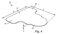
- a flat, T-shaped piece 10' is provided.
- the T-shaped piece 10' may be referred to as the protective member 10 in an unbent state.
- the T-shaped piece 10' may have been cut from a large sheet.
- the T-shaped piece 10' is typically made of a material capable of plastic deformation, for example a sheet metal.
- the T-shaped piece 10' has a head with two side portions 16' and an intermediate portion 17' which is located between the side portions 16'.
- the T-shaped piece also has a leg 18' which is joined with the head at the intermediate portion 17'.
- the leg 18', the side portions 16' and the intermediate portion 17' are all generally rectangular in the illustrated example.
- the height h' and width w' of the T-shaped piece 10' may for example be in the order of 10 cm.
- the thickness d' of the T-shaped piece 10' may for example be in the order of 1 mm.
- the side portions 16' are bent toward each other so as to form a respective angle with respect to the intermediate portion 17'.
- the angle that each side portion makes with the intermediate portion 17' is substantially 90 degrees.
- a hole 12 is provided in the leg 18'.
- the hole 12 is usually made close to the end of the leg 18' that is distal to the head.
- the leg 18' is punched so that a central zone 13 surrounding the hole 12 is pressed out of a plane of the leg 18'.
- steps S3 and S4 may occur simultaneously, i.e. the making of the hole 12 and the punching of the leg 18' can be performed in one and the same action.
- any reference signs placed between parentheses shall not be construed as limiting to the claim.
- the word “comprising” does not exclude the presence of other elements or steps than those listed in the claim.
- the word “a” or “an” preceding an element does not exclude the presence of a plurality of such elements.
Landscapes
- Engineering & Computer Science (AREA)
- Mechanical Engineering (AREA)
- Tires In General (AREA)
Priority Applications (3)
| Application Number | Priority Date | Filing Date | Title |
|---|---|---|---|
| EP16189019.9A EP3296125B1 (de) | 2016-09-15 | 2016-09-15 | Gleitschutzanordnung mit schutzelement |
| US16/333,072 US10807414B2 (en) | 2016-09-15 | 2017-09-14 | Anti-skid arrangement with protective member |
| PCT/EP2017/073134 WO2018050744A1 (en) | 2016-09-15 | 2017-09-14 | Anti-skid arrangement with protective member |
Applications Claiming Priority (1)
| Application Number | Priority Date | Filing Date | Title |
|---|---|---|---|
| EP16189019.9A EP3296125B1 (de) | 2016-09-15 | 2016-09-15 | Gleitschutzanordnung mit schutzelement |
Publications (2)
| Publication Number | Publication Date |
|---|---|
| EP3296125A1 true EP3296125A1 (de) | 2018-03-21 |
| EP3296125B1 EP3296125B1 (de) | 2019-05-15 |
Family
ID=56936364
Family Applications (1)
| Application Number | Title | Priority Date | Filing Date |
|---|---|---|---|
| EP16189019.9A Active EP3296125B1 (de) | 2016-09-15 | 2016-09-15 | Gleitschutzanordnung mit schutzelement |
Country Status (3)
| Country | Link |
|---|---|
| US (1) | US10807414B2 (de) |
| EP (1) | EP3296125B1 (de) |
| WO (1) | WO2018050744A1 (de) |
Citations (2)
| Publication number | Priority date | Publication date | Assignee | Title |
|---|---|---|---|---|
| US2543876A (en) * | 1949-04-23 | 1951-03-06 | William P C Smith | Hydraulic power unit with fixed piston for producing oscillating motion |
| SE503505C2 (sv) | 1994-10-19 | 1996-06-24 | Vbg Prod Ab | Slirskyddsanordning |
Family Cites Families (6)
| Publication number | Priority date | Publication date | Assignee | Title |
|---|---|---|---|---|
| CH642006A5 (de) * | 1978-04-10 | 1984-03-30 | Goeran Toernebaeck | Gleitschutzvorrichtung fuer fahrzeugraeder an einem kraftfahrzeug. |
| EP0195973B1 (de) * | 1985-03-14 | 1990-01-17 | Gerd Schulz Fahrzeug- und Container-Technik | Schleuderkettenaggregat für Kraftfahrzeuge |
| DE602005009002D1 (de) | 2005-12-15 | 2008-09-25 | Vbg Ab | Schwenkvorrichtung für eine Schleuderkettenanordnung eines Kraftfahrzeuges |
| US7766387B1 (en) * | 2007-08-02 | 2010-08-03 | Onspot Of North America, Inc. | Anti-skid tire chain device |
| US20110146866A1 (en) * | 2009-12-19 | 2011-06-23 | Samad Jafari Valilou | Automatic tire chain system |
| EP3296124A1 (de) * | 2016-09-15 | 2018-03-21 | VBG Group AB (Publ) | Gleitschutzanordnung für ein fahrzeug |
-
2016
- 2016-09-15 EP EP16189019.9A patent/EP3296125B1/de active Active
-
2017
- 2017-09-14 US US16/333,072 patent/US10807414B2/en active Active
- 2017-09-14 WO PCT/EP2017/073134 patent/WO2018050744A1/en not_active Ceased
Patent Citations (2)
| Publication number | Priority date | Publication date | Assignee | Title |
|---|---|---|---|---|
| US2543876A (en) * | 1949-04-23 | 1951-03-06 | William P C Smith | Hydraulic power unit with fixed piston for producing oscillating motion |
| SE503505C2 (sv) | 1994-10-19 | 1996-06-24 | Vbg Prod Ab | Slirskyddsanordning |
Non-Patent Citations (1)
| Title |
|---|
| ANONYMOUS: "Bob Johnson's Toughbook Stuff: Company Spotlight: OnSpot Automatic Tire Chains", 12 December 2011 (2011-12-12), Internet, pages 1 - 2, XP055354576, Retrieved from the Internet <URL:http://www.panasoniclaptops.com/2011/12/company-spotlight-onspot-automatic-tire.html> [retrieved on 20170314] * |
Also Published As
| Publication number | Publication date |
|---|---|
| US10807414B2 (en) | 2020-10-20 |
| EP3296125B1 (de) | 2019-05-15 |
| WO2018050744A1 (en) | 2018-03-22 |
| US20190263176A1 (en) | 2019-08-29 |
Similar Documents
| Publication | Publication Date | Title |
|---|---|---|
| JP4782146B2 (ja) | 農業車両用タイヤ | |
| KR20150103742A (ko) | 방향을 가지며 공기를 전달하도록 구성된 림, 에어레스 타이어 및 허브 캡 설계 및 이들을 이용하기 위한 방법 | |
| EP2387509A1 (de) | Zentrifugalrad | |
| WO2017193547A1 (zh) | 一种汽车爆胎应急安全装置 | |
| JP5919283B2 (ja) | 車輪を備えた車両のスリップを防止する装置 | |
| EP3296125B1 (de) | Gleitschutzanordnung mit schutzelement | |
| US6652036B2 (en) | Mud cover assembly | |
| US11007818B2 (en) | Anti-skid arrangement for a vehicle | |
| CN211222872U (zh) | 轮毂以及具有它的车轮 | |
| JP2000006622A5 (de) | ||
| JP2019064292A (ja) | 車両用ホイールディスクおよび車両用ディスクホイール | |
| US9278294B1 (en) | Tire tread attachment for use on a toy vehicle | |
| US7901012B1 (en) | Wheel which produces an eccentric visual effect | |
| CN215041845U (zh) | 一种高强度卡巴轮单胎轮毂 | |
| US6877819B1 (en) | Tire clamp substituting for spare tire | |
| JP4781544B2 (ja) | 農用車輪 | |
| US6189977B1 (en) | Go kart wheel | |
| JP6183781B2 (ja) | 乗用草刈機の操向前輪 | |
| US20160052353A1 (en) | Nonslip circular flange | |
| KR101423041B1 (ko) | 자동차바퀴 부착용 미끄럼방지장치 | |
| KR200404019Y1 (ko) | 타이어 보호를 위한 보조 디스크 구조 | |
| CN109649072B (zh) | 一种汽车轮毂的轮罩固定装置 | |
| KR0131251Y1 (ko) | 휘일 허브 캡의 장착 구조 | |
| US2270758A (en) | Tire removing tool | |
| KR101666337B1 (ko) | 차량용 미끄럼 방지패드 |
Legal Events
| Date | Code | Title | Description |
|---|---|---|---|
| PUAI | Public reference made under article 153(3) epc to a published international application that has entered the european phase |
Free format text: ORIGINAL CODE: 0009012 |
|
| STAA | Information on the status of an ep patent application or granted ep patent |
Free format text: STATUS: THE APPLICATION HAS BEEN PUBLISHED |
|
| AK | Designated contracting states |
Kind code of ref document: A1 Designated state(s): AL AT BE BG CH CY CZ DE DK EE ES FI FR GB GR HR HU IE IS IT LI LT LU LV MC MK MT NL NO PL PT RO RS SE SI SK SM TR |
|
| AX | Request for extension of the european patent |
Extension state: BA ME |
|
| STAA | Information on the status of an ep patent application or granted ep patent |
Free format text: STATUS: REQUEST FOR EXAMINATION WAS MADE |
|
| 17P | Request for examination filed |
Effective date: 20180920 |
|
| RBV | Designated contracting states (corrected) |
Designated state(s): AL AT BE BG CH CY CZ DE DK EE ES FI FR GB GR HR HU IE IS IT LI LT LU LV MC MK MT NL NO PL PT RO RS SE SI SK SM TR |
|
| GRAP | Despatch of communication of intention to grant a patent |
Free format text: ORIGINAL CODE: EPIDOSNIGR1 |
|
| STAA | Information on the status of an ep patent application or granted ep patent |
Free format text: STATUS: GRANT OF PATENT IS INTENDED |
|
| INTG | Intention to grant announced |
Effective date: 20181210 |
|
| GRAS | Grant fee paid |
Free format text: ORIGINAL CODE: EPIDOSNIGR3 |
|
| GRAA | (expected) grant |
Free format text: ORIGINAL CODE: 0009210 |
|
| STAA | Information on the status of an ep patent application or granted ep patent |
Free format text: STATUS: THE PATENT HAS BEEN GRANTED |
|
| AK | Designated contracting states |
Kind code of ref document: B1 Designated state(s): AL AT BE BG CH CY CZ DE DK EE ES FI FR GB GR HR HU IE IS IT LI LT LU LV MC MK MT NL NO PL PT RO RS SE SI SK SM TR |
|
| REG | Reference to a national code |
Ref country code: CH Ref legal event code: EP |
|
| REG | Reference to a national code |
Ref country code: DE Ref legal event code: R096 Ref document number: 602016013932 Country of ref document: DE |
|
| REG | Reference to a national code |
Ref country code: IE Ref legal event code: FG4D |
|
| REG | Reference to a national code |
Ref country code: SE Ref legal event code: TRGR |
|
| REG | Reference to a national code |
Ref country code: NL Ref legal event code: MP Effective date: 20190515 |
|
| REG | Reference to a national code |
Ref country code: LT Ref legal event code: MG4D |
|
| PG25 | Lapsed in a contracting state [announced via postgrant information from national office to epo] |
Ref country code: LT Free format text: LAPSE BECAUSE OF FAILURE TO SUBMIT A TRANSLATION OF THE DESCRIPTION OR TO PAY THE FEE WITHIN THE PRESCRIBED TIME-LIMIT Effective date: 20190515 Ref country code: NL Free format text: LAPSE BECAUSE OF FAILURE TO SUBMIT A TRANSLATION OF THE DESCRIPTION OR TO PAY THE FEE WITHIN THE PRESCRIBED TIME-LIMIT Effective date: 20190515 Ref country code: FI Free format text: LAPSE BECAUSE OF FAILURE TO SUBMIT A TRANSLATION OF THE DESCRIPTION OR TO PAY THE FEE WITHIN THE PRESCRIBED TIME-LIMIT Effective date: 20190515 Ref country code: PT Free format text: LAPSE BECAUSE OF FAILURE TO SUBMIT A TRANSLATION OF THE DESCRIPTION OR TO PAY THE FEE WITHIN THE PRESCRIBED TIME-LIMIT Effective date: 20190915 Ref country code: AL Free format text: LAPSE BECAUSE OF FAILURE TO SUBMIT A TRANSLATION OF THE DESCRIPTION OR TO PAY THE FEE WITHIN THE PRESCRIBED TIME-LIMIT Effective date: 20190515 Ref country code: ES Free format text: LAPSE BECAUSE OF FAILURE TO SUBMIT A TRANSLATION OF THE DESCRIPTION OR TO PAY THE FEE WITHIN THE PRESCRIBED TIME-LIMIT Effective date: 20190515 Ref country code: NO Free format text: LAPSE BECAUSE OF FAILURE TO SUBMIT A TRANSLATION OF THE DESCRIPTION OR TO PAY THE FEE WITHIN THE PRESCRIBED TIME-LIMIT Effective date: 20190815 Ref country code: HR Free format text: LAPSE BECAUSE OF FAILURE TO SUBMIT A TRANSLATION OF THE DESCRIPTION OR TO PAY THE FEE WITHIN THE PRESCRIBED TIME-LIMIT Effective date: 20190515 |
|
| PG25 | Lapsed in a contracting state [announced via postgrant information from national office to epo] |
Ref country code: BG Free format text: LAPSE BECAUSE OF FAILURE TO SUBMIT A TRANSLATION OF THE DESCRIPTION OR TO PAY THE FEE WITHIN THE PRESCRIBED TIME-LIMIT Effective date: 20190815 Ref country code: GR Free format text: LAPSE BECAUSE OF FAILURE TO SUBMIT A TRANSLATION OF THE DESCRIPTION OR TO PAY THE FEE WITHIN THE PRESCRIBED TIME-LIMIT Effective date: 20190816 Ref country code: LV Free format text: LAPSE BECAUSE OF FAILURE TO SUBMIT A TRANSLATION OF THE DESCRIPTION OR TO PAY THE FEE WITHIN THE PRESCRIBED TIME-LIMIT Effective date: 20190515 Ref country code: RS Free format text: LAPSE BECAUSE OF FAILURE TO SUBMIT A TRANSLATION OF THE DESCRIPTION OR TO PAY THE FEE WITHIN THE PRESCRIBED TIME-LIMIT Effective date: 20190515 |
|
| REG | Reference to a national code |
Ref country code: AT Ref legal event code: MK05 Ref document number: 1132977 Country of ref document: AT Kind code of ref document: T Effective date: 20190515 |
|
| PG25 | Lapsed in a contracting state [announced via postgrant information from national office to epo] |
Ref country code: EE Free format text: LAPSE BECAUSE OF FAILURE TO SUBMIT A TRANSLATION OF THE DESCRIPTION OR TO PAY THE FEE WITHIN THE PRESCRIBED TIME-LIMIT Effective date: 20190515 Ref country code: AT Free format text: LAPSE BECAUSE OF FAILURE TO SUBMIT A TRANSLATION OF THE DESCRIPTION OR TO PAY THE FEE WITHIN THE PRESCRIBED TIME-LIMIT Effective date: 20190515 Ref country code: DK Free format text: LAPSE BECAUSE OF FAILURE TO SUBMIT A TRANSLATION OF THE DESCRIPTION OR TO PAY THE FEE WITHIN THE PRESCRIBED TIME-LIMIT Effective date: 20190515 Ref country code: CZ Free format text: LAPSE BECAUSE OF FAILURE TO SUBMIT A TRANSLATION OF THE DESCRIPTION OR TO PAY THE FEE WITHIN THE PRESCRIBED TIME-LIMIT Effective date: 20190515 Ref country code: SK Free format text: LAPSE BECAUSE OF FAILURE TO SUBMIT A TRANSLATION OF THE DESCRIPTION OR TO PAY THE FEE WITHIN THE PRESCRIBED TIME-LIMIT Effective date: 20190515 |
|
| REG | Reference to a national code |
Ref country code: DE Ref legal event code: R097 Ref document number: 602016013932 Country of ref document: DE |
|
| PG25 | Lapsed in a contracting state [announced via postgrant information from national office to epo] |
Ref country code: IT Free format text: LAPSE BECAUSE OF FAILURE TO SUBMIT A TRANSLATION OF THE DESCRIPTION OR TO PAY THE FEE WITHIN THE PRESCRIBED TIME-LIMIT Effective date: 20190515 Ref country code: SM Free format text: LAPSE BECAUSE OF FAILURE TO SUBMIT A TRANSLATION OF THE DESCRIPTION OR TO PAY THE FEE WITHIN THE PRESCRIBED TIME-LIMIT Effective date: 20190515 |
|
| PLBE | No opposition filed within time limit |
Free format text: ORIGINAL CODE: 0009261 |
|
| STAA | Information on the status of an ep patent application or granted ep patent |
Free format text: STATUS: NO OPPOSITION FILED WITHIN TIME LIMIT |
|
| PG25 | Lapsed in a contracting state [announced via postgrant information from national office to epo] |
Ref country code: TR Free format text: LAPSE BECAUSE OF FAILURE TO SUBMIT A TRANSLATION OF THE DESCRIPTION OR TO PAY THE FEE WITHIN THE PRESCRIBED TIME-LIMIT Effective date: 20190515 |
|
| 26N | No opposition filed |
Effective date: 20200218 |
|
| PG25 | Lapsed in a contracting state [announced via postgrant information from national office to epo] |
Ref country code: PL Free format text: LAPSE BECAUSE OF FAILURE TO SUBMIT A TRANSLATION OF THE DESCRIPTION OR TO PAY THE FEE WITHIN THE PRESCRIBED TIME-LIMIT Effective date: 20190515 |
|
| PG25 | Lapsed in a contracting state [announced via postgrant information from national office to epo] |
Ref country code: MC Free format text: LAPSE BECAUSE OF FAILURE TO SUBMIT A TRANSLATION OF THE DESCRIPTION OR TO PAY THE FEE WITHIN THE PRESCRIBED TIME-LIMIT Effective date: 20190515 Ref country code: SI Free format text: LAPSE BECAUSE OF FAILURE TO SUBMIT A TRANSLATION OF THE DESCRIPTION OR TO PAY THE FEE WITHIN THE PRESCRIBED TIME-LIMIT Effective date: 20190515 |
|
| REG | Reference to a national code |
Ref country code: CH Ref legal event code: PL |
|
| PG25 | Lapsed in a contracting state [announced via postgrant information from national office to epo] |
Ref country code: LU Free format text: LAPSE BECAUSE OF NON-PAYMENT OF DUE FEES Effective date: 20190915 Ref country code: CH Free format text: LAPSE BECAUSE OF NON-PAYMENT OF DUE FEES Effective date: 20190930 Ref country code: LI Free format text: LAPSE BECAUSE OF NON-PAYMENT OF DUE FEES Effective date: 20190930 Ref country code: IE Free format text: LAPSE BECAUSE OF NON-PAYMENT OF DUE FEES Effective date: 20190915 |
|
| REG | Reference to a national code |
Ref country code: BE Ref legal event code: MM Effective date: 20190930 |
|
| PG25 | Lapsed in a contracting state [announced via postgrant information from national office to epo] |
Ref country code: BE Free format text: LAPSE BECAUSE OF NON-PAYMENT OF DUE FEES Effective date: 20190930 |
|
| PG25 | Lapsed in a contracting state [announced via postgrant information from national office to epo] |
Ref country code: FR Free format text: LAPSE BECAUSE OF NON-PAYMENT OF DUE FEES Effective date: 20190930 |
|
| PG25 | Lapsed in a contracting state [announced via postgrant information from national office to epo] |
Ref country code: RO Free format text: LAPSE BECAUSE OF FAILURE TO SUBMIT A TRANSLATION OF THE DESCRIPTION OR TO PAY THE FEE WITHIN THE PRESCRIBED TIME-LIMIT Effective date: 20190515 |
|
| GBPC | Gb: european patent ceased through non-payment of renewal fee |
Effective date: 20200915 |
|
| PG25 | Lapsed in a contracting state [announced via postgrant information from national office to epo] |
Ref country code: CY Free format text: LAPSE BECAUSE OF FAILURE TO SUBMIT A TRANSLATION OF THE DESCRIPTION OR TO PAY THE FEE WITHIN THE PRESCRIBED TIME-LIMIT Effective date: 20190515 |
|
| PG25 | Lapsed in a contracting state [announced via postgrant information from national office to epo] |
Ref country code: IS Free format text: LAPSE BECAUSE OF FAILURE TO SUBMIT A TRANSLATION OF THE DESCRIPTION OR TO PAY THE FEE WITHIN THE PRESCRIBED TIME-LIMIT Effective date: 20190915 |
|
| PG25 | Lapsed in a contracting state [announced via postgrant information from national office to epo] |
Ref country code: HU Free format text: LAPSE BECAUSE OF FAILURE TO SUBMIT A TRANSLATION OF THE DESCRIPTION OR TO PAY THE FEE WITHIN THE PRESCRIBED TIME-LIMIT; INVALID AB INITIO Effective date: 20160915 Ref country code: MT Free format text: LAPSE BECAUSE OF FAILURE TO SUBMIT A TRANSLATION OF THE DESCRIPTION OR TO PAY THE FEE WITHIN THE PRESCRIBED TIME-LIMIT Effective date: 20190515 |
|
| PG25 | Lapsed in a contracting state [announced via postgrant information from national office to epo] |
Ref country code: GB Free format text: LAPSE BECAUSE OF NON-PAYMENT OF DUE FEES Effective date: 20200915 |
|
| PG25 | Lapsed in a contracting state [announced via postgrant information from national office to epo] |
Ref country code: MK Free format text: LAPSE BECAUSE OF FAILURE TO SUBMIT A TRANSLATION OF THE DESCRIPTION OR TO PAY THE FEE WITHIN THE PRESCRIBED TIME-LIMIT Effective date: 20190515 |
|
| PGFP | Annual fee paid to national office [announced via postgrant information from national office to epo] |
Ref country code: DE Payment date: 20250806 Year of fee payment: 10 |
|
| PGFP | Annual fee paid to national office [announced via postgrant information from national office to epo] |
Ref country code: SE Payment date: 20250805 Year of fee payment: 10 |