EP3296247A1 - Détection de dispositifs de verrouillage - Google Patents
Détection de dispositifs de verrouillage Download PDFInfo
- Publication number
- EP3296247A1 EP3296247A1 EP16188778.1A EP16188778A EP3296247A1 EP 3296247 A1 EP3296247 A1 EP 3296247A1 EP 16188778 A EP16188778 A EP 16188778A EP 3296247 A1 EP3296247 A1 EP 3296247A1
- Authority
- EP
- European Patent Office
- Prior art keywords
- camera
- locking
- lock
- image processing
- processing unit
- Prior art date
- Legal status (The legal status is an assumption and is not a legal conclusion. Google has not performed a legal analysis and makes no representation as to the accuracy of the status listed.)
- Withdrawn
Links
Images

Classifications
-
- B—PERFORMING OPERATIONS; TRANSPORTING
- B66—HOISTING; LIFTING; HAULING
- B66C—CRANES; LOAD-ENGAGING ELEMENTS OR DEVICES FOR CRANES, CAPSTANS, WINCHES, OR TACKLES
- B66C13/00—Other constructional features or details
- B66C13/16—Applications of indicating, registering, or weighing devices
-
- B—PERFORMING OPERATIONS; TRANSPORTING
- B66—HOISTING; LIFTING; HAULING
- B66C—CRANES; LOAD-ENGAGING ELEMENTS OR DEVICES FOR CRANES, CAPSTANS, WINCHES, OR TACKLES
- B66C13/00—Other constructional features or details
- B66C13/18—Control systems or devices
- B66C13/46—Position indicators for suspended loads or for crane elements
-
- B—PERFORMING OPERATIONS; TRANSPORTING
- B66—HOISTING; LIFTING; HAULING
- B66C—CRANES; LOAD-ENGAGING ELEMENTS OR DEVICES FOR CRANES, CAPSTANS, WINCHES, OR TACKLES
- B66C13/00—Other constructional features or details
- B66C13/18—Control systems or devices
- B66C13/48—Automatic control of crane drives for producing a single or repeated working cycle; Program control
-
- B—PERFORMING OPERATIONS; TRANSPORTING
- B66—HOISTING; LIFTING; HAULING
- B66C—CRANES; LOAD-ENGAGING ELEMENTS OR DEVICES FOR CRANES, CAPSTANS, WINCHES, OR TACKLES
- B66C19/00—Cranes comprising trolleys or crabs running on fixed or movable bridges or gantries
- B66C19/002—Container cranes
-
- G—PHYSICS
- G05—CONTROLLING; REGULATING
- G05B—CONTROL OR REGULATING SYSTEMS IN GENERAL; FUNCTIONAL ELEMENTS OF SUCH SYSTEMS; MONITORING OR TESTING ARRANGEMENTS FOR SUCH SYSTEMS OR ELEMENTS
- G05B19/00—Program-control systems
- G05B19/02—Program-control systems electric
- G05B19/04—Program control other than numerical control, i.e. in sequence controllers or logic controllers
- G05B19/042—Program control other than numerical control, i.e. in sequence controllers or logic controllers using digital processors
- G05B19/0428—Safety, monitoring
-
- B—PERFORMING OPERATIONS; TRANSPORTING
- B66—HOISTING; LIFTING; HAULING
- B66C—CRANES; LOAD-ENGAGING ELEMENTS OR DEVICES FOR CRANES, CAPSTANS, WINCHES, OR TACKLES
- B66C19/00—Cranes comprising trolleys or crabs running on fixed or movable bridges or gantries
- B66C19/007—Cranes comprising trolleys or crabs running on fixed or movable bridges or gantries for containers
-
- G—PHYSICS
- G05—CONTROLLING; REGULATING
- G05B—CONTROL OR REGULATING SYSTEMS IN GENERAL; FUNCTIONAL ELEMENTS OF SUCH SYSTEMS; MONITORING OR TESTING ARRANGEMENTS FOR SUCH SYSTEMS OR ELEMENTS
- G05B2219/00—Program-control systems
- G05B2219/20—Pc systems
- G05B2219/24—Pc safety
- G05B2219/24097—Camera monitors controlled machine
Definitions
- the invention relates to a method for detecting locking devices on a moving object. Furthermore, the invention relates to an image processing unit, a system for carrying out a method according to the invention and an automatic loading and / or unloading system.
- Such a method is used for example in a crane system for loading containers. If a container lock is mistakenly forgotten there on the container, the container can not be further loaded without further notice. It may be caught by transport vehicles or containers. Under certain circumstances, this can lead to considerable damage to the crane mechanism, vehicles and containers, even to personal injury. If a container with a forgotten lock is turned off, it stands on the lock and it thus sets a slant of the container. So far, it is up to the crane operator to recognize such forgotten locks. In order to relieve the crane operator and to allow complete automation of such systems, a method for detecting locking devices is presented below.
- Out DE 10 2012 020 953 A1 is a method for computer-aided determination of the position in which an ISO container is to be set up by means of a crane on a host vehicle, based on a top of the host vehicle representing cloud of measuring points, which are obtained by scanning the host vehicle from above with a 3D laser scanner ,
- the measuring point cloud is scanned with at least one virtual test specimen, which at least partially has a shape which approximates the shape of the part of the carrier vehicle projecting above part of twistlocks on the carrier vehicle.
- all locations are determined at which the approximated to a twistlock form of the virtual Specimen meets at least a predetermined degree with the local shape of the measurement point cloud and from the thus set twistlock locations container target position data is calculated for the container to be placed on the carrier vehicle.
- the invention has for its object to provide a method that makes it possible to efficiently and reliably detect locking devices.
- the locking device is understood to mean both a single locking device and a plurality of locking devices. Therefore, the following is spoken of detection of locking devices or detection of a locking device, where all possible detection results are shown. Possible detection results are, for example: “no locking device was detected”, “one locking device was detected” or “several locking devices were detected”. If the method is thus carried out in order to detect only one or no locking device, then this is just as inventive as the detection of several locking devices.
- the locking devices are designed for locking a plurality of movable objects, eg freight containers, with each other and / or for locking on or with a slide and for arrangement in a Verrieglungs Symposium of the movable object.
- the movable object is designed for movement by means of a loading device and the locking area is detectable in a detection area of at least one camera.
- an image processing unit evaluates a signal from the camera for detecting locking devices in a locking area of a moving object.
- a slide may be, for example, a trailer of a truck or other carrier, which are designed to hold one or to lock with a moving object.
- the locking region of the movable object is in principle the region in which locking devices are mounted.
- these are e.g. the outer corners where the twistlocks are attached.
- one or more cameras are aligned so that the moving objects move through the detection area of the cameras during transport with the loading device and that the locking area at least partially and at least for the purpose of detecting locking devices at least temporarily in the detection area.
- the detection range is essentially based on the orientation, the resolution and the optics of the camera.
- the detection area must therefore be selected accordingly.
- the image processing unit issues an error message if a locking device has been detected.
- This error message can then be forwarded to the crane operator via the PLC, for example, which then initiates corresponding further steps.
- the PLC can also react automatically to such an error message.
- the image processing unit in the sense of increased security outputs a so-called "active high", ie a permanently active logic level. For this purpose, it is continuously signaled that no locking device has been detected. If a locking device is detected, the "active high” drops out and an error message can be output.
- the image processing unit evaluates the signal of the camera, or the signal of the cameras, to check the correct position of the movable Object off. This makes it possible to detect whether the movable object is in a position suitable for the detection of a locking device.
- the position data can be learned, for example, based on learned standardized sizes of moving objects. It is also conceivable that for each currently moving object in a central logistics system, the corresponding dimensions are deposited, which are provided to the image processing unit for checking the correct position of the moving object available. In the case of containers in particular, it makes sense to teach in or store standard dimensions in the image processing unit. It is also conceivable to deposit these standard dimensions in other memory locations which can be accessed by the image processing unit.
- the image processing unit evaluates the signal of the camera by means of a blob analysis.
- the blob analysis is a way to capture objects as so-called blobs and to distinguish them from the background in the image. It is furthermore particularly advantageous if the blob analysis takes place in the entire gray scale range in order to take into account different light influences, such as sun, shadow, rain, artificial lighting, etc. With the blob analysis, for example, the positioning and the size of the moving object can be determined and compared with a reference position / size.
- the image processing unit evaluates the signal of the camera by means of a difference image evaluation. If, for example, an unambiguous position has been determined, the evaluation of the image area below the lower container corners, in which, for example, a twistlock can be located, can be carried out by means of a differential image analysis. So there are the Verrieglungs Symposiume, which are now in the detection range of the camera or cameras by means of a differential image analysis for the presence of a locking device examined. A difference image analysis requires that the container moves (minimum pixels per movement). It is particularly advantageous that when combining the blob analysis with the difference image analysis, the system can automatically detect a change in position or movement by XY evaluation of blob analysis and thus can respond immediately to driving stops when loading without triggering false alarms.
- a controller interrupts a loading and / or unloading process when a locking device has been detected.
- the controller can be a central controller, for example in the form of a PLC, which controls the entire loading and / or unloading process.
- the control only outputs a corresponding signal to the crane operator, who then has to confirm this. The loading and / or unloading process can then be continued if the incorrectly attached locking device has been removed or the moving object, e.g. the container has been transported to a location for removing the locking device.
- the image processing unit only evaluates a signal from the camera when the movable object is in the detection area. In this way, the signals of the cameras, so the image or the images of the cameras, not permanently evaluated. This reduces unnecessary traffic through the network of the control system. If, for example, it is detected that a moving object is moving in a detection area of the camera, the detection can be carried out.
- the information as to whether a moving object is in the detection area can be supplied, for example, by a central controller which monitors the position and used for triggering or plausibility checking.
- the image processing unit is provided with classification data of the current movable object for the detection of locking devices.
- the classification data may include the type and shape of the moving object. For example, the outer dimensions of the container, u.U. even the colors as well as potential locations of locking devices are conceivable.
- the image processing unit can thus more efficiently perform the recognition of forgotten locking devices based on the classification data.
- the classification data may be provided by a controller, a central logistics system, or databases via a communication system.
- detected locking devices are automatically removed. It is conceivable that for this purpose the movable object is transported to a further location, by means of which an automatic locking device can be removed automatically or manually. It is also conceivable that a small robot e.g. in the form of one or more robotic arms or other solutions, remove the locking devices directly in the detection area. This would have the advantage that confirmation of the removal of the locking devices could be made directly by the method itself. It is conceivable that the removal is designed to be correspondingly fast in order not to interrupt the loading process, alternatively, it is also possible to interrupt the loading process at least briefly to allow a safe removal of the locking devices.
- the removal of detected locking devices is documented in a central logistics system.
- the central logistics system has information about the origin and the final whereabouts of the moving objects. Now, if the movable object is placed at another location by removing a locking device, then the central Logistic system react directly to it and a complete delivery documentation can be guaranteed.
- the image processing unit determines an identifier of the mobile object.
- the identifier can be e.g. a container number according to ISO 6346 of a container. In this way either existing data from a central logistics system can be verified and in case of doubt be updated, or a direct assignment of the unloaded goods to central logistics data can be carried out.
- an image processing unit for carrying out a method according to the invention.
- the image processing unit has at least one signal interface, a communication interface and an evaluation unit, wherein the signal interface is designed to connect at least one camera, wherein the communication interface is designed for communication with at least one controller and wherein the evaluation unit for evaluating a signal of at least a camera for detecting a Verrieglungsvorraum is formed.
- Such an image processing unit can be designed as a stand-alone unit, as part of a PLC or even cloud-based.
- the interfaces can be standard Ethernet, industry standard interfaces or other specific interfaces.
- the object is further achieved by a system for detecting locking devices on a mobile object, which has at least one image processing unit and at least one camera.
- the cameras are to be aligned so that the locking region of a movable object can be detected when moving by means of a loading device in a detection range of at least one camera.
- the at least one camera is oriented such that through the Alignment prevents sunlight during operation.
- the camera may be oriented in the direction of the direction from which no solar radiation is to be expected during operation.
- automatic cleaning systems for cleaning the camera optics to reduce optical interference are conceivable.
- the at least one camera is oriented at an inclination angle downwards, in particular at an inclination angle of 20 to 30 degrees downwards. This is particularly advantageous, as both the sun's rays and other weather conditions are minimized.
- the object is further achieved by an automatic loading and / or unloading system having at least one system for carrying out a method according to the invention, a loading device for moving a moving object and a controller for controlling a loading and / or unloading process.
- Such integration is particularly advantageous because it allows seamless integration into the logistics flow of existing equipment. The probability of failure of such a system is reduced accordingly and the availability can be increased.
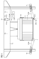
- FIG. 1 shows a loading device 100 in the form of a container crane, which is designed for loading of movable objects C, in this case in the form of containers.
- the loading device 100 has for this purpose a hoist 105, also called spreader on.
- a controller PLC is provided for controlling the loading device 100.
- the controller PLC has a communication connection COM to a communication interface PCOM of an image processing unit PU.
- the image processing unit PU further has two signal interfaces PSIG and an evaluation unit CPU.
- the communication connection COM can preferably be designed as an IP-based connection, but other protocols are also conceivable.
- the signal interfaces PSIG are designed to receive a signal SIG from cameras K1, K2.
- the cameras K1, K2 each have a detection area SCAN, which can be adjusted by their orientation.
- the cameras K1 and K2 are downwardly inclined slightly so that they can reliably detect locking devices LOCK on the underside of the moving objects C.
- locking areas L of the movable object C are located in this case, wherein a locking device LOCK is located in the right-hand locking area L and no locking device is present in the left-hand locking area L.
- the lightning-shaped arrow ERR indicates that the presence of the locking device LOCK in the right-hand locking region L is an error ERR. If the depicted movable object C, that is to say the container, would then be reloaded in this way, a slanted position of the container or, in the worst case, even a partial locking with another container would occur, which can lead to personal injury.
- the movable object C is located with its locking areas L in the detection areas SCAN.
- data coming from, for example, a central logistics system and the dimensions of a moving object C could include, used for positioning via the PLC. It is also conceivable that the image processing unit PU automatically recognizes when a lock area L is moved through the detection area SCAN.
- the cameras K1, K2 can e.g. be installed in a weatherproof housing with sunroof at an angle of about 25 ° down to minimize any impairment of the image recognition by sun and rain over a longer period of time.
- the image information that is to say the signal SIG of the cameras K1, K2, is made available to the image processing unit PU via the communication connection.
- the image processing unit PU is e.g. installed on the crane and can read the signal SIG of the cameras K1, K2, so for example, the images, digital or analog, process and pass the detection results to the controller PLC.
- the detection reliability for the detection of a locking device not removed depends on the quality of the signals SIG supplied by the cameras K1, K2. Therefore, a maintenance interval is to be considered, in which the cameras K1, K2 are cleaned. By using additional aids such as windscreen wiper system and splash water tank, maintenance can also be controlled by the PLC control.
- FIG. 2 schematically shows a possible sequence of detection of locking devices.
- moving objects C are divided into steps 1.1 to 1.4.
- the order is not binding.
- the reference numbers of the elements FIG. 1 will continue to be used.
- step 1.1 a moving object C is seen, which has a locking device LOCK, which was apparently not correctly removed.
- This moving object C will now with a loading device 100, which is not shown for clarity, loaded.
- step 1.2 a measurement or a position determination of the movable object C was carried out in this case by a blob analysis.
- the markers BL set by the blob analysis can, for example, mark the corners of a movable object C, on which in principle a locking device LOCK is to be expected.
- the detection should not work constantly.
- the unique triggering can be derived from the known coordinates of the loading device 100 or its hoist 105. In this process, it is ensured that the movable object C, ie the container, is located at least partially in the detection area SCAN of the cameras K1, K2. The detection runs during the entire process and is terminated when a certain position of the movable object 100 is reached.
- a plausibility check is carried out by means of taught-in reference positions REF. For example, this is based on constant and / or known widths of moving objects C, such as standardized container widths, which are shown here as the reference position REF. Furthermore, a plausibility position PLAUS is shown, with which, for example, an allowable deviation from the reference position REF can be indexed. For example, such an allowable deviation would be realized by means of a correspondingly large detection range SCAN of the cameras K1, K2. The detection is based on a blob analysis for the measurement or position determination of a mobile object C, as was done in step 1.2. The blob analysis can be done in the entire gray scale range to account for different light effects from sun, shade, rain, lighting emitters, etc. In step 1.3 the position determination was verified using plausibility positions PLAUS and reference positions REF.
- interlocking areas L are now determined and evaluated by a difference image evaluation.
- the left lock area L does not include a locking device
- the right lock area L erroneously contains a locking device LOCK. If the unique position has been determined according to the previous steps 1.1 to 1.3, the evaluation of the image area below the lower container corners, in which a twistlock can be located, can be carried out by means of the differential image processing.
- a difference image analysis requires that the container moves (at least one pixel per movement). The system automatically recognizes a position change / movement by X / Y evaluation of the blob analysis and can thus react to driving stops during loading without triggering false alarms.
- the detection results of the individual detection steps go through several plausibility checks related to clearly learned reference information such as distance (refers to a constant width or length of a movable object C, for example a container) and e.g. the position height, which may vary only in a minimum range.
- the training can be done once during commissioning of the system. It is conceivable that the system is calibrated regularly by means of a reference object. With additional information from the crane automation system such as: Container type 20 "/ 40" / 45 ", height normal / high / cube, different detection projects can be created to minimize the risk of interference.
- the plausibility checks can be used to detect incorrectly recognized positions caused by dirt , Weather influences, etc. discarded and thus the stability of the evaluation can be increased.
- the invention relates to a method for detecting locking devices LOCK on a movable object C, wherein the locking devices LOCK for Locking a plurality of movable objects C with each other and for arrangement in a Verrieglungs Society L of the movable object C are formed, wherein the movable object C is designed for movement by means of a loading device 100.
- the invention relates to an image processing unit PU, a system for carrying out a method according to the invention and an automatic loading and / or unloading system.
- the locking area L be detectable in a detection area SCAN of at least one camera K1, K2, and in which an image processing unit PU outputs a signal SIG of the camera K1, K2 for detecting locking devices LOCK in a locking area L a mobile object C evaluates.
Landscapes
- Engineering & Computer Science (AREA)
- Mechanical Engineering (AREA)
- Automation & Control Theory (AREA)
- Physics & Mathematics (AREA)
- General Physics & Mathematics (AREA)
- Warehouses Or Storage Devices (AREA)
- Control And Safety Of Cranes (AREA)
Priority Applications (5)
| Application Number | Priority Date | Filing Date | Title |
|---|---|---|---|
| EP16188778.1A EP3296247A1 (fr) | 2016-09-14 | 2016-09-14 | Détection de dispositifs de verrouillage |
| PCT/EP2017/070068 WO2018050365A1 (fr) | 2016-09-14 | 2017-08-08 | Détection de dispositifs de verrouillage |
| EP17752094.7A EP3475210B1 (fr) | 2016-09-14 | 2017-08-08 | Détection de dispositifs de verrouillage |
| US16/333,100 US11745987B2 (en) | 2016-09-14 | 2017-08-08 | Detection of locking devices |
| CN201780049677.6A CN109641729B (zh) | 2016-09-14 | 2017-08-08 | 锁定设备的探测 |
Applications Claiming Priority (1)
| Application Number | Priority Date | Filing Date | Title |
|---|---|---|---|
| EP16188778.1A EP3296247A1 (fr) | 2016-09-14 | 2016-09-14 | Détection de dispositifs de verrouillage |
Publications (1)
| Publication Number | Publication Date |
|---|---|
| EP3296247A1 true EP3296247A1 (fr) | 2018-03-21 |
Family
ID=57153247
Family Applications (2)
| Application Number | Title | Priority Date | Filing Date |
|---|---|---|---|
| EP16188778.1A Withdrawn EP3296247A1 (fr) | 2016-09-14 | 2016-09-14 | Détection de dispositifs de verrouillage |
| EP17752094.7A Active EP3475210B1 (fr) | 2016-09-14 | 2017-08-08 | Détection de dispositifs de verrouillage |
Family Applications After (1)
| Application Number | Title | Priority Date | Filing Date |
|---|---|---|---|
| EP17752094.7A Active EP3475210B1 (fr) | 2016-09-14 | 2017-08-08 | Détection de dispositifs de verrouillage |
Country Status (4)
| Country | Link |
|---|---|
| US (1) | US11745987B2 (fr) |
| EP (2) | EP3296247A1 (fr) |
| CN (1) | CN109641729B (fr) |
| WO (1) | WO2018050365A1 (fr) |
Cited By (5)
| Publication number | Priority date | Publication date | Assignee | Title |
|---|---|---|---|---|
| US20190367335A1 (en) * | 2016-09-14 | 2019-12-05 | Siemens Aktiengesellschaft | Detection of Locking Devices |
| CN110857186A (zh) * | 2018-08-24 | 2020-03-03 | Lase工业激光有限公司 | 用于集装箱的检查系统 |
| CN110992337A (zh) * | 2019-11-29 | 2020-04-10 | 添维信息科技(天津)有限公司 | 一种集装箱残损检测方法及系统 |
| EP3760570A1 (fr) * | 2019-07-05 | 2021-01-06 | CAMCO Technologies NV | Système desystème de balayage de récipient avec une station de lavage |
| CN114476936A (zh) * | 2022-02-28 | 2022-05-13 | 湖北三六重工有限公司 | 基于摄像投影技术的曲面异形件智能起重系统 |
Families Citing this family (4)
| Publication number | Priority date | Publication date | Assignee | Title |
|---|---|---|---|---|
| CN113135497B (zh) * | 2021-05-11 | 2024-03-26 | 上海西井科技股份有限公司 | 集卡与吊机自动对位的卸箱方法、系统、设备及存储介质 |
| KR102454058B1 (ko) * | 2022-05-17 | 2022-10-14 | 주식회사 이노메트릭스 | 크레인 안전 관리 시스템 |
| CN115849191A (zh) * | 2022-12-09 | 2023-03-28 | 武汉港迪智能技术有限公司 | 一种基于视觉的集装箱自动抓箱方法及系统 |
| DE102024126739A1 (de) * | 2024-09-17 | 2026-03-19 | Liebherr Container Cranes Ltd. | Containerbrücke |
Citations (3)
| Publication number | Priority date | Publication date | Assignee | Title |
|---|---|---|---|---|
| US6081292A (en) * | 1998-05-06 | 2000-06-27 | Mi-Jack Products, Inc. | Grappler guidance system for a gantry crane |
| DE102012020953A1 (de) | 2012-10-25 | 2014-04-30 | LASE Industrielle Lasertechnik GmbH | Verfahren zur Bestimmung der Position, in der ein ISO-Container auf ein Trägerfahrzeug aufzusetzen ist, sowie 3D-Laserscan-Messanlage dafür |
| WO2014169096A1 (fr) * | 2013-04-12 | 2014-10-16 | Dana Limited | Dispositif et procédé de commande pour verrouillage d'un container |
Family Cites Families (6)
| Publication number | Priority date | Publication date | Assignee | Title |
|---|---|---|---|---|
| JP2003054871A (ja) | 2001-08-10 | 2003-02-26 | Yuzo Shimizu | コンテナー吊用スプレッダー |
| DE10212590A1 (de) * | 2002-03-15 | 2003-10-09 | Demag Mobile Cranes Gmbh | Optische Einrichtung zur automatischen Be- und Entladung von Containern auf Fahrzeugen |
| US7922085B2 (en) * | 2007-04-13 | 2011-04-12 | Aps Technology Group, Inc. | System, method, apparatus, and computer program product for monitoring the transfer of cargo to and from a transporter |
| US7780383B2 (en) * | 2007-10-12 | 2010-08-24 | Wastequip Manufacturing Company | Locking system for roll-off containers with a positive unlocking mechanism to prevent binding |
| EP2212838A4 (fr) | 2007-11-08 | 2012-08-08 | Antonios Aikaterinidis | Appareil et procédé d'inspection indépendante d'unités de transport |
| EP3296247A1 (fr) * | 2016-09-14 | 2018-03-21 | Siemens Aktiengesellschaft | Détection de dispositifs de verrouillage |
-
2016
- 2016-09-14 EP EP16188778.1A patent/EP3296247A1/fr not_active Withdrawn
-
2017
- 2017-08-08 US US16/333,100 patent/US11745987B2/en active Active
- 2017-08-08 EP EP17752094.7A patent/EP3475210B1/fr active Active
- 2017-08-08 CN CN201780049677.6A patent/CN109641729B/zh active Active
- 2017-08-08 WO PCT/EP2017/070068 patent/WO2018050365A1/fr not_active Ceased
Patent Citations (3)
| Publication number | Priority date | Publication date | Assignee | Title |
|---|---|---|---|---|
| US6081292A (en) * | 1998-05-06 | 2000-06-27 | Mi-Jack Products, Inc. | Grappler guidance system for a gantry crane |
| DE102012020953A1 (de) | 2012-10-25 | 2014-04-30 | LASE Industrielle Lasertechnik GmbH | Verfahren zur Bestimmung der Position, in der ein ISO-Container auf ein Trägerfahrzeug aufzusetzen ist, sowie 3D-Laserscan-Messanlage dafür |
| WO2014169096A1 (fr) * | 2013-04-12 | 2014-10-16 | Dana Limited | Dispositif et procédé de commande pour verrouillage d'un container |
Non-Patent Citations (1)
| Title |
|---|
| ORLACOPRODUCTS: "View on Barge Handling", 7 May 2012 (2012-05-07), XP002765218, Retrieved from the Internet <URL:https://www.youtube.com/watch?v=sV01k5wcoOk> [retrieved on 20161214] * |
Cited By (9)
| Publication number | Priority date | Publication date | Assignee | Title |
|---|---|---|---|---|
| US20190367335A1 (en) * | 2016-09-14 | 2019-12-05 | Siemens Aktiengesellschaft | Detection of Locking Devices |
| US11745987B2 (en) * | 2016-09-14 | 2023-09-05 | Siemens Aktiengesellschaft | Detection of locking devices |
| CN110857186A (zh) * | 2018-08-24 | 2020-03-03 | Lase工业激光有限公司 | 用于集装箱的检查系统 |
| EP3760570A1 (fr) * | 2019-07-05 | 2021-01-06 | CAMCO Technologies NV | Système desystème de balayage de récipient avec une station de lavage |
| WO2021004668A1 (fr) * | 2019-07-05 | 2021-01-14 | Camco Technologies Nv | Système de balayage de conteneur avec station de lavage |
| CN114040887A (zh) * | 2019-07-05 | 2022-02-11 | 凯姆科技术股份有限公司 | 带有清洗站的集装箱扫描系统 |
| US12155934B2 (en) | 2019-07-05 | 2024-11-26 | Camco Technologies Nv | Container scanning system with washing station |
| CN110992337A (zh) * | 2019-11-29 | 2020-04-10 | 添维信息科技(天津)有限公司 | 一种集装箱残损检测方法及系统 |
| CN114476936A (zh) * | 2022-02-28 | 2022-05-13 | 湖北三六重工有限公司 | 基于摄像投影技术的曲面异形件智能起重系统 |
Also Published As
| Publication number | Publication date |
|---|---|
| WO2018050365A1 (fr) | 2018-03-22 |
| US20190367335A1 (en) | 2019-12-05 |
| US11745987B2 (en) | 2023-09-05 |
| CN109641729B (zh) | 2020-10-13 |
| CN109641729A (zh) | 2019-04-16 |
| EP3475210A1 (fr) | 2019-05-01 |
| EP3475210B1 (fr) | 2020-07-15 |
Similar Documents
| Publication | Publication Date | Title |
|---|---|---|
| EP3475210B1 (fr) | Détection de dispositifs de verrouillage | |
| EP3000762B1 (fr) | Procédé de détermination optique, automatique d'une position cible pour un palonnier de conteneur | |
| EP2574587B1 (fr) | Procédé de détermination d'une position cible pour un palonnier de conteneur et le palonnier de conteneur | |
| DE10251910B4 (de) | Containerkran | |
| DE112013000938B4 (de) | System und verfahren zum materialtransport mit einem oder mehreren bildgebungsgeräten | |
| EP3587220A1 (fr) | Véhicule comprenant un système de man uvre | |
| EP3750842B1 (fr) | Chargement d'une charge à l'aide d'un système de grue | |
| DE102004028763A1 (de) | Andockassistent | |
| EP3597490B1 (fr) | Procédé de surveillance de l'état de chargement des véhicules utilitaires ou caisses mobiles pour véhicules utilitaires | |
| WO2020001963A1 (fr) | Procédé et système permettant de déterminer une pose relative entre un objet cible et un véhicule | |
| EP2107336B1 (fr) | Procédé et dispositif de reconnaissance d'image d'objets mobiles, comme par exemple dans des installations de transport | |
| WO1996007929A1 (fr) | Agencement pour la detection automatique de la position d'un vehicule de transport de conteneurs | |
| DE102019101415A1 (de) | Fahrunterstützungsverfahren | |
| DE19959623C2 (de) | Verfahren und Anordnung zum Lokalisieren von zylinderförmigen Objekten | |
| DE102018210361B4 (de) | Verfahren zum Ermitteln einer Relativpose zwischen einem Fahrzeug und einem Zielobjekt | |
| DE202022103063U1 (de) | Vorrichtung zum Ermitteln der räumlichen Lage von Aufnahmeelementen eines Containers | |
| DE102022106769A1 (de) | Verfahren zur Zustandskontrolle wenigstens zweier Bereiche eines Objekts | |
| EP3103757A1 (fr) | Procédé et système de détection d'un levage d'un véhicule porte-conteneur | |
| DE102020122030A1 (de) | Intralogistisches System | |
| EP4620889B1 (fr) | Surveillance de zone dans une grue intermodale | |
| DE102012018850A1 (de) | Verfahren und Vorrichtung zur Verfolgung von Containern, die unter Zuhilfenahme einer Zugmaschine in einem Hafentermial transportiert werden | |
| DE102025107974A1 (de) | Messsystem, messverfahren und computerlesbares speichermedium | |
| EP3466848A1 (fr) | Dispositif et procédé de vérification d'un processus de palettisation | |
| EP4286790A1 (fr) | Dispositif et procédé de détermination de la position spatiale des éléments de réception d'un conteneur | |
| DE102023208956A1 (de) | Verfahren zur Objekterkennung in einer Umgebung |
Legal Events
| Date | Code | Title | Description |
|---|---|---|---|
| PUAI | Public reference made under article 153(3) epc to a published international application that has entered the european phase |
Free format text: ORIGINAL CODE: 0009012 |
|
| AK | Designated contracting states |
Kind code of ref document: A1 Designated state(s): AL AT BE BG CH CY CZ DE DK EE ES FI FR GB GR HR HU IE IS IT LI LT LU LV MC MK MT NL NO PL PT RO RS SE SI SK SM TR |
|
| AX | Request for extension of the european patent |
Extension state: BA ME |
|
| STAA | Information on the status of an ep patent application or granted ep patent |
Free format text: STATUS: THE APPLICATION IS DEEMED TO BE WITHDRAWN |
|
| 18D | Application deemed to be withdrawn |
Effective date: 20180922 |