EP3296421A1 - Flux de vapeur en colonne ebpvd - Google Patents
Flux de vapeur en colonne ebpvd Download PDFInfo
- Publication number
- EP3296421A1 EP3296421A1 EP17191080.5A EP17191080A EP3296421A1 EP 3296421 A1 EP3296421 A1 EP 3296421A1 EP 17191080 A EP17191080 A EP 17191080A EP 3296421 A1 EP3296421 A1 EP 3296421A1
- Authority
- EP
- European Patent Office
- Prior art keywords
- gas
- crucible
- vapor
- coating
- vapor deposition
- Prior art date
- Legal status (The legal status is an assumption and is not a legal conclusion. Google has not performed a legal analysis and makes no representation as to the accuracy of the status listed.)
- Granted
Links
Images



Classifications
-
- C—CHEMISTRY; METALLURGY
- C23—COATING METALLIC MATERIAL; COATING MATERIAL WITH METALLIC MATERIAL; CHEMICAL SURFACE TREATMENT; DIFFUSION TREATMENT OF METALLIC MATERIAL; COATING BY VACUUM EVAPORATION, BY SPUTTERING, BY ION IMPLANTATION OR BY CHEMICAL VAPOUR DEPOSITION, IN GENERAL; INHIBITING CORROSION OF METALLIC MATERIAL OR INCRUSTATION IN GENERAL
- C23C—COATING METALLIC MATERIAL; COATING MATERIAL WITH METALLIC MATERIAL; SURFACE TREATMENT OF METALLIC MATERIAL BY DIFFUSION INTO THE SURFACE, BY CHEMICAL CONVERSION OR SUBSTITUTION; COATING BY VACUUM EVAPORATION, BY SPUTTERING, BY ION IMPLANTATION OR BY CHEMICAL VAPOUR DEPOSITION, IN GENERAL
- C23C14/00—Coating by vacuum evaporation, by sputtering or by ion implantation of the coating forming material
- C23C14/22—Coating by vacuum evaporation, by sputtering or by ion implantation of the coating forming material characterised by the process of coating
- C23C14/24—Vacuum evaporation
- C23C14/28—Vacuum evaporation by wave energy or particle radiation
- C23C14/30—Vacuum evaporation by wave energy or particle radiation by electron bombardment
-
- C—CHEMISTRY; METALLURGY
- C23—COATING METALLIC MATERIAL; COATING MATERIAL WITH METALLIC MATERIAL; CHEMICAL SURFACE TREATMENT; DIFFUSION TREATMENT OF METALLIC MATERIAL; COATING BY VACUUM EVAPORATION, BY SPUTTERING, BY ION IMPLANTATION OR BY CHEMICAL VAPOUR DEPOSITION, IN GENERAL; INHIBITING CORROSION OF METALLIC MATERIAL OR INCRUSTATION IN GENERAL
- C23C—COATING METALLIC MATERIAL; COATING MATERIAL WITH METALLIC MATERIAL; SURFACE TREATMENT OF METALLIC MATERIAL BY DIFFUSION INTO THE SURFACE, BY CHEMICAL CONVERSION OR SUBSTITUTION; COATING BY VACUUM EVAPORATION, BY SPUTTERING, BY ION IMPLANTATION OR BY CHEMICAL VAPOUR DEPOSITION, IN GENERAL
- C23C14/00—Coating by vacuum evaporation, by sputtering or by ion implantation of the coating forming material
- C23C14/22—Coating by vacuum evaporation, by sputtering or by ion implantation of the coating forming material characterised by the process of coating
- C23C14/228—Gas flow assisted PVD deposition
-
- C—CHEMISTRY; METALLURGY
- C23—COATING METALLIC MATERIAL; COATING MATERIAL WITH METALLIC MATERIAL; CHEMICAL SURFACE TREATMENT; DIFFUSION TREATMENT OF METALLIC MATERIAL; COATING BY VACUUM EVAPORATION, BY SPUTTERING, BY ION IMPLANTATION OR BY CHEMICAL VAPOUR DEPOSITION, IN GENERAL; INHIBITING CORROSION OF METALLIC MATERIAL OR INCRUSTATION IN GENERAL
- C23C—COATING METALLIC MATERIAL; COATING MATERIAL WITH METALLIC MATERIAL; SURFACE TREATMENT OF METALLIC MATERIAL BY DIFFUSION INTO THE SURFACE, BY CHEMICAL CONVERSION OR SUBSTITUTION; COATING BY VACUUM EVAPORATION, BY SPUTTERING, BY ION IMPLANTATION OR BY CHEMICAL VAPOUR DEPOSITION, IN GENERAL
- C23C14/00—Coating by vacuum evaporation, by sputtering or by ion implantation of the coating forming material
- C23C14/22—Coating by vacuum evaporation, by sputtering or by ion implantation of the coating forming material characterised by the process of coating
- C23C14/24—Vacuum evaporation
- C23C14/243—Crucibles for source material
-
- C—CHEMISTRY; METALLURGY
- C23—COATING METALLIC MATERIAL; COATING MATERIAL WITH METALLIC MATERIAL; CHEMICAL SURFACE TREATMENT; DIFFUSION TREATMENT OF METALLIC MATERIAL; COATING BY VACUUM EVAPORATION, BY SPUTTERING, BY ION IMPLANTATION OR BY CHEMICAL VAPOUR DEPOSITION, IN GENERAL; INHIBITING CORROSION OF METALLIC MATERIAL OR INCRUSTATION IN GENERAL
- C23C—COATING METALLIC MATERIAL; COATING MATERIAL WITH METALLIC MATERIAL; SURFACE TREATMENT OF METALLIC MATERIAL BY DIFFUSION INTO THE SURFACE, BY CHEMICAL CONVERSION OR SUBSTITUTION; COATING BY VACUUM EVAPORATION, BY SPUTTERING, BY ION IMPLANTATION OR BY CHEMICAL VAPOUR DEPOSITION, IN GENERAL
- C23C14/00—Coating by vacuum evaporation, by sputtering or by ion implantation of the coating forming material
- C23C14/22—Coating by vacuum evaporation, by sputtering or by ion implantation of the coating forming material characterised by the process of coating
- C23C14/54—Controlling or regulating the coating process
- C23C14/542—Controlling the film thickness or evaporation rate
- C23C14/543—Controlling the film thickness or evaporation rate using measurement on the vapor source
-
- H—ELECTRICITY
- H01—ELECTRIC ELEMENTS
- H01J—ELECTRIC DISCHARGE TUBES OR DISCHARGE LAMPS
- H01J37/00—Discharge tubes with provision for introducing objects or material to be exposed to the discharge, e.g. for the purpose of examination or processing thereof
- H01J37/30—Electron-beam or ion-beam tubes for localised treatment of objects
- H01J37/305—Electron-beam or ion-beam tubes for localised treatment of objects for casting, melting, evaporating, or etching
- H01J37/3053—Electron-beam or ion-beam tubes for localised treatment of objects for casting, melting, evaporating, or etching for evaporating or etching
Definitions
- This disclosure relates to an electron beam vapor deposition apparatus and method for depositing coatings with desirable microstructural morphology and orientations on work pieces, and with improved thickness uniformity.
- Electron beam vapor deposition devices are known and used for depositing coatings, such as ceramic coatings, onto work pieces.
- coatings such as ceramic coatings
- airfoils for use in turbine engines may include ceramic coatings to protect an underlying metallic alloy from oxidation and corrosion during engine operation.
- the columnar structure increases the durability of the coating.
- available deposition processes are not practically economic or are incapable of depositing a suitable coating with the desired morphology, orientation, and thickness uniformity on all surfaces of a work piece.
- E-PVD electron beam physical vapor deposition
- the temperatures of the underlying base alloy during coating required to ensure desirable columnar coating morphology are undesirably high, e.g., 2050 degrees F (1120°C). Since the strength of the underlying base alloys are degraded by high temperature exposures, this results in an undesirably narrow processing window for the coating process. Increasing the energy state of the depositing molecules reduces the required temperature of the underlying base alloy during coating.
- the beam power density delivered to the melt pool there is an upper limit to the beam power density delivered to the melt pool. Excessive beam power density can result in plasma formation in the coating chamber or in the electron beam guns.
- the plasma robs power from the beam, which can reduce power delivered into the melt pool.
- the pool may reduce temperature and may even freeze. When this happens, the cycle can start again resulting in a fluctuating process.
- the energy state of the vapor formed from the melt pool under these fluctuating conditions varies significantly, resulting in poor morphology of the coating, for some coating compositions.
- the vapor ions in the EB gun can cause plasma discharges and increased temperature inside the gun. What is needed is to enlarge the process parameter window while improving the process stability to improve the coating structure.
- an electron beam vapor deposition process for depositing coatings comprising placing a source coating material in a crucible of a vapor deposition apparatus; energizing the source coating with an electron beam raster pattern that delivers a controlled power density to the material in the crucible forming a vapor cloud from the source coating material; and depositing the source coating material onto a surface of a work piece.
- the controlled power density ranges from about 800 to about 1500 W/cm 2 .
- the controlled power density comprises about 1400 W/cm 2 .
- the controlled power density comprises about 1100 W/cm 2 .
- the process further comprises columnating the vapor cloud to reduce a volume of the vapor cloud.
- the forming step further comprises directing a process gas through a predetermined pattern of gas jets surrounding the low pressure vapor cloud.
- the process further comprises propelling the process gas from the gas jets at a sub-sonic velocity.
- a vapor deposition system comprising a coating chamber having a crucible; a source coating material located in the crucible; an electron beam source configured to direct an electron beam raster pattern with controlled power density onto the source coating material; a work piece located in the coating chamber; wherein the low energy electron beam creates a vapor cloud to form a columnar coating on the work piece in the absence of plasma discharge in the coating chamber and/or electron beam source.
- the controlled power density ranges from about 800 to about 1500 W/cm 2 .
- the controlled power density comprises about 1400 W/cm 2 .
- the vapor deposition system further comprises a predetermined pattern of gas jets formed in the crucible configured to propel a process gas that surrounds the vapor cloud forming a columnar shape.
- the vapor deposition system further comprises a predetermined pattern of gas jets formed in a manifold surrounding the crucible configured to propel a process gas that surrounds the vapor cloud forming a columnar shape.
- the gas jets discharge the process gas at a sub-sonic velocity.
- the gas jets discharge the process gas at a sub-sonic velocity.
- the vapor deposition system further comprises a gas manifold formed in the crucible configured to supply the gas jets with the process gas and oriented so as to provide additional energy to the vapor cloud, enabling columnar coating structures at lower temperatures, pressures, and pool power density.
- the vapor deposition system further comprises a gas manifold formed in the coating chamber distally from the crucible configured to supply the gas jets with the process gas and oriented so as to provide additional energy to the vapor cloud, enabling columnar coating structures at lower temperatures, pressures, and pool power density.
- Figures 1 and 6 illustrate selected portions of an example electron beam vapor deposition apparatus 10 (hereafter "the deposition apparatus 10") for coating a work piece 12 (or work pieces 12), such as airfoils or paired turbine vanes of a gas turbine engine.
- the work piece 12 may include surfaces that are difficult to coat with a desired coating thickness and/or microstructural orientation due to the geometry of the work piece 12. That is, the work piece 12 may have angled or curved surfaces and/or surfaces having low exposure relative to another surface.
- turbine vane segments for example, which have angled fillet surfaces with the platform and airfoils with a relatively small gap therebetween.
- the exemplary deposition apparatus 10 is not limited to use for any particular type of work piece 12.
- the type of coating deposited onto the work piece 12 may be any coating that is suitable for vapor deposition, such as metallic coatings or ceramic coatings.
- the coating may be a ceramic thermal barrier coating that includes gadolinia, zirconia, yttria, or combinations thereof.
- the deposition apparatus 10 includes a coating chamber 14 for containing the work pieces 12 during a coating operation and establishing desirable coating conditions.
- the coating chamber 14 may be a vacuum chamber and may include various ports for evacuating the interior or for selectively introducing process gases.
- a gas source 16 may provide a desired flow of oxygen or other process gas into the coating chamber 14.
- a pump 18 may circulate a coolant (e.g., water) through walls of the coating chamber 14 to control wall temperature.
- a coolant e.g., water
- At least one electron beam source 20 such as an electron gun, is mounted relative to the coating chamber 14 for melting and evaporating a source coating material 34, such as an ingot.
- a source coating material 34 such as an ingot.
- two electron beam sources 20 are shown; however, the deposition apparatus 10 may alternatively include a single electron beam source 20 or more than two electron beam sources 20. Given this description, one of ordinary skill in the art will recognize an appropriate number of the electron beam sources 20 to meet their particular needs.
- a transport 22 is configured to hold and move the work piece 12 back and forth in direction 24 to move the work piece 12 in and out of the coating chamber 14 and in and out of a coating zone 26 where the work piece 12 is to be coated.
- the coating zone 26 may be the spatial volume in the coating chamber 14 where the work piece 12 is coated.
- the transport 22 includes a shaft 28 that may be adapted to receive one or more fixtures that hold one or more of the work pieces 12. The shaft 28 may be translated in a known manner using a motor, actuator, or the like.
- a coating device 30 is located near the coating zone 26, such as below the coating zone 26, and includes at least one crucible 32 for presenting at least one source coating material 34 that is to be deposited onto the work piece 12.
- the coating device 30 may include a single crucible that is used for different deposition modes of the deposition apparatus 10.
- a desirable stand-off distance may be established between the coating device 30 and the coating zone 26 and/or work piece 12, depending on the geometry of the work piece 12, settings of the electron beam source(s) 20, and other factors.
- the deposition apparatus 10 may also include a thermal hood (not shown) arranged near the coating zone 26 to facilitate temperature control.
- a thermal hood is disclosed in application co-pending and commonly-owned Ser. No. 12/196,368 entitled “DEPOSITION APPARATUS HAVING THERMAL HOOD”.
- a controller 36 is in communication with the transport 22 and, optionally, the electron beam source 20 and possibly other components of the deposition apparatus 10 to control the operation thereof.
- the controller 36 may include software, hardware, or both for operating the deposition apparatus 10.
- the controller 36 may be configured to control movement of the work piece 12 in and out of the coating chamber 14 into the coating zone 26 and movement of the work piece 12 within the coating zone 26 during a coating operation.
- a deposition gas source(s) 38 is coupled to the crucible 32 and provides deposition gas.
- FIG. 2 graph that approximates temperature and pressure effects on Gadolinia Stabilized Zirconia (GSZ) and Yttria Stabilized Zirconia (YSZ) microstructures at a certain vapor energy state.
- GSZ Gadolinia Stabilized Zirconia
- YSZ Yttria Stabilized Zirconia
- the upper curve is GSZ and the lower curve is YSZ.
- the curves converge at around 0.3 Pascal pressure, and diverge as pressure is increased.
- the resulting GSZ and YSZ coating microstructures change from a columnar structure to feathered columns on either side of their respective curve.
- the parameters in the area above both curves produce columnar structures on both species. Below both curves feathered structures are generated. Between the curves columnar YSZ and feathered GSZ are produced.
- the structure changes are hypothesized to be related to molecular volume of each material and vapor particle energy.
- the process parameter window can be enlarged to avoid plasma generation to stabilize the process to improve the coating structure by decreasing the power density in the source coating material melt pool.
- the power density in the pool can be decreased from about 2600 W/cm 2 to as low as 800 W/cm 2 .
- the energy in the pool can be decreased from about 2600 W/cm 2 to about 1400 W/cm 2 .
- the energy can be decreased from approximately 2600 W/cm 2 to about 1100 W/cm 2 .
- the pressure during the coating process can be controlled to improve the coating structure.
- the pressure can be reduced from 6 Pa to about 3 Pa.
- gas jets 40 can be incorporated into the crucible 32.
- the gas jets 40 distribute a sub-sonic jet of process gas 38.
- the process gas 38 propelled from the gas jets 40 shape the vapor cloud 42 and direct the vapor cloud 42 toward the work piece 12. This is because the orientation of the gas jets 40 is in the direction of the workpiece 12.
- collisions between process gas molecules and vapor molecules increase the velocity of the vapor molecules in the direction of the workpiece 12.
- the sub-sonic jet of process gas 38 reduces the adverse effects of the vapor cloud 42 on the electron beam gun 20 and has less of an impact on the coating thickness distribution on coated surfaces, as compared to the use of super-sonic jets.
- FIG. 4 shows an exemplary low vacuum operation vapor cloud 42 columnated by the injected gas 38.
- the oriented process gas reduces the expansion of the vapor cloud above the melt pool. This reduces the volume of the vapor cloud, increasing the partial pressure of the vapor in the vapor cloud.
- Figures 5 and 6 show the exemplary crucible 32 equipped with the gas jets 40 and a gas manifold 46 supplying the process gas 38 to the gas jets 40.
- a beam pattern 48 from the electron beam 50 can be seen as larger in diameter than the source coating material ingot 34.
- the beam pattern 48 has a diameter less than the diameter of the crucible 32.
- the manifold 46 with gas jets 40 can have a diameter of 160% larger than the beam pattern 48 or source coating material ingot 34 to avoid interaction of the beam pattern with the process gas and to avoid coating of the manifold by inadvertent overflow of the melt pool, which occurs commonly.
- FIG. 7 shows a liquid cooled crucible 32 with liquid cooling channels 44.
- the crucible 32 includes the gas manifold 46 that supplies the individual gas jets 40.
- the gas jets 40 are arranged coaxially in a pattern 52 to ensure uniform interaction with the vapor cloud, to columnate the vapor cloud.
- the diameter of the orifices in the gas manifold are sized to avoid clogging by inadvertent overflow of the melt pool or backscattered deposition. Since the process gas velocity is subsonic, the orifice size is not critical. Typical process gas flowrates range from 1 to 10 slpm, preferably 3 to 6 slpm.
- Process gas compositions include oxygen, argon, and helium, or mixtures of these gases.
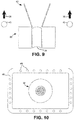
- Figures 9 to 11 show an alternate embodiment of the process gas manifold 46.
- the process gas manifold 46 is located away from the crucible 32.
- the process gas jets 40 are still oriented in the direction of the workpiece 12.
- This embodiment has the advantage of not needing to be cooled to avoid damage to the gas manifold by the electron beam pattern and the high heat of the deposition process. This embodiment also avoids problems due to inadvertent overflow of the melt pool.
- Figure 12 shows another embodiment of the gas manifolds shown in Figures 5, 8 , and 10 .
- a tube 58 is welded to the process gas manifold 38 such as a longitudinal axis 60 of the tube is coaxial with an orifice 62 that is drilled in the process gas manifold 38.
- the diameter of the tube 58 is at least 2X the diameter of the orifice 62, and the length of the tube 58 is at least 5X the diameter of the tube 58.
- These tubes 58 prevent clogging of the orifices 62 by backscattered vapor molecules or inadvertent overflow of the melt pool.
- gas jets 40 provide additional energy to the vapor molecules, enabling columnar coating microstructures at lower temperatures, pressures, and pool power density.
- the gas jet streams 40 reduce the cycle time of the process to meet a target thickness distribution on the parts.
- the gas jet streams may also improve coating thickness uniformity on complex-shaped parts such as vane clusters.
- the advantages of the exemplary deposition apparatus is that by reducing the power density in the melt pool of the source coating material, process fluctuation is avoided, which promotes the formation of desirable columnar coating microstructures.
Landscapes
- Chemical & Material Sciences (AREA)
- Engineering & Computer Science (AREA)
- Organic Chemistry (AREA)
- Materials Engineering (AREA)
- Mechanical Engineering (AREA)
- Metallurgy (AREA)
- Chemical Kinetics & Catalysis (AREA)
- Health & Medical Sciences (AREA)
- Toxicology (AREA)
- Physics & Mathematics (AREA)
- Plasma & Fusion (AREA)
- Analytical Chemistry (AREA)
- Physical Vapour Deposition (AREA)
Applications Claiming Priority (1)
| Application Number | Priority Date | Filing Date | Title |
|---|---|---|---|
| US15/265,102 US10724133B2 (en) | 2016-09-14 | 2016-09-14 | EBPVD columnated vapor stream |
Publications (2)
| Publication Number | Publication Date |
|---|---|
| EP3296421A1 true EP3296421A1 (fr) | 2018-03-21 |
| EP3296421B1 EP3296421B1 (fr) | 2021-12-29 |
Family
ID=59858979
Family Applications (1)
| Application Number | Title | Priority Date | Filing Date |
|---|---|---|---|
| EP17191080.5A Active EP3296421B1 (fr) | 2016-09-14 | 2017-09-14 | Flux de vapeur en colonne ebpvd |
Country Status (2)
| Country | Link |
|---|---|
| US (1) | US10724133B2 (fr) |
| EP (1) | EP3296421B1 (fr) |
Cited By (1)
| Publication number | Priority date | Publication date | Assignee | Title |
|---|---|---|---|---|
| EP3719168A1 (fr) * | 2019-04-05 | 2020-10-07 | Raytheon Technologies Corporation | Procédé et appareil de dépôt en phase vapeur par faisceau d'électrons |
Citations (3)
| Publication number | Priority date | Publication date | Assignee | Title |
|---|---|---|---|---|
| US20030207031A1 (en) * | 2002-05-06 | 2003-11-06 | Honeywell International, Inc. | Methods to make nanolaminate thermal barrier coatings |
| EP2261387A1 (fr) * | 2009-03-31 | 2010-12-15 | United Technologies Corporation | Appareil de dépôt en phase vapeur par faisceau d'électrons pour le dépôt d'un revêtement multicouche |
| US20120137974A1 (en) * | 2001-09-10 | 2012-06-07 | University Of Virginia Patent Foundation | Method and Apparatus For Application of Metallic Alloy Coatings |
Family Cites Families (25)
| Publication number | Priority date | Publication date | Assignee | Title |
|---|---|---|---|---|
| DE1766384B1 (de) * | 1968-05-11 | 1970-07-16 | Agfa Gevaert Ag | Drehspulmesswerk |
| US3620815A (en) | 1969-03-13 | 1971-11-16 | United Aircraft Corp | Vapor collimation in vacuum deposition of coatings |
| DE4235199C1 (fr) * | 1992-10-19 | 1993-04-22 | Fraunhofer-Gesellschaft Zur Foerderung Der Angewandten Forschung Ev, 8000 Muenchen, De | |
| US5534314A (en) * | 1994-08-31 | 1996-07-09 | University Of Virginia Patent Foundation | Directed vapor deposition of electron beam evaporant |
| US5736073A (en) * | 1996-07-08 | 1998-04-07 | University Of Virginia Patent Foundation | Production of nanometer particles by directed vapor deposition of electron beam evaporant |
| AU2003225170A1 (en) * | 2002-04-25 | 2003-11-10 | University Of Virginia Patent Foundation | Apparatus and method for high rate uniform coating, including non-line of sight |
| WO2004011688A2 (fr) * | 2002-07-25 | 2004-02-05 | University Of Virginia Patent Foundation | Procede et appareil de dispersion de revetements de liaison renforces pour revetements barrieres thermiques |
| US8110043B2 (en) * | 2004-01-08 | 2012-02-07 | University Of Virginia Patent Foundation | Apparatus and method for applying coatings onto the interior surfaces of components and related structures produced therefrom |
| US8084086B2 (en) * | 2005-06-30 | 2011-12-27 | University Of Virginia Patent Foundation | Reliant thermal barrier coating system and related methods and apparatus of making the same |
| US20070141233A1 (en) * | 2005-12-21 | 2007-06-21 | United Technologies Corporation | EB-PVD system with automatic melt pool height control |
| US20100263590A1 (en) * | 2008-12-01 | 2010-10-21 | United Technologies Corporation | Vapor Deposition Electron Beam Current Control |
| PL2401232T3 (pl) * | 2009-02-24 | 2016-10-31 | Bezpośrednie napylanie próżniowe wspomagane plazmą z współosiowej drążonej katody i związany z nim sposób | |
| US8419857B2 (en) | 2009-03-31 | 2013-04-16 | United Technologies Corporation | Electron beam vapor deposition apparatus and method of coating |
| WO2013106006A1 (fr) * | 2011-03-15 | 2013-07-18 | Directed Vapor Technologies International | Procédé d'application de revêtements en alliage d'aluminium pour la protection de l'acier contre la corrosion |
| US8541069B2 (en) | 2011-04-11 | 2013-09-24 | United Technologies Corporation | Method of guided non-line of sight coating |
| US8951350B2 (en) * | 2011-05-03 | 2015-02-10 | United Technologies Corporation | Coating methods and apparatus |
| WO2013085625A2 (fr) * | 2011-10-17 | 2013-06-13 | Directed Vapor Technologies International | Revêtements de barrière thermique et environnementale résistant à l'érosion et aux chocs |
| US20130142942A1 (en) * | 2011-11-17 | 2013-06-06 | Abbott Diabetes Care Inc. | Methods of Making a Reference Electrode for an Electrochemical Sensor |
| US20130236659A1 (en) * | 2012-03-07 | 2013-09-12 | Honeywell International Inc. | Methods for vapor depositing high temperature coatings on gas turbine engine components utilizing pre-alloyed pucks |
| WO2013188516A1 (fr) * | 2012-06-12 | 2013-12-19 | Directed Vapor Technologies International, Inc. | Revêtement autoréparant formant barrière environnementale |
| EP4379087A3 (fr) * | 2013-03-15 | 2024-09-11 | RTX Corporation | Appareil et procédés de dépôt |
| US10233533B2 (en) * | 2014-01-09 | 2019-03-19 | United Technologies Corporation | Coating process using gas screen |
| US10889895B2 (en) * | 2014-06-12 | 2021-01-12 | Raytheon Technologies Corporation | Deposition apparatus and use methods |
| US10106882B2 (en) * | 2015-10-12 | 2018-10-23 | United Technologies Corporation | Method of forming a multi-layered coating with columnar microstructure and branched columnar microstructure |
| US10851452B2 (en) * | 2016-09-14 | 2020-12-01 | Directed Vapor Technologies International, Inc. | Methods for evaporating and depositing high vapor pressure materials |
-
2016
- 2016-09-14 US US15/265,102 patent/US10724133B2/en active Active
-
2017
- 2017-09-14 EP EP17191080.5A patent/EP3296421B1/fr active Active
Patent Citations (3)
| Publication number | Priority date | Publication date | Assignee | Title |
|---|---|---|---|---|
| US20120137974A1 (en) * | 2001-09-10 | 2012-06-07 | University Of Virginia Patent Foundation | Method and Apparatus For Application of Metallic Alloy Coatings |
| US20030207031A1 (en) * | 2002-05-06 | 2003-11-06 | Honeywell International, Inc. | Methods to make nanolaminate thermal barrier coatings |
| EP2261387A1 (fr) * | 2009-03-31 | 2010-12-15 | United Technologies Corporation | Appareil de dépôt en phase vapeur par faisceau d'électrons pour le dépôt d'un revêtement multicouche |
Cited By (1)
| Publication number | Priority date | Publication date | Assignee | Title |
|---|---|---|---|---|
| EP3719168A1 (fr) * | 2019-04-05 | 2020-10-07 | Raytheon Technologies Corporation | Procédé et appareil de dépôt en phase vapeur par faisceau d'électrons |
Also Published As
| Publication number | Publication date |
|---|---|
| US10724133B2 (en) | 2020-07-28 |
| EP3296421B1 (fr) | 2021-12-29 |
| US20180073129A1 (en) | 2018-03-15 |
Similar Documents
| Publication | Publication Date | Title |
|---|---|---|
| US11725269B2 (en) | Deposition apparatus and methods | |
| US7879411B2 (en) | Method and apparatus for efficient application of substrate coating | |
| US8084086B2 (en) | Reliant thermal barrier coating system and related methods and apparatus of making the same | |
| EP2401232B1 (fr) | Dépôt en phase vapeur dirigé assisté d'un plasma à cathode creuse coaxial, et procédé associé | |
| EP2261387B1 (fr) | Appareil de dépôt en phase vapeur par faisceau d'électrons pour le dépôt d'un revêtement multicouche | |
| EP2213762B1 (fr) | Dispositif de revêtement et appareil de dépôt | |
| JP2012082519A (ja) | 熱遮蔽被覆構造体を製造する方法 | |
| EP2468918A2 (fr) | Appareil de dépôt de revêtement et procédé correspondant | |
| US8419857B2 (en) | Electron beam vapor deposition apparatus and method of coating | |
| EP3296421B1 (fr) | Flux de vapeur en colonne ebpvd | |
| US11866816B2 (en) | Apparatus for use in coating process | |
| EP3092324B1 (fr) | Procédé de revêtement utilisant un écran de gaz | |
| US20160040284A1 (en) | Pressure modulated coating | |
| US20190368033A1 (en) | Selective vapor deposition process for additive manufacturing | |
| EP4249627A1 (fr) | Appareil et procédé de revêtement de substrat | |
| EP3719168B1 (fr) | Procédé de dépôt en phase vapeur par faisceau d'électrons | |
| US20110146576A1 (en) | Systems for applying a thermal barrier coating to a superalloy substrate | |
| RU2277137C1 (ru) | Фокусированное осаждение пара | |
| WO2001011103A2 (fr) | Dispositif de depot en phase gazeuse par procede physique a faisceau electronique et panneau de commande associe |
Legal Events
| Date | Code | Title | Description |
|---|---|---|---|
| PUAI | Public reference made under article 153(3) epc to a published international application that has entered the european phase |
Free format text: ORIGINAL CODE: 0009012 |
|
| STAA | Information on the status of an ep patent application or granted ep patent |
Free format text: STATUS: THE APPLICATION HAS BEEN PUBLISHED |
|
| AK | Designated contracting states |
Kind code of ref document: A1 Designated state(s): AL AT BE BG CH CY CZ DE DK EE ES FI FR GB GR HR HU IE IS IT LI LT LU LV MC MK MT NL NO PL PT RO RS SE SI SK SM TR |
|
| AX | Request for extension of the european patent |
Extension state: BA ME |
|
| STAA | Information on the status of an ep patent application or granted ep patent |
Free format text: STATUS: REQUEST FOR EXAMINATION WAS MADE |
|
| 17P | Request for examination filed |
Effective date: 20180921 |
|
| RBV | Designated contracting states (corrected) |
Designated state(s): AL AT BE BG CH CY CZ DE DK EE ES FI FR GB GR HR HU IE IS IT LI LT LU LV MC MK MT NL NO PL PT RO RS SE SI SK SM TR |
|
| STAA | Information on the status of an ep patent application or granted ep patent |
Free format text: STATUS: EXAMINATION IS IN PROGRESS |
|
| 17Q | First examination report despatched |
Effective date: 20190916 |
|
| RAP1 | Party data changed (applicant data changed or rights of an application transferred) |
Owner name: RAYTHEON TECHNOLOGIES CORPORATION |
|
| GRAP | Despatch of communication of intention to grant a patent |
Free format text: ORIGINAL CODE: EPIDOSNIGR1 |
|
| STAA | Information on the status of an ep patent application or granted ep patent |
Free format text: STATUS: GRANT OF PATENT IS INTENDED |
|
| INTG | Intention to grant announced |
Effective date: 20210716 |
|
| GRAS | Grant fee paid |
Free format text: ORIGINAL CODE: EPIDOSNIGR3 |
|
| GRAA | (expected) grant |
Free format text: ORIGINAL CODE: 0009210 |
|
| STAA | Information on the status of an ep patent application or granted ep patent |
Free format text: STATUS: THE PATENT HAS BEEN GRANTED |
|
| AK | Designated contracting states |
Kind code of ref document: B1 Designated state(s): AL AT BE BG CH CY CZ DE DK EE ES FI FR GB GR HR HU IE IS IT LI LT LU LV MC MK MT NL NO PL PT RO RS SE SI SK SM TR |
|
| REG | Reference to a national code |
Ref country code: GB Ref legal event code: FG4D |
|
| REG | Reference to a national code |
Ref country code: CH Ref legal event code: EP |
|
| REG | Reference to a national code |
Ref country code: AT Ref legal event code: REF Ref document number: 1458713 Country of ref document: AT Kind code of ref document: T Effective date: 20220115 |
|
| REG | Reference to a national code |
Ref country code: IE Ref legal event code: FG4D |
|
| REG | Reference to a national code |
Ref country code: DE Ref legal event code: R096 Ref document number: 602017051479 Country of ref document: DE |
|
| REG | Reference to a national code |
Ref country code: LT Ref legal event code: MG9D |
|
| PG25 | Lapsed in a contracting state [announced via postgrant information from national office to epo] |
Ref country code: RS Free format text: LAPSE BECAUSE OF FAILURE TO SUBMIT A TRANSLATION OF THE DESCRIPTION OR TO PAY THE FEE WITHIN THE PRESCRIBED TIME-LIMIT Effective date: 20211229 Ref country code: LT Free format text: LAPSE BECAUSE OF FAILURE TO SUBMIT A TRANSLATION OF THE DESCRIPTION OR TO PAY THE FEE WITHIN THE PRESCRIBED TIME-LIMIT Effective date: 20211229 Ref country code: FI Free format text: LAPSE BECAUSE OF FAILURE TO SUBMIT A TRANSLATION OF THE DESCRIPTION OR TO PAY THE FEE WITHIN THE PRESCRIBED TIME-LIMIT Effective date: 20211229 Ref country code: BG Free format text: LAPSE BECAUSE OF FAILURE TO SUBMIT A TRANSLATION OF THE DESCRIPTION OR TO PAY THE FEE WITHIN THE PRESCRIBED TIME-LIMIT Effective date: 20220329 |
|
| REG | Reference to a national code |
Ref country code: NL Ref legal event code: MP Effective date: 20211229 |
|
| REG | Reference to a national code |
Ref country code: AT Ref legal event code: MK05 Ref document number: 1458713 Country of ref document: AT Kind code of ref document: T Effective date: 20211229 |
|
| PG25 | Lapsed in a contracting state [announced via postgrant information from national office to epo] |
Ref country code: SE Free format text: LAPSE BECAUSE OF FAILURE TO SUBMIT A TRANSLATION OF THE DESCRIPTION OR TO PAY THE FEE WITHIN THE PRESCRIBED TIME-LIMIT Effective date: 20211229 Ref country code: NO Free format text: LAPSE BECAUSE OF FAILURE TO SUBMIT A TRANSLATION OF THE DESCRIPTION OR TO PAY THE FEE WITHIN THE PRESCRIBED TIME-LIMIT Effective date: 20220329 Ref country code: LV Free format text: LAPSE BECAUSE OF FAILURE TO SUBMIT A TRANSLATION OF THE DESCRIPTION OR TO PAY THE FEE WITHIN THE PRESCRIBED TIME-LIMIT Effective date: 20211229 Ref country code: HR Free format text: LAPSE BECAUSE OF FAILURE TO SUBMIT A TRANSLATION OF THE DESCRIPTION OR TO PAY THE FEE WITHIN THE PRESCRIBED TIME-LIMIT Effective date: 20211229 Ref country code: GR Free format text: LAPSE BECAUSE OF FAILURE TO SUBMIT A TRANSLATION OF THE DESCRIPTION OR TO PAY THE FEE WITHIN THE PRESCRIBED TIME-LIMIT Effective date: 20220330 |
|
| PG25 | Lapsed in a contracting state [announced via postgrant information from national office to epo] |
Ref country code: NL Free format text: LAPSE BECAUSE OF FAILURE TO SUBMIT A TRANSLATION OF THE DESCRIPTION OR TO PAY THE FEE WITHIN THE PRESCRIBED TIME-LIMIT Effective date: 20211229 |
|
| PG25 | Lapsed in a contracting state [announced via postgrant information from national office to epo] |
Ref country code: SM Free format text: LAPSE BECAUSE OF FAILURE TO SUBMIT A TRANSLATION OF THE DESCRIPTION OR TO PAY THE FEE WITHIN THE PRESCRIBED TIME-LIMIT Effective date: 20211229 Ref country code: SK Free format text: LAPSE BECAUSE OF FAILURE TO SUBMIT A TRANSLATION OF THE DESCRIPTION OR TO PAY THE FEE WITHIN THE PRESCRIBED TIME-LIMIT Effective date: 20211229 Ref country code: RO Free format text: LAPSE BECAUSE OF FAILURE TO SUBMIT A TRANSLATION OF THE DESCRIPTION OR TO PAY THE FEE WITHIN THE PRESCRIBED TIME-LIMIT Effective date: 20211229 Ref country code: PT Free format text: LAPSE BECAUSE OF FAILURE TO SUBMIT A TRANSLATION OF THE DESCRIPTION OR TO PAY THE FEE WITHIN THE PRESCRIBED TIME-LIMIT Effective date: 20220429 Ref country code: ES Free format text: LAPSE BECAUSE OF FAILURE TO SUBMIT A TRANSLATION OF THE DESCRIPTION OR TO PAY THE FEE WITHIN THE PRESCRIBED TIME-LIMIT Effective date: 20211229 Ref country code: EE Free format text: LAPSE BECAUSE OF FAILURE TO SUBMIT A TRANSLATION OF THE DESCRIPTION OR TO PAY THE FEE WITHIN THE PRESCRIBED TIME-LIMIT Effective date: 20211229 Ref country code: CZ Free format text: LAPSE BECAUSE OF FAILURE TO SUBMIT A TRANSLATION OF THE DESCRIPTION OR TO PAY THE FEE WITHIN THE PRESCRIBED TIME-LIMIT Effective date: 20211229 |
|
| PG25 | Lapsed in a contracting state [announced via postgrant information from national office to epo] |
Ref country code: PL Free format text: LAPSE BECAUSE OF FAILURE TO SUBMIT A TRANSLATION OF THE DESCRIPTION OR TO PAY THE FEE WITHIN THE PRESCRIBED TIME-LIMIT Effective date: 20211229 Ref country code: AT Free format text: LAPSE BECAUSE OF FAILURE TO SUBMIT A TRANSLATION OF THE DESCRIPTION OR TO PAY THE FEE WITHIN THE PRESCRIBED TIME-LIMIT Effective date: 20211229 |
|
| PG25 | Lapsed in a contracting state [announced via postgrant information from national office to epo] |
Ref country code: IS Free format text: LAPSE BECAUSE OF FAILURE TO SUBMIT A TRANSLATION OF THE DESCRIPTION OR TO PAY THE FEE WITHIN THE PRESCRIBED TIME-LIMIT Effective date: 20220429 |
|
| REG | Reference to a national code |
Ref country code: DE Ref legal event code: R097 Ref document number: 602017051479 Country of ref document: DE |
|
| PG25 | Lapsed in a contracting state [announced via postgrant information from national office to epo] |
Ref country code: DK Free format text: LAPSE BECAUSE OF FAILURE TO SUBMIT A TRANSLATION OF THE DESCRIPTION OR TO PAY THE FEE WITHIN THE PRESCRIBED TIME-LIMIT Effective date: 20211229 Ref country code: AL Free format text: LAPSE BECAUSE OF FAILURE TO SUBMIT A TRANSLATION OF THE DESCRIPTION OR TO PAY THE FEE WITHIN THE PRESCRIBED TIME-LIMIT Effective date: 20211229 |
|
| PLBE | No opposition filed within time limit |
Free format text: ORIGINAL CODE: 0009261 |
|
| STAA | Information on the status of an ep patent application or granted ep patent |
Free format text: STATUS: NO OPPOSITION FILED WITHIN TIME LIMIT |
|
| 26N | No opposition filed |
Effective date: 20220930 |
|
| PG25 | Lapsed in a contracting state [announced via postgrant information from national office to epo] |
Ref country code: SI Free format text: LAPSE BECAUSE OF FAILURE TO SUBMIT A TRANSLATION OF THE DESCRIPTION OR TO PAY THE FEE WITHIN THE PRESCRIBED TIME-LIMIT Effective date: 20211229 |
|
| PG25 | Lapsed in a contracting state [announced via postgrant information from national office to epo] |
Ref country code: MC Free format text: LAPSE BECAUSE OF FAILURE TO SUBMIT A TRANSLATION OF THE DESCRIPTION OR TO PAY THE FEE WITHIN THE PRESCRIBED TIME-LIMIT Effective date: 20211229 |
|
| REG | Reference to a national code |
Ref country code: CH Ref legal event code: PL |
|
| REG | Reference to a national code |
Ref country code: BE Ref legal event code: MM Effective date: 20220930 |
|
| PG25 | Lapsed in a contracting state [announced via postgrant information from national office to epo] |
Ref country code: IT Free format text: LAPSE BECAUSE OF FAILURE TO SUBMIT A TRANSLATION OF THE DESCRIPTION OR TO PAY THE FEE WITHIN THE PRESCRIBED TIME-LIMIT Effective date: 20211229 |
|
| P01 | Opt-out of the competence of the unified patent court (upc) registered |
Effective date: 20230520 |
|
| PG25 | Lapsed in a contracting state [announced via postgrant information from national office to epo] |
Ref country code: LU Free format text: LAPSE BECAUSE OF NON-PAYMENT OF DUE FEES Effective date: 20220914 |
|
| PG25 | Lapsed in a contracting state [announced via postgrant information from national office to epo] |
Ref country code: LI Free format text: LAPSE BECAUSE OF NON-PAYMENT OF DUE FEES Effective date: 20220930 Ref country code: IE Free format text: LAPSE BECAUSE OF NON-PAYMENT OF DUE FEES Effective date: 20220914 Ref country code: CH Free format text: LAPSE BECAUSE OF NON-PAYMENT OF DUE FEES Effective date: 20220930 |
|
| PG25 | Lapsed in a contracting state [announced via postgrant information from national office to epo] |
Ref country code: BE Free format text: LAPSE BECAUSE OF NON-PAYMENT OF DUE FEES Effective date: 20220930 |
|
| PG25 | Lapsed in a contracting state [announced via postgrant information from national office to epo] |
Ref country code: HU Free format text: LAPSE BECAUSE OF FAILURE TO SUBMIT A TRANSLATION OF THE DESCRIPTION OR TO PAY THE FEE WITHIN THE PRESCRIBED TIME-LIMIT; INVALID AB INITIO Effective date: 20170914 |
|
| PG25 | Lapsed in a contracting state [announced via postgrant information from national office to epo] |
Ref country code: CY Free format text: LAPSE BECAUSE OF FAILURE TO SUBMIT A TRANSLATION OF THE DESCRIPTION OR TO PAY THE FEE WITHIN THE PRESCRIBED TIME-LIMIT Effective date: 20211229 |
|
| PG25 | Lapsed in a contracting state [announced via postgrant information from national office to epo] |
Ref country code: MK Free format text: LAPSE BECAUSE OF FAILURE TO SUBMIT A TRANSLATION OF THE DESCRIPTION OR TO PAY THE FEE WITHIN THE PRESCRIBED TIME-LIMIT Effective date: 20211229 |
|
| PG25 | Lapsed in a contracting state [announced via postgrant information from national office to epo] |
Ref country code: MT Free format text: LAPSE BECAUSE OF FAILURE TO SUBMIT A TRANSLATION OF THE DESCRIPTION OR TO PAY THE FEE WITHIN THE PRESCRIBED TIME-LIMIT Effective date: 20211229 |
|
| REG | Reference to a national code |
Ref country code: DE Ref legal event code: R081 Ref document number: 602017051479 Country of ref document: DE Owner name: RTX CORPORATION (N.D.GES.D. STAATES DELAWARE),, US Free format text: FORMER OWNER: RAYTHEON TECHNOLOGIES CORPORATION, FARMINGTON, CT, US |
|
| PGFP | Annual fee paid to national office [announced via postgrant information from national office to epo] |
Ref country code: DE Payment date: 20250820 Year of fee payment: 9 |
|
| PGFP | Annual fee paid to national office [announced via postgrant information from national office to epo] |
Ref country code: GB Payment date: 20250820 Year of fee payment: 9 |
|
| PGFP | Annual fee paid to national office [announced via postgrant information from national office to epo] |
Ref country code: FR Payment date: 20250821 Year of fee payment: 9 |
|
| PG25 | Lapsed in a contracting state [announced via postgrant information from national office to epo] |
Ref country code: TR Free format text: LAPSE BECAUSE OF FAILURE TO SUBMIT A TRANSLATION OF THE DESCRIPTION OR TO PAY THE FEE WITHIN THE PRESCRIBED TIME-LIMIT Effective date: 20211229 |